Seametrics EX80 Series User manual

EX80 Series
ELECTROMAGNETIC FLOW SENSOR
INSTRUCTIONS
EX80 SERIES ELECTROMAGNETIC FLOW SENSOR INSTRUCTIONS
EX81
EX82
The Leader in Flow Meter Value.

TABLE OF CONTENTS
General Information
Modularity, Output, Insertion Depth, Fittings, Parts Diagram ........................................ Page 1
Installation
Distorted Flows, Fitting Installation, Meter Installation, Positioning the Meter ................ Page 2
Straight Pipe Recommendations ......................................................................................
Page 3
Correct and Incorrect Installations .................................................................................. Page 4
Electrical Connections
General Electrical Guidelines, Power, Pulse Output, Direction Indicator,
Grounding Guidelines, Grounding Diagram ..................................................................... Page 5
Connections Diagrams
Counter or PLC, A055 4-20 mA Output, FT520 Controller ............................................ Page 6
FT420 Display and Proportional Feed, FT420 & 4-20 mA Output, FS30 Flow Switch ....... Page 7
Operation & Maintenance
Zero Adjustment, Minimum Flow, Flow Range Diagram, Filtering, Electrode Coating,
K-Factor, Location of K-Factor Diagram ......................................................................... Page 8
Troubleshooting
Problems, Possible Causes, Things to Try ...................................................................... Page 9
TABLE OF DIAGRAMS
Parts Diagram .......................................................................................................... Page 1
Distorted Flows Diagram, Positioning the Meter ........................................................... Page 2
Straight Pipe Recommendations (examples) ....................................................................
Page 3
Correct and Incorrect Installations (examples and explainations) ............................... Page 4
Grounding Diagram ............................................................................................... Page 5
Counter or PLC, A055 4-20 mA Output, FT520 Controller .......................................... Page 6
FT420 Display and Proportional Feed, FT420 & 4-20 mA Output, FS30 Flow Switch ..... Page 7
Flow Range Diagram, Location of K-Factor Diagram .............................................. Page 8
Troubleshooting Problems, Possible Causes, Things to Try .................................... Page 9

GENERAL INFORMATION
The EX80-Series are electromagnetic inser tion flow
sensors for use in conductive liquids in pipe sizes 1” to
8” (25mm to 200 mm.) Lacking moving parts, they are
well suited for applications which have particulates in the
fluid and are therefore problematic for impellers or turbines.
Other advantages are insensitivity to viscosity and
tolerance for pulsating flows. This makes them a good
choice with fluids with varying viscosity and with air-driven
diaphragm pumps.
Modularity. Simplicity and modularity are at the core of
the EX80 design. The basic flow sensor has one output,
which is pulse proportional to flow rate. The FT420 module
can be added to provide indication, 4-20 mA, and flow
rate setpoints. The AO55 adds 4-20 mA analog only (blind
transmitter). The FS10 is a flow switch module, and the
DL75 is a datalogger.
Any of these modules except the DL75 (which is wall-mount
only) can be ordered pre-installed on the flow sensor or in
a wall mount housing, and any can be retrofitted to the
EX80-Series sensor in the field.
Output. The basic pulse signal is compatible with many
controls, with PLC’s and irrigation or water treatment
controllers being the most common. For these applications
it is sometimes necessary to add a pull-up resistor, if the
controller is not designed for a current-sinking input. See
the section on “Connecting to PLC’s and other Controllers”
before connecting to a non-SeaMetrics control.
Insertion Depth. Like all insertion flow sensors, the
EX80-Series extend into the pipe and measure the velocity
of the fluid in a particular area of the pipe. The chosen
insertion depth is the “critical point”, or the area of the
flow stream which maintains the average velocity across a
wide range of flow rates. This is necessary because the
shape of the velocity profile changes as the rate increases.
(It transitions from a “bullet” to more of a “plug” shape).
Fittings. Since the EX80-Series sensors are not
adjustable, they must be purchased with fittings
appropriate to the application. The EX81 is sized for fittings
of 1” to 3”. The EX82 is for fittings of 4” to 8”. Each fitting
insures that the flow sensor is installed at the correct point.
Every flow sensor and every tee fitting is wet calibrated.
Saddle fittings are normally not wet calibrated, because
they are field-installed on a pipe. In PVC however it is
possible to order a saddle pre-installed on a standard
length of pipe, in which case the entire assembly is wet-
calibrated. For all other saddles, the k-factor (pulses per
gallon) is established through testing with various standard
schedules of pipe and provided with the saddle.
Page 1
EX80 PARTS DIAGRAM
Sensor
O-Ring
Retaining Slot
Lower Housing
Cable-Seal Strain Relief
Housing Screw (connect ground to one)
Cover or Module
Fitting Installation. EX80 Series meters require spe-
cial fittings. The meter fitting must first be installed in the
pipeline. Straight pipe of at least ten times the diameter
upstream of the meter and five diameters downstream is
strongly recommended in order to achieve proper accu-
racy. These are
minimum
values. As the diagrams on the
the next page will show, you may need much more straight
run under specific adverse circumstances.
If you can't provide enough run to smooth out the turbu-
lence caused by valves, fittings, and changes in direction,
some decrease in accuracy may result. This does not
mean that the flow meter's reading is meaningless, how-
ever. In some applications, a repeatable reading may be
more important than a highly accurate one. In applica-
tions where the flow meter is part of a control system,
operating a valve or controlling chemical addition, repeat-
ability of reading is more critical than absolute accuracy.
EX80 Series PVC meter tees are supplied with some up-
stream straight pipe. The length provided may be less
than ten diameters upstream and five downstream. It is
not advisable to connect directly to the end of these
fittings with a flow-disturbing device such as a valve or
elbow. If possible, straight pipe should be added to the
upstream end of these fittings.
INSTALLATION
Caution: Never remove the u-clip
retainer when the pipe is under pressure.
Always remove pressure from the pipe
before you attempt to remove the meter. Removal
under pressure may result in damage or serious
injury.
A PVC fitting is usually installed by solvent welding. The
stainless steel and brass meter fittings have female pipe
threads, requiring the appropriate male threaded fittings.
Saddle fittings (size 3" and above) require a hole to be cut
in the pipe. The recommended hole size is 1-3/4".
Meter Installation. After the meter fitting is installed in
the pipeline, the meter can be installed in the fitting. After
noting the direction of the flow arrow, press the meter into
the fitting as far as it will go. Retain the meter in place by
inserting the u-pin. The pin can be installed from either
side. It may be necessary to rotate the probe back and
forth slightly to start the pin into the slots on the probe.
Slide the pin in as far as it will go.
5X
Diameter Minimum
(See Below)
Page 2
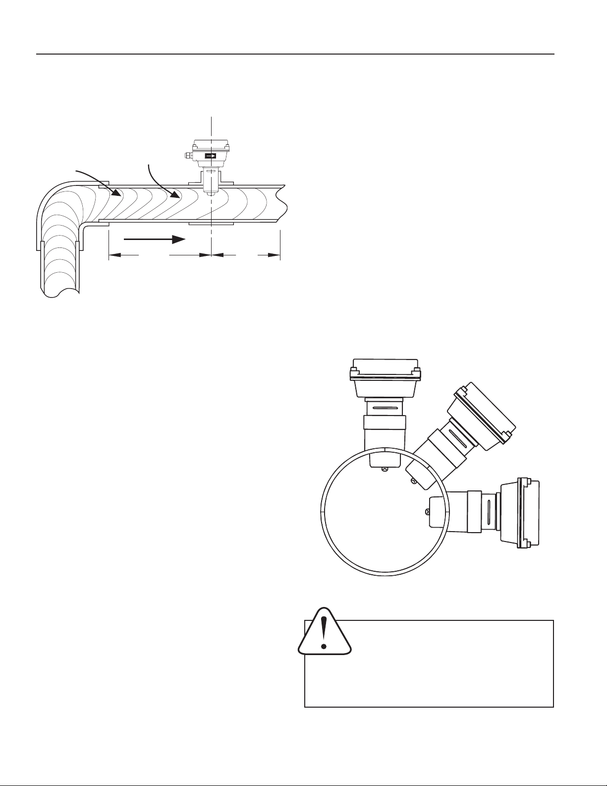
DISTORTED FLOWS
Distorted
Flow Profile
Faster Flow
Causes Meter
To Read High
FLOW
10X
Diameter Minimum
(See Below)
Okay position if there is
no air in the pipe
BEST POSITIONS
POSITIONING THE METER
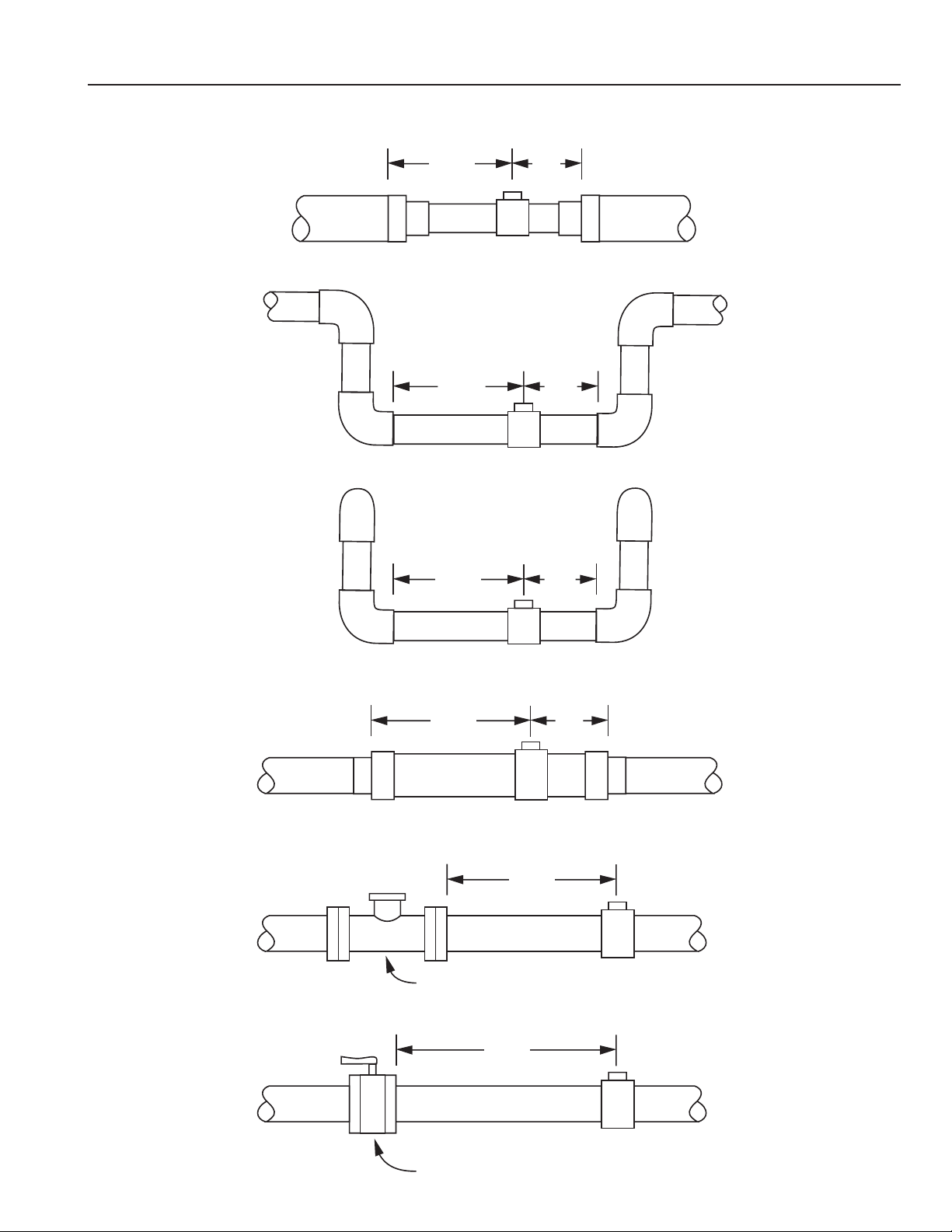
INSTALLATION
STRAIGHT PIPE RECOMMENDATIONS
(x = diameter)
5X
10X
5X10X
5X
20X
5X
20X
30X
50X
Reduced Pipe
Two Elbows In Plane
Two Elbows, Out Of Plane
Expanded Pipe
Spiral Flow
Swirling Flow
Propellor Meter
Partially Open Butterfly Valve Page 3
INSTALLATION
Caution: These flow sensors are not recommended for installation down-
stream of the boiler feedwater pump where installation fault may expose
the flow sensor to boiler pressure and temperature. Maximum recom-
mended temperature is 130°F (Plastic), 200°F (Metal).
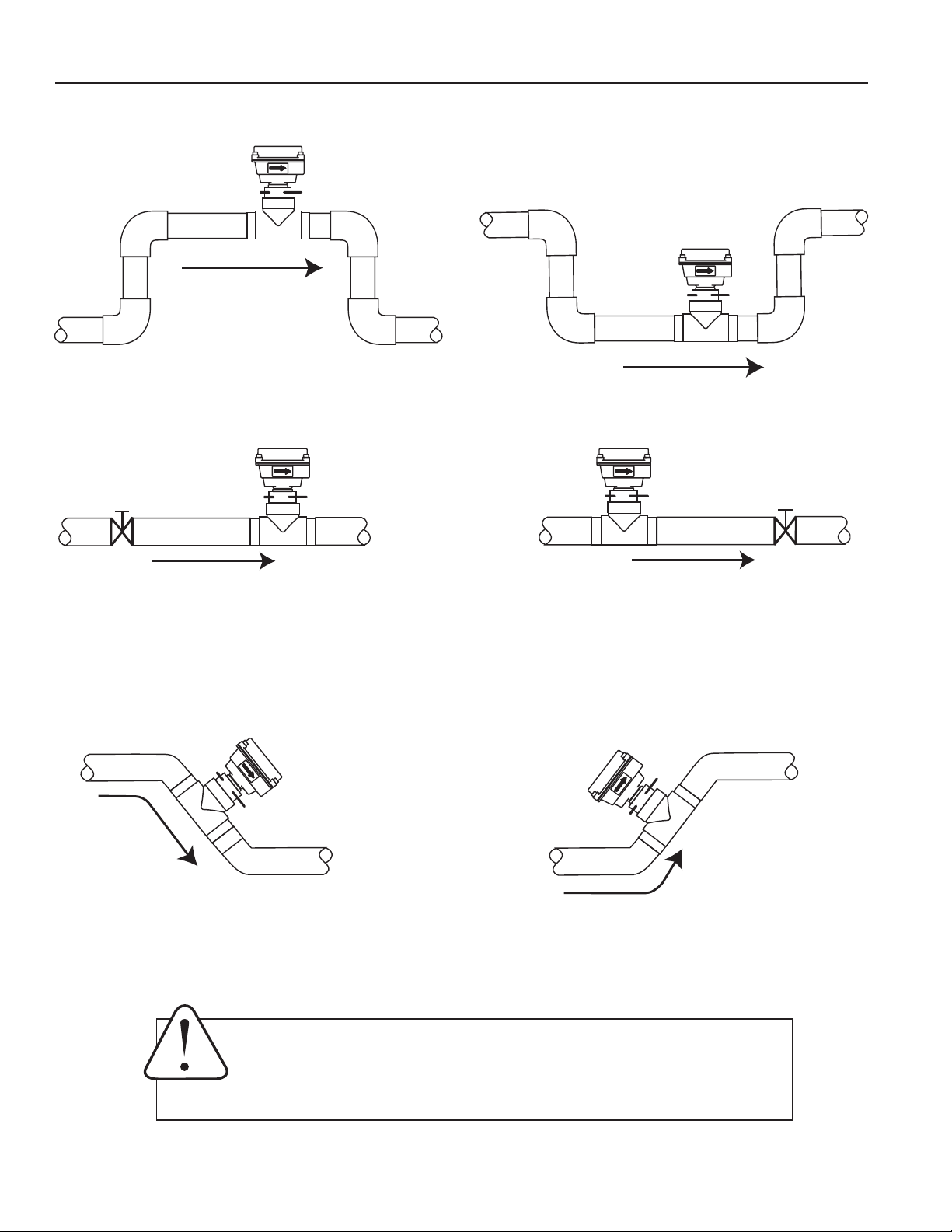
CORRECT AND INCORRECT INSTALLATIONS
CORRECT
INCORRECT
CORRECT
INCORRECT
Page 4
CORRECT
INCORRECT
Allows air pockets to form at sensor
Ensures full pipe
Post-valve cavitation can create air pocket Keeps pipe full at sensor
Air can be trapped Allows air to bleed off
Page 5
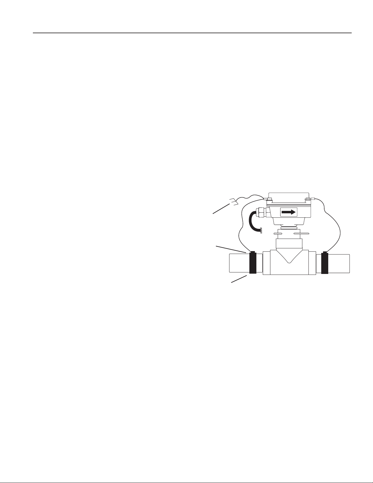
Grounding Guidelines:
• For best results, use a good quality earth ground,
such as metallic water piping, or a stake driven
into the ground.
• If the flow sensor is installed in metallic piping, for
optimum grounding clamp wires to the piping a
short distance to either side of the flow sensor
using hose-type clamps. Connect these wires to
the earth ground and to one of the housing screws.
General Electrical Guidelines:
• Whenever possible avoid running control cables
in the same conduit with AC power. Use shielded
control cable where this type of installation is
necessary.
• If using shielded cable, be sure that one end is
grounded
• Avoid routing flow sensor cables in close proximity
to a variable frequency drive.
• Recommended power and output wiring is 18-22
AWG control cable, shielded if the run length is
more than 18 feet (6 meters).
• Recommended voltage is 12-24 VDC. Note that
unregulated power supplies can vary from
nameplate voltage by a considerable amount.
When in doubt, use a regulated power supply.
See the Connections diagrams on the following pages, for
the appropriate terminals.
Power: A 12 - 24 Vdc power supply which is capable of
at least 250 mA current output is needed.
Pulse Output: This open-collector isolated output does
not supply power. It functions like a polarity-sensitive switch
closure. It reaches a maximum of 500 Hz at the maximum
flow rate of 20 feet/second. This pulse is generated in
both forward and reverse flow directions (see “Direction”
below).
Note:
This output is limited to 5 mA at 30 Vdc
maximum.
Direction Indicator: This output is switched by a solid
state relay, which is not polarity sensitive. It is “off” (open)
when flow is in the forward direction and “on” (closed)
when flow is in the reverse direction.
Note:
this output is
limited to 100 mA at 150 Vdc maximum.
ELECTRICAL CONNECTIONS
GROUNDING DIAGRAM
Ground To
Metallic Pipe
Earth
Ground
Hose Clamp
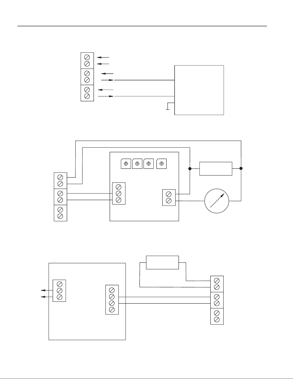
CONNECTIONS DIAGRAMS
Page 6
+
_
+
_
00
9
8
7
6
5
4
3
2
1
00
9
8
7
6
5
4
3
2
1
00
9
8
7
6
5
4
3
2
1
00
9
8
7
6
5
4
3
2
1
+
_
S+
_
+_
+_
+
+
_
_
+
_
+
+
_
_
COUNTER OR PLC
A055 4-20 mA OUTPUT
FT520 CONTROLLER
Power Input
Pulse Output
Direction Output
11 - 24 Vdc 250 mA max.
11 - 24 Vdc 5 mA max.
11 - 24 Vdc/Vac
100 mA max.
Frequency Input
25 hz per ft/sec
Direction Input
Com
Power Input
Pulse Output
Direction
EX SERIES
Unused
AO55
EX SERIES
Sensor
4-20 mA
4-20 mA
24 Vdc Power
Batching
Relay
Output
NC
COM
NO
+12V
SEN1
G
SEN2
EX SERIES
24 Vdc Power
Power
Input
Pulse
Output
Direction
FT520
COUNTER OR PLC
DIGITAL INPUT
Page 7
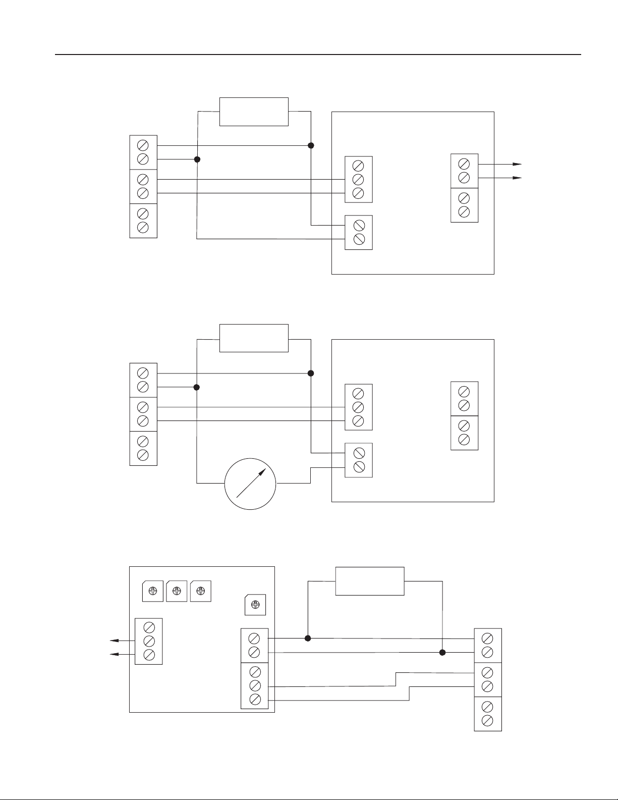
CONNECTIONS DIAGRAMS
+
_
S
+
_
+
_
+
_
+
+
_
_
+
_
+
_
+
_
S
+
_
+
_
+
+
_
_
+
_
+
_
00
9
8
7
6
5
4
3
2
1
00
9
8
7
6
5
4
3
2
1
00
9
8
7
6
5
4
3
2
1
00
9
8
7
6
5
4
3
2
1
+
_
S
+
_
+_
+
+
_
_
FT420 DISPLAY AND PROPORTIONAL FEED
Sensor
Input
Power Input
Pulse Output
Direction
Output
Power Input
Pulse Output
Direction
EX SERIES
Unused
EX SERIES
Sensor
4-20 mA
24 Vdc Power
24 Vdc Power
Power Input
Pulse Output
Direction
24 Vdc Power
Power
4-20mA
Pulse
Scaled
Pulse
Pass-Thru
To
Proportional
Feed
Metering
Pump
Sensor
Input
Power
4-20mA
Pulse
Scaled
Pulse
Pass-Thru
Unused
Power
Alarm
Relay
output
FT420 DISPLAY AND 4-20 mA OUTPUT
FS30 FLOW SWITCH
EX SERIES
FS30
FT420
FT420

OPERATION & MAINTENANCE
When the EX81 or 82 is powered up and there is no flow,
there should be no output pulses (or, if connected to the
FT420, flow rate should read “0”). If there are pulses...
Zero Adjustment. In some cases it may be necessary
to adjust the flow meter under no-flow conditions after it
has been installed.
To perform the adjustment, after determining that there is
no flow, short between the two pins marked “Zero Adj.”A
red LED light will come on for approximately 50 seconds
and then go out. The zero adjustment is completed.
Minimum Flow. As with any other flow sensor, there is a
rate below which the EX80-series sensor cannot read.
Check the flow rate table below for the minimum flow rate
detectable by the sensor for a given pipe size.
Filtering. The software of the EX80-series sensor filters
out electrical noise and also averages sudden variations
in the flow to smooth the output. It takes a matter of
seconds for the flow sensor to get up to full output when it
is powered up or when flow begins. If the unit responds
very slowly, it is probably due to excessive electrical noise.
If this is the case, check for adequate grounding to improve
the response.
Electrode Coating. Grease or other adhering, non-
conductive materials can stop flow detection if the
electrodes become heavily coated. To clean the electrodes,
remove the sensor from the pipe and gently scrub the
electrodes (three dark grey bumps) on the reading face of
the flow sensor. A mild soap (dishwashing liquid for
example) can be used to aid the cleaning process.
Page 8
K-factor. If the EX80 Series meter is ordered with its
fitting, it is factory calibrated in the fitting. A K-factor (meter
factor) is indicated on the side of the fitting. This repre-
sents the actual number of pulses per gallon the meter
produced during the factory flow test. This number can
entered into an FT420 or FT520 flow indicator to make it
read properly. If a pulse divider is being used, the K-factor
is the starting point for calculating the divider number.
LOCATION OF K-FACTOR
10031295
MF81T-P200
K: 53.6
Find Your K-Factor Here
1” 1-1/2" 2" 3" 4" 6" 8"
• Min .54 1.3 2 4.5 8 18 31
• Max 54 127 209 461 794 1800 3120
FLOW RANGE (GPM)

Problem Probable Cause Try...
No pulse output
Output pulses
incorrect
Check Plumbing
Connect to earth ground
Check for proper electrical wiring
Check for power across power
input terminals
Reverse connections
Change output connections
Select another flow meter
Check for proper ground
Check for proper electrical wiring
Select another flow meter
Check for full pipe or install meter in the
vertical position
Check for ten diameters upstream
AND
five diameters downstream
Pipe not full
Unit not grounded
Excessive electrical noise
No power
Power Reversed
Output connections reversed
Fluid conductivity <20 microseimans/cm
Missing or incorrect ground wire
Excessive electrical noise
Fluid conductivity <20 microseimans/cm
Empty pipe
Not enough straight pipe
TROUBLESHOOTING
Page 9

19026 72ND AVE SOUTH, KENT, WA 98032 USA
(P) 253.872.0284 (F) 253.872.0285
WWW.SEAMETRICS.COM 1.800.975.8153
LT-11792-B
03/09/04
Other manuals for EX80 Series
1
This manual suits for next models
5
Table of contents
Other Seametrics Accessories manuals

Seametrics
Seametrics PT2X User manual

Seametrics
Seametrics INW PT2X User manual

Seametrics
Seametrics CT2X User manual

Seametrics
Seametrics TX800 Series User manual

Seametrics
Seametrics INW CT2X User manual

Seametrics
Seametrics TempHion User manual

Seametrics
Seametrics Multi-Parameter Smart Sensor User manual

Seametrics
Seametrics PT2X-BV User manual

Seametrics
Seametrics INW LevelSCOUT User manual

Seametrics
Seametrics IP800 Series User manual


