Seametrics PT2X User manual

Precision Environmental Sensors
An ON
I
CON Brand
PROUDLY
MADE
IN THE
USA
C
e
r
t
i
f
i
e
d
C
o
m
p
a
n
y
ISO
9001:2008
PT2X
Pressure/Temperature Smart Sensor
and Data Logger Instructions
For PSIG
sensors, refer
to page 23
regarding
desiccant
use!

PT2X INSTRUCTIONS
Seametrics • 253.872.0284 Page 2 seametrics.com
General Information
General Information ........................................................................................................................................................................Page 3
Dimensions .........................................................................................................................................................................................Page 3
Specications .....................................................................................................................................................................................Page 4
How Pressure Sensors Work ........................................................................................................................................................Page 5
Initial Inspection and Handling...................................................................................................................................................Page 6
Do’s and Don’ts.................................................................................................................................................................................Page 6
Installation
Connecting External Power...........................................................................................................................................................Page 7
Connecting a PT2X to a Computer............................................................................................................................................Page 7
Connecting to Sensors ...................................................................................................................................................................Page 8
Cable Wiring ......................................................................................................................................................................................Page 9
Installing Aqua4Plus2.0..................................................................................................................................................................Page 9
Using the PT2X without Aqua4Plus 2.0 ...................................................................................................................................Page 9
Installing the Sensor........................................................................................................................................................................Page 10
Desiccant Use.....................................................................................................................................................................................Page 10
Grounding Issues..............................................................................................................................................................................Page 10
Settings and Calibration
Sensor Settings..................................................................................................................................................................................Page 11
Program Settings..............................................................................................................................................................................Page 11
Pressure Calibration.........................................................................................................................................................................Page 12
Depth to water ..................................................................................................................................................................................Page 13
Ground Elevation..............................................................................................................................................................................Page 14
Sta Gauge .........................................................................................................................................................................................Page 14
Removing calibration setup values............................................................................................................................................Page 14
Operation
Real-time Data...................................................................................................................................................................................Page 15
Data Logging......................................................................................................................................................................................Page 16
Reports .................................................................................................................................................................................................Page 18
A Word About Units........................................................................................................................................................................Page 18
Barometric Compensation............................................................................................................................................................Page 19
Direct Read Modbus/SDI-12
Setting Units for Direct Read .......................................................................................................................................................Page 20
Power Consideration.......................................................................................................................................................................Page 20
Reading via Modbus RTU..............................................................................................................................................................Page 20
Reading via SDI-12...........................................................................................................................................................................Page 21
Maintenance
Removing Debris from End Cone...............................................................................................................................................Page 23
Desiccant Tubes................................................................................................................................................................................Page 23
Sensor/Cable/End Connections..................................................................................................................................................Page 24
Changing Batteries...........................................................................................................................................................................Page 24
Troubleshooting
Problems/Probable Causes/Things to Try...............................................................................................................................Page 27
Warranty
Seametrics Limited Warranty.......................................................................................................................................................Page 28
TABLE OF CONTENTS
IF USING ALKALINE BATTERIES—PREVENT BATTERY LEAKAGE!
PT2X sensors are typically shipped with lithium batteries. If, however, you are
using alkaline batteries, be aware that under some circumstances alkaline
batteries can leak, causing damage to the sensor. To prevent leakage, the
following is recommended. (Does not apply to lithium batteries.)
• Change the batteries at least every 18 months.
• If the sensor will not be deployed for 3 months or more, remove the
batteries.

PT2X INSTRUCTIONS
Seametrics • 253.872.0284 Page 3 seametrics.com
GENERAL INFORMATION
The Seametrics PT2X Smart Sensor is an integrated data
logger and pressure/temperature sensor and is ideal for
monitoring groundwater, well, tank, and tidal levels, as well
as for pump and slug testing. This sensor networks with
all of the Seametrics Smart Sensor family. IThe PT2X is a
microprocessor based digital intelligent sensor designed
to measure and record pressure, temperature, and time,
using low power, battery operated circuitry.
Pressure is measured with an extremely rugged and stable
piezo-electric media-isolated pressure element combined
with a 16-bit analog-to-digital converter. This provides
extremely accurate and stable pressure input into the
microprocessor on the circuit board.
This industry standard digital RS485 interface device records
up to 520,000 records of pressure/level, temperature, and
time data, operates with low power, and features easy-to-
use software with powerful features. Constructed with 316
stainless steel or titanium, PTFE, and uoropolymer, this
sensor provides high-accuracy readings in rugged and
corrosive eld conditions.
Two internal 1.5V AA batteries power the PT2X. (Auxiliary
power supplies are available for data intensive applications.)
The unit is programmed using Seametrics’ easy-to-use
Aqua4plus 2.0 control software. Once programmed the
unit will measure and collect data on a variety of time
intervals.
Several PT2Xs, or a combination of PT2Xs and other
Seametrics Smart Sensors, can be networked together and
controlled directly from a single computer.
While most will use the PT2X with our free, easy-to-use
Aqua4Plus 2.0 software, it is by no means limited to that
software. You can use your own Modbus® RTU or SDI-12
software or logging equipment to read measurements,
thus tying into your existing systems and databases.
12.18” (30.9 cm)
8.37” (21.3 cm)
Diameter
0.75” (1.9 cm)
0.28” (0.7 cm)
0.28” (0.7 cm)
Cableless
0.25” (0.6
cm) Shorter
Battery Version
Non-Battery Version
Dimensions

PT2X INSTRUCTIONS
Seametrics • 253.872.0284 Page 4 seametrics.com
*Specications subject to change. Please consult out web site for the most current data (seametrics.com).
Modbus is a registered trademark of Schneider Electric.
1 Higher pressure ranges available upon request
2 ±0.25% accuracy FSO (max) at this range
3 Depth range for absolute sensors has 14.7 PSI subtracted to give actual depth allowed.
Housing & Cable Weight 0.8 lb. (0.4 kg)
Body Material Acetal & 316 stainless or titanium
Wire Seal
Material Fluoropolymer and PTFE
Cable Submersible: polyurethane, polyethylene, or ETFE (4 lb./100 ft., 1.8 kg/30 m)
Desiccant 1-3 mm indicating silica gel
Field Connector Standard
Temperature Operating Range Recommended: -15˚ to 55˚C (5˚ to 131˚F) Requires freeze protection kit if using pressure option in water
below freezing.
Storage Range Without batteries: -40˚ to 80˚C (-40˚ to 176˚F)
Power Internal Battery Two lithium ‘AA’ batteries - Expected battery life: 18 months at 15 min. polling interval (may vary do to
environmental factors)
Auxiliary 12 Vdc - Nominal, 6-16 Vdc - range
Communication Modbus® RS485 Modbus® RTU, output=32bit IEEE oating point
SDI-12 SDI-12 (ver. 1.3) - ASCII
Logging Memory 4MB - 520,000 records
Logging Types Variable, user-dened, proled
Logging Rates 8x/sec maximum, no minimum
Baud Rates 9600, 19200, 38400
Software Complimentary Aqua4Plus 2.0
Networking 32 available addresses per junction (Address range: 1 to 255)
File Formats .a4d and .csv
Output Channels Temperature Depth/Level¹
Element Digital IC on board Silicon strain gauge transducer, 316 stainless or Hastelloy
Accuracy ±0.5°C — 0° to 55°C (32˚ to 131˚F)
±2.0°C — below 0°C (32˚F) ±0.05% FSO (typical, static)
±0.1% FSO (maximum, static)
(B.F.S.L. 20˚C)
Resolution 0.1˚C 0.0034% FS (typical)
Units Celsius, Fahrenheit, Kelvin PSI, FtH₂O, inH₂O, mmH₂O, mH₂O, inH₂O, cmHg, mmHg, Bars, Bars,
kPa
Range -15˚ to 55˚C (5˚ to 131˚F) Gauge
Absolute³
PSI: 12, 5, 7, 15, 30, 50, 100, 300
FtH₂O: 2.32, 12, 35, 69, 115, 231, 692
mH₂O: 0.72, 3.5, 5, 10.5, 21, 35, 70, 210
PSI: 30, 50, 100, 300
FtH₂O: 35, 81, 196, 658
mH₂O: 10, 24, 59, 200
Compensated --- 0˚ to 40˚C (32˚ to 104˚F)
Max operating pressure 1.1 x full scale
Over pressure protection 3x full scale up to 300psi - for > 300psi (650 ft or 200 m) contact factory
Burst pressure 1000 psi (approx. 2000 ft or 600 m)
Environmental IP68, NEMA 6P
Specications*
GENERAL INFORMATION

PT2X INSTRUCTIONS
Seametrics • 253.872.0284 Page 5 seametrics.com
GENERAL INFORMATION
How Pressure Sensors Work
Liquids and gasses do not retain a xed shape. Both
have the ability to ow and are often referred to as
uids. One fundamental law for a uid is that the uid
exerts an equal pressure in all directions at a given level.
Further, this pressure increases with an increasing depth of
“submergence”. If the density of a uid remains constant
(noncompressible...a generally good assumption for water
at “normal” pressures and temperatures), this pressure
increases linearly with the depth of “submergence”.
We are all “submerged” in the atmosphere. As we increase
our elevation, the pressure exerted on our bodies decreases
as there is less of this uid above us. It should be noted
that atmospheric pressure at a given level does vary
with changes in the weather. One standard atmosphere
(pressure at sea level at 20º C) is dened to be 14.7 PSI
(pounds per square inch).
There are several methods to reference a pressure
measurement. Absolute pressure is measured with respect
to an ideal vacuum (no pressure). Gauge pressure is the
most common way we express pressure in every day life
and is the pressure exerted over and above atmospheric
pressure. With this in mind, gauge pressure (Pg) can be
expressed as the dierence between the absolute pressure
(Pa) and atmospheric pressure (Patm):
Pg = Pa - Patm.
To measure gauge pressure, atmospheric pressure is
subjected to one side of the system and the pressure to be
measured is subjected to the other. The result is that the
dierential (gauge pressure) is measured. A tire pressure
gauge is a common example of this type of device.
Recall that as the level of submergence increases (in a
noncompressible uid), the pressure increases linearly.
Also, recall that changes in weather cause the absolute
atmospheric pressure to change. In water, the absolute
pressure (Pa) at some level of depth (d) is given as follows:
Pa = Patm + kd
where k is simply a constant
(i.e.: 2.307 feet of water = 1 PSI)
Seametrics’ standard gauge submersible pressure
devices utilize a vent tube in the cable to allow the
device to reference atmospheric pressure. The resulting
gauge pressure measurement reects only the depth of
submergence. That is, the net pressure on the diaphragm
is due entirely to the depth of submergence.
Pressure Diagram: See Detail A.
Absolute pressure is given as Pa = Patm + kd
(where k is 2.307 feet of water)
d
Water Line
Patm
A
P = Patm + kd
“A”

PT2X INSTRUCTIONS
Seametrics • 253.872.0284 Page 6 seametrics.com
GENERAL INFORMATION
Initial Inspection and Handling
Upon receipt of your smart sensor, inspect the shipping package for damage. If any damage is apparent, note the signs
of damage on the appropriate shipping form. After opening the carton, look for concealed damage, such as a cut cable.
If concealed damage is found, immediately le a claim with the carrier.
Check the etched label on the sensor to be sure that the proper range and type were provided. Also check the label
attached to the cable at the connector end for the proper cable length.
Do’s and Don’ts
Don’t drop into well
Lower gently to prevent
damage
Don’t scrape cable
over edge of well
May nick or fray the
cable
Don’t bend cable sharply
May close o vent tube
and/or weaken internal
wires
Don’t support sensor
with the connector
Use a strain relief device
Do handle sensor with
care
Do store sensor in a
dry, inside area when
not in use
Do install sensor so the
connector end is kept
dry
Do install a desiccant
tube if using a gauge
sensor
PT2X INSTRUCTIONS
Seametrics • 253.872.0284 Page 7 seametrics.com
Connecting via RS232 Serial Port
Connect the weather-resistant connector to your
computer’s serial port as shown below.
Connecting sensor to your computer using
an RS485/RS232 adapter and an interface cable.
Connecting with a USB/Serial Adapter
USB-to-Serial cables are readily available from many
electronics and computer stores, as well as numerous sites
on the Internet. Seametrics has tested and recommends
the Keyspan USA-19HS. Install as follows:
• Plug into USB port.
• Install the drivers provided with the particular unit.
• Once drivers are installed connect to sensor
Connecting sensor to your computer using
a USB to Serial adapter and an interface cable.
PC or Laptop
Computer
RS485/RS232
Adapter
Interface Cable
Serial Port
Sensor
Screw-
Sensor
cap
Cableless
Conguration
Interface
Cable
PC or Laptop
Computer
USB PortUSB-to-Serial
Adapter
RS232/RS485
Adapter
Sensor
Screw-
Sensor
cap
Cableless
Conguration
INSTALLATION
Connecting External Power
The PT2X comes with two 1.5V AA internal batteries.
If auxiliary power is desired, you can use a 6–16 VDC supply
that can provide 15 mA. Connect to Vaux++ (pin 1 - white)
and Ground (pin 5 - blue) or contact Seametrics for auxiliary
power supplies.
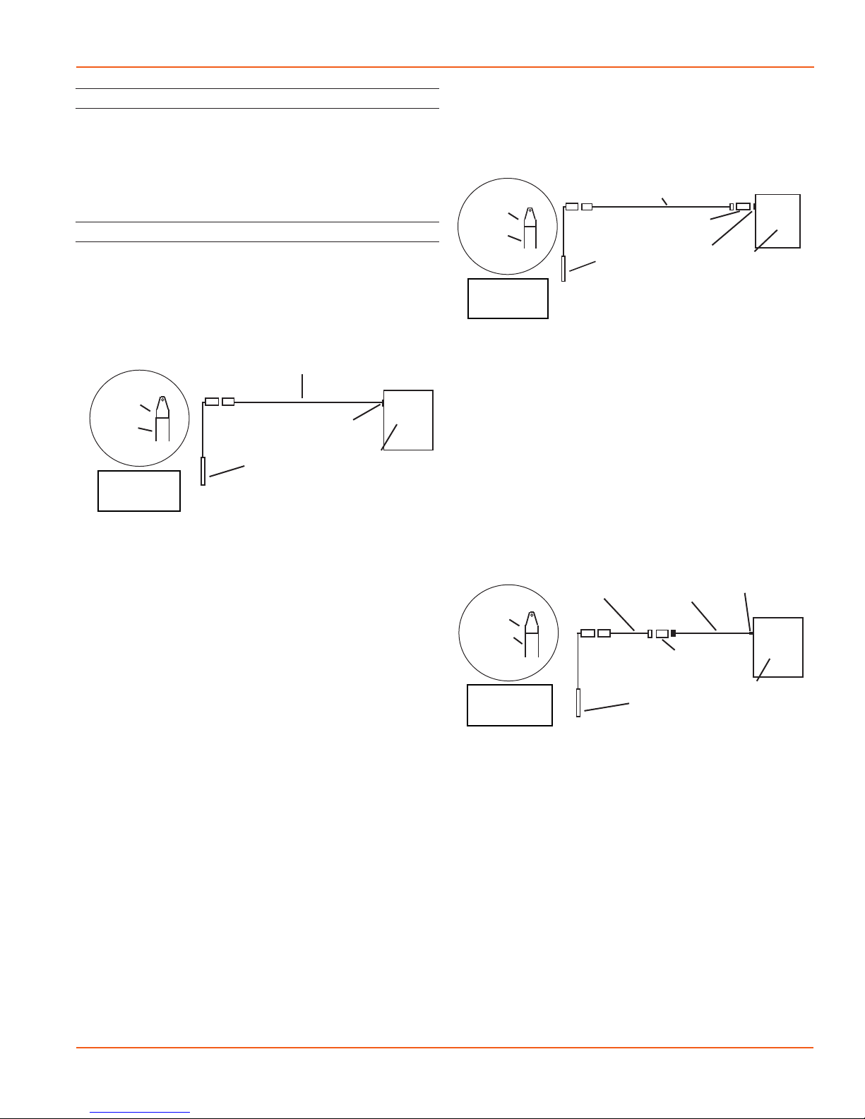
Connecting the PT2X to a Computer
Cabled sensors are terminated with a weather-resistant
connector. Cableless sensors are terminated with a weather-
resistant connector that is inside a screw-cap. Connect the
weather-resistant connector to your computer’s USB port
as shown below.
Connecting sensor to your computer using
Seametrics’ USB to RS485 adapter.
Aqua4Plus 2.0 communicates with the sensor using the
USB to RS485 adapter cable. This cable requires drivers to
be installed on your computer. If you are connected to the
Internet when you rst plug in the cable, it will normally
obtain and install the correct drivers automatically.
Alternate Connection Options
Seametrics recommends connecting the sensor to your
computer using the Seametrics USB cable. However, when
using Aqua4Plus 2.0, the sensor can also be connected
using an RS232 serial port or a USB-to-Serial cable, as
described below.
PC or Laptop
Computer
USB Port
USB to RS485
Adapter
Sensor
Cableless
Conguration
Screw-
Sensor
cap
PT2X INSTRUCTIONS
Seametrics • 253.872.0284 Page 8 seametrics.com
INSTALLATION
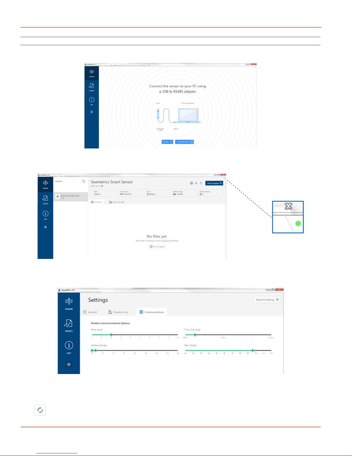
Connecting to Sensors
Aqua4Plus 2.0 is designed to automatically detect your communication cable and scan for sensors. It is recommended
you connect your USB/RS485 cable to your PC and have the sensor connected before opening Aqua4Plus 2.0.
If your cable and sensor were not connected before opening Aqua4Plus 2.0 simply connect and click Rescan. While
scanning is active you’ll see a green dot ash in the upper right corner of the program. Scanning is complete when this
dot stops ashing.
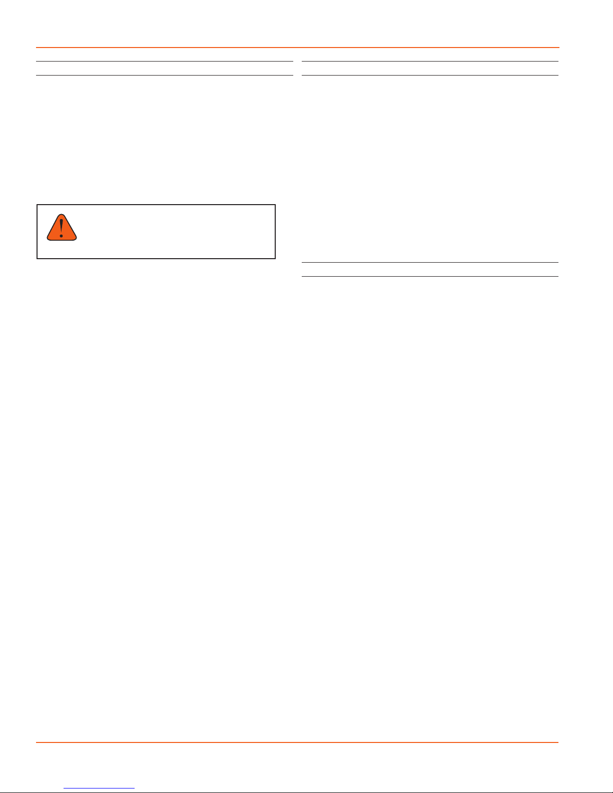
If your sensor still won’t connect you can expand the Modbus address range under program settings here:
Simply drag the Address Range slider higher up to increase the maximum Modbus address scanned. If you’ve scanned
all the way up through address 255 and still have no connection click Troubleshooting for further troubleshooting or
contact Seametrics Tech Support for assistance.
Click at any time to refresh sensor information.

PT2X INSTRUCTIONS
Seametrics • 253.872.0284 Page 9 seametrics.com
INSTALLATION
Cable Wiring
If you buy your cabled sensor with a connector installed
(the normal conguration), no further wiring is needed.
For reference purposes, the rst three diagrams below
show the pinout from the connector for various scenarios.
The nal diagram shows the pinout if you bought your
sensor without a connector for use with SDI-12.
For Modbus® with rmware lower than 2.0
— with 5-pin connector
For Modbus® with rmware 2.0 or higher
— with 5-pin connector
For SDI-12 with rmware 2.0 or higher
— with 5-pin connector
For SDI-12 with rmware 2.0 or higher
— without connector
White
Purple
Yellow
Brown
Blue
Shield
12 VDC+ (Vaux)
Modbus D- (Not used)
Modbus D+ (Not used)
SDI-12 Signal
12 VDC- (GND)
Earth ground
White
Purple
Yellow
Brown
Blue
Shield
12 VDC+ (Vaux)
Modbus D- (Not used)
Modbus D+ (Not used)
SDI-12 Signal
12 VDC- (GND)
1
2
3
4
5
5-Pin
Connector
White
Purple
Yellow
Brown
Blue
Shield
12 VDC+ (Vaux)
Modbus D-
Modbus D+
SDI-12 (Not used)
12 VDC- (GND)
1
2
3
4
5
5-Pin
Connector
White
Purple
Yellow
Brown
Blue
Shield
12 VDC+ (Vaux)
Modbus D-
Modbus D+
Digital I/O (Not used)
12 VDC- (GND)
1
2
3
4
5
5-Pin
Connector
Installing Aqua4Plus 2.0
The PT2X comes with the Aqua4Plus 2.0 host software
that is installed on your PC or laptop. Use this software to
program the datalogger, to retrieve data from the logger,
to view collected data, and to export data to external les
for use with spreadsheets or databases.
Refer to the software manuals for details on installing and
using Aqua4Plus 2.0.
Using the PT2X Without Aqua4Plus 2.0
Most users will use the PT2X with Seametrics’ Aqua4Plus
2.0 software. However, the PT2X is quite versatile,
communicating via either Modbus®or SDI-12 interfaces,
allowing you to do the following:
• Read a PT2X via Modbus®using your own software.
• Read a PT2X via SDI-12 protocol.
• Display readings from a PT2X on a panel meter.
If you want to use one of these methods, see page 20.
PT2X INSTRUCTIONS
Seametrics • 253.872.0284 Page 10 seametrics.com
INSTALLATION
Installing the Sensor
ThePT2X measurespressure. Themostcommon application
is measuring liquid levels in wells and tanks. In order to do
this, the sensor must be installed below the water level at a
xed depth. The installation depth depends on the range
of the sensor. One (1) PSI is equal to approximately 2.31
feet of water. If you have a 5 PSI sensor, the range is 11.55
feet of water and the sensor should not be installed at a
depth below 11.55 feet. If the sensor is installed below its
maximum range, damage may result to the sensor and the
output reading will not be correct.
Note: If you are using an absolute sensor and
you want to enter a depth-to-water reference
after data is collected, then see page 19 before
proceeding.
• Lower the sensor to the desired depth.
• Fasten the cable to the well head using a weather
proof strain-relief system. When securing a vented
cable, make sure not to pinch the cable too tightly
or the vent tube inside the cable jacket may be
sealed o.
• Take a measurement to insure the sensor is not
installed below its maximum range.
Be sure the supplied cap is securely placed on the weather-
resistant connector at the top of the cable. Do not install
such that the connector might become submerged with
changing weather conditions. The connector can withstand
incidental splashing but is not designed to be submerged.
For vented sensors, install the sensor so that the desiccant
tube will not ood or lie in water.
The sensor can be installed in any position; however, when
it leaves the factory it is tested in the vertical position.
Strapping the sensor body with tie wraps or tape will not
hurt it. Seametrics can provide an optional 1/4” NPT input
adapter which is interchangeable with the standard end
cone for those applications where it is necessary to directly
attach the sensor to a pipe, tank, or other pipe port. If the
sensor is being installed in a uid environment other than
water, be sure to check the compatibility of the uid with
the wetted parts of the sensor.
Desiccant Use
On vented sensors a desiccant tube prevents moisture in
the air from being sucked into the vent tube, which can
cause erratic readings and sensor damage.
The desiccant tube is lled with blue silica gel beads. A
locking barb and a hydrophobic water lter are attached to
the end of the desiccant tube. This lter prolongs the life of
the desiccant as much as three times over a desiccant tube
without the lter.
Install the sensor so that the desiccant tube and cable
connector will not ood or lie in water.
The desiccant is a bright blue color when active and dry. See
Maintenance section for care and changing of desiccant.
Grounding Issues
It is commonly known that when using electronic
equipment, both personnel and equipment need to be
protected from high power spikes that may be caused by
lightning, power line surges, or faulty equipment. Without
a proper grounding system, a power spike will nd the path
of least resistance to earth ground—whether that path is
through sensitive electronic equipment or the person
operating the equipment. In order to ensure safety and
prevent equipment damage, a grounding system must be
used to provide a low resistance path to ground.
When using several pieces of interconnected equipment,
each of which may have its own ground, problems with
noise, signal interference, and erroneous readings may be
noted. This is caused by a condition known as a Ground
Loop. Because of natural resistance in the earth between
the grounding points, current can ow between the points,
creating an unexpected voltage dierence and resulting
erroneous readings.
The single most important step in minimizing a ground loop
is to tie all equipment (sensors, dataloggers, external power
sources, and any other associated equipment) to a single
common grounding point. Seametrics recommends
connecting the shield to ground at the connector end.

PT2X INSTRUCTIONS
Seametrics • 253.872.0284 Page 11 seametrics.com
Sensor Settings
Once connected you’ll see the Sensor screen appear and
display the connected sensor(s) details. Mousing over---
icons will provide tool-tips, mouse over to view sensor
rmware and serial number details.
To change general sensor settings click in the sensor
screen. This allows you to change the following:
Click to rename the sensor
To change Modbus address and/or Baud Rate simply select
the desired address and/or Baud Rate from the drop down
menus. Sensor will automatically reconnect at new address
and/or Baud Rate
To change the Direct Read output units (for direct Modbus
or SDI12 integration) simply select the desired output
units from the drop down menus. To change Aqua4plus
2.0 display units scaling see Program Settings.
Sensor Clock can be synced with your PC time or set
manually if desired. To set manually enter your desired
date/time and click Set Time.
When batteries are changed out make sure to reset the
battery information here, simply check the I have just put
in new batteries box and select the battery type that was
installed from the drop down menu.
SETTINGS AND CALIBRATION
Program Settings
To view/change Aqua4Plus 2.0 settings click in the blue
side-bar menu
Under the General Settings tab you can change the default
data folder location. This is where your Reports are saved
to on your PC.
The Zoom Factor slider can be used to adjust the font size
within Aqua4plus 2.0.
Uncheck the Allow app to collect anonymous usage
statistics box if you would like to opt out. This information
is used to track Aqua4plus 2.0 reliability across dierent
system congurations.
Under the Display Units tab you can select your desired
display units for the supported channels. These may be
changed at any time and associated Real-Time readings and
Reports will rescale to the currently selected display unit. To
change Direct Read units scaling see Sensor Settings.
PT2X INSTRUCTIONS
Seametrics • 253.872.0284 Page 12 seametrics.com
Under the Communications tab you can change your
Modbus communication settings. Typically you will only
need to change the address range to connect to sensors
outside of Modbus address 1-10. In certain cases we
may need to change the Retry and Timeout settings to
overcome communication issues on very long, or corroded
cabling. See Troubleshooting section or contact Seametrics
Tech Support for details.
To restore factory default settings click
SETTINGS AND CALIBRATION
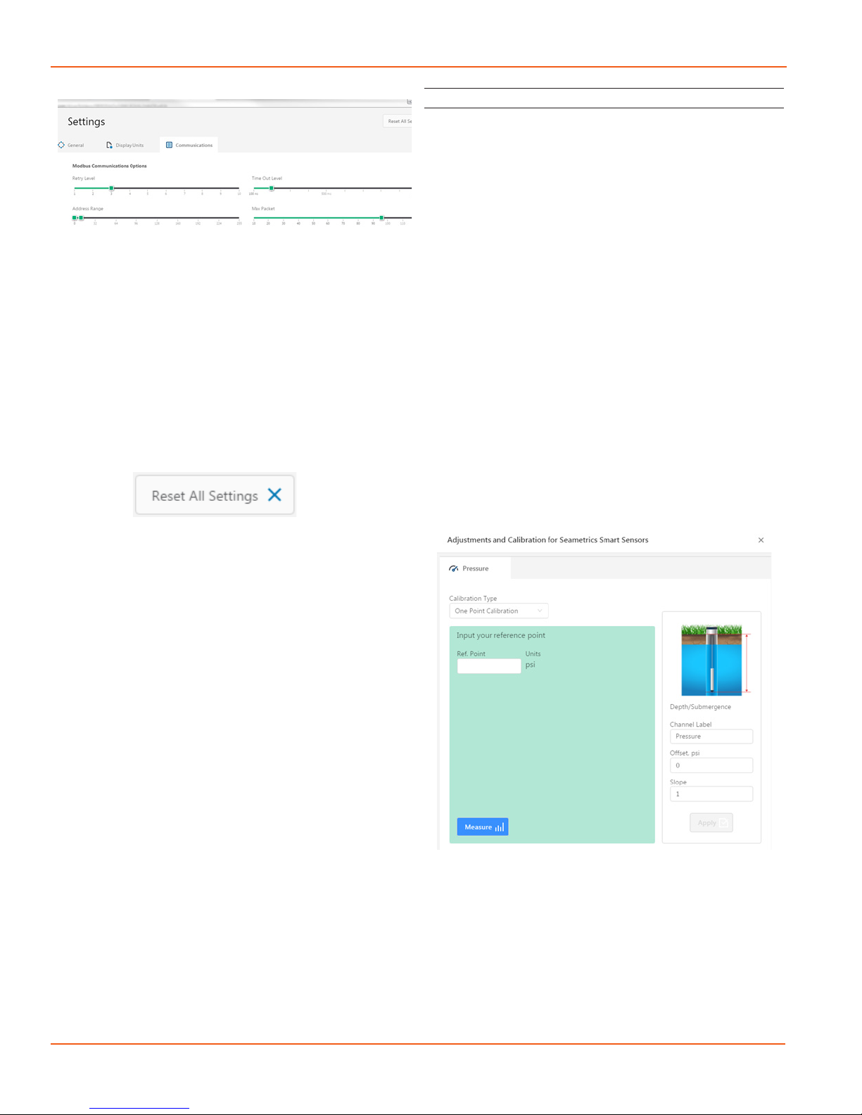
Pressure Calibration
To perform a calibration setup on the pressure channel
rst connect to the sensor and ensure all data has been
uploaded and erased from the sensor. Next select the
calibration button (example images can be found under
conductivity calibration page 12).
Next select the calibration setup you’d like to perform:
Comrm desired measurement units and click Continue.
Submergence:
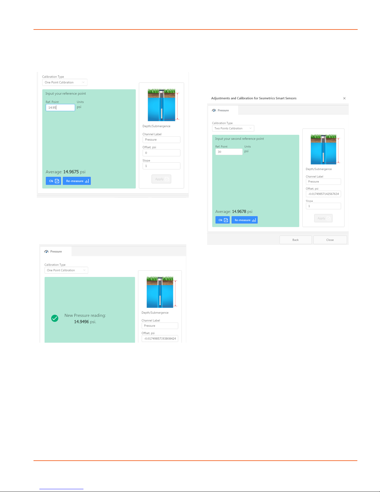
One Point/Zero Point Calibration:
To zero pressure output to atmospheric pressure position
the sensor in air in its desired installation position (typically
vertical, if sensor will be installed horizontally position as
such during 0 point calibration). Select 1 point Calibration
under Calibration Type.
For PSIG sensors use 0 as the reference value and click
Measure.
For PSIA sensors enter current barometric pressure from
a known accurate barometer set to matching units. Enter
your reference value in the Ref. Point box and click Measure.
PT2X INSTRUCTIONS
Seametrics • 253.872.0284 Page 13 seametrics.com
SETTINGS AND CALIBRATION
Aqua4Plus 2.0 will take 10 readings and display the average.
Watch for stability while Aqua4Plus 2.0 is measuring to
ensure an accurate calibration.
Click Ok to accept the reading and Aqua4Plus 2.0 will
calculate a new pressure oset. Click Apply to conrm the
new oset value and Aqua4Plus 2.0 will provide a real time
reading to verify calibration was successful:
2 Point submergence calibration ONLY RECOMMENDED
IF YOU HAVE AN ACCURATE PRESSURE REFERENCE.
Our Smart Sensors rarely change slope during normal
use, however if you have an accurate pressure source it is
possible to perform a 2 point calibration on the pressure
channel.
Select 2 point Calibration under Calibration Type
Perform rst point calibration as listed above and click Next
Enter known pressure value in matching units in the Ref.
Point box for second point measurement
Aqua4Plus 2.0 will take 10 measurements and display
the average. Watch for stability while Aqua4Plus 2.0 is
measuring to ensure an accurate calibration.
Click Ok and Aqua4Plus 2.0 will calculate the new slope
and oset values. Click Apply to conrm the new slope and
oset values and Aqua4Plus 2.0 will provide a real time
reading to verify calibration was successful.
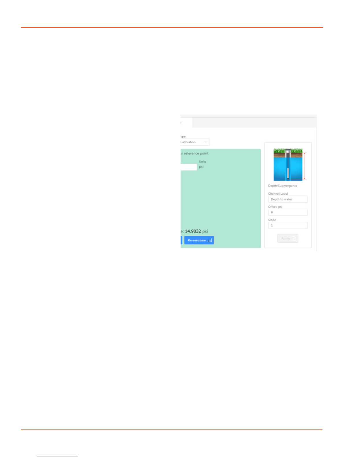
Depth to water (for PSIG sensors only, see Barometric
Compensation Utility for PSIA sensors)
Position the sensor in its desired location and ensure all
data has been uploaded and erased from the sensor before
proceeding with calibration.
Once positioned connect to sensor and select the
calibration button, followed by selecting the Depth to
Water option. Double check measurement units selection
before proceeding.
Enter your current depth to water (Typically obtained from
a water level indicator) value in the Ref. Point box, making
sure to match measurement units.
PT2X INSTRUCTIONS
Seametrics • 253.872.0284 Page 14 seametrics.com
SETTINGS AND CALIBRATION
Click Measure and Aqua4Plus 2.0 will take 10 readings and
display the average. Watch for stability while Aqua4Plus 2.0
is measuring to ensure an accurate calibration.
Click Accept and Aqua4Plus 2.0 will calculate a new slope
and oset, click Apply to accept the new slope and oset
and Aqua4Plus 2.0 will provide a real time reading to verify
calibration was successful.
Groundwater Elevation
Position the sensor in its desired location and ensure all
data has been uploaded and erased from the sensor before
proceeding with calibration.
Once positioned connect to sensor and select the calibration
button, followed by selecting the Groundwater Elevation
option. Double check measurement units selection before
proceeding.
Enter your current Groundwater Elevation reading in the
Ref. Point box, making sure to match measurement units.
Click Measure and Aqua4Plus 2.0 will take 10 readings and
display the average. Watch for stability while Aqua4Plus 2.0
is measuring to ensure an accurate calibration.
Click Accept and Aqua4Plus 2.0 will calculate a new oset,
click Apply to accept the new oset and Aqua4Plus 2.0
will provide a real time reading to verify calibration was
successful.
Sta Gauge
Position the sensor in its desired location and ensure all
data has been uploaded and erased from the sensor before
proceeding with calibration.
Once positioned connect to sensor and select the
calibration button, followed by selecting the Sta Gauge
option. Double check measurement units selection before
proceeding.
Enter your current Sta Gauge reading in the Ref. Point
box, making sure to match measurement units.
Click Measure and Aqua4Plus 2.0 will take 10 readings and
display the average. Watch for stability while Aqua4Plus 2.0
is measuring to ensure an accurate calibration.
Click Accept and Aqua4Plus 2.0 will calculate a new oset,
click Apply to accept the new oset and Aqua4Plus 2.0
will provide a real time reading to verify calibration was
successful.
Removing calibration setup values
To return to factory default simply enter an oset of 0 and
slope of 1 in the Oset and Slope boxes:
Click Apply to conrm settings and Aqua4Plus 2.0 will
provide a real time reading to conrm.
Adjusting for specic gravity
You man enter the specic gravity of your uid in the Slope
eld to adjust for specic gravity when needed. Click Apply
to conrm settings and Aqua4Plus 2.0 will provide a real
time reading to conrm.

PT2X INSTRUCTIONS
Seametrics • 253.872.0284 Page 15 seametrics.com
OPERATION
Real-time readings default to a 1 second interval for 1
minute, to adjust enter your desired settings here:
Note: Currently this data is not saved and is for viewing
current conditions only. To save the data to sensor memory
see Data Logging section. You can run Real-time Data
while logging is active.
Real-time Data
Connect to sensor and select the Real-time data tab
To start real-time readings click Start, readings default to
table view
To switch to Real-time graphing view click the graph
icon
PT2X INSTRUCTIONS
Seametrics • 253.872.0284 Page 16 seametrics.com
OPERATION
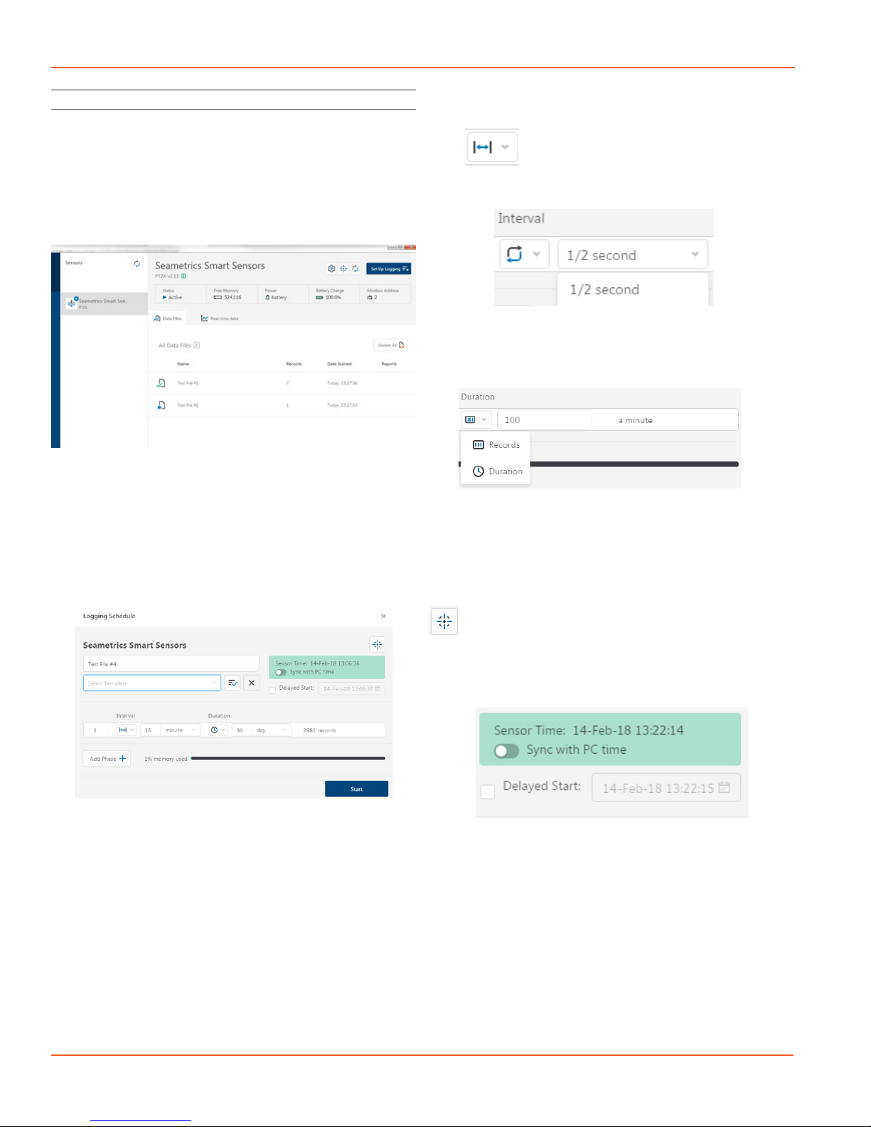
Data Logging
Select Set Up Logging from the sensor screen
If there are no les currently on the sensor you’ll see the
Set Up Logging button active under the Data Files tab as
well as in the upper menu. Once les have been started/
logged on the sensor they will be displayed under the Data
Files tab.
Setting Up Logging Window
Here you will name your data le and set up the recording
interval and duration of each logging phase. Select your
desired recording interval and duration for each phase,
Aqua4Plus will display the available memory at the bottom
of the window.
Click to switch between interval and continuous
data recording (PT2X & CT2X only) Select your continuous
rate from the drop down box here.
Duration can be set by either number of records
Or by setting a duration time
When set by number of records the time of the recording
phase will be displayed detailing how long that phase will
run. When set by time, the total number of records for that
phase will be displayed.
If you need to check settings or perform a calibration click
before proceeding with logging setup to switch to the
Settings and Calibration screen.
You may sync the sensor clock with the PC clock when
starting logging by clicking the slider here.
Check the Delayed Start box and enter the desired date/
time you would like logging to start. This is useful for
syncing data when setting up multiple sensors on a site.
Data will start logging at the set date/time rather than
immediately when Start is pressed.
PT2X INSTRUCTIONS
Seametrics • 253.872.0284 Page 17 seametrics.com
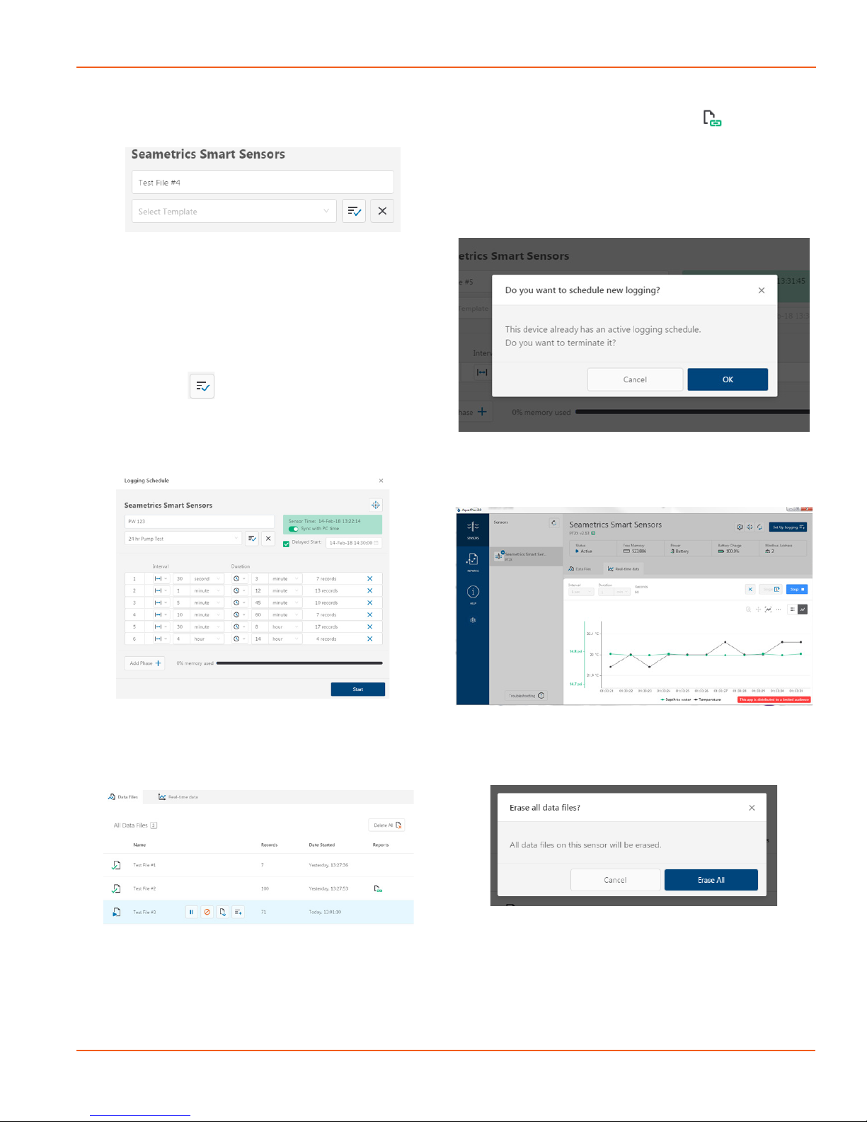
Data le name defaults to Test File # and may be re-named
here.
The 3 previous Logging Schedules that were programmed
to a sensor will be listed under the Select Template drop
down menu. There you will also nd pre-programmed
logging schedules such as 24 hour pump test, along with
any custom logging schedules saved by the user.
To save a logging schedule as a template enter desired
settings and click This will add your custom schedule
to the Select Template menu.
Once all the desired settings are made simply click Start to
begin logging.
This will return you to the Sensor screen and your status
will change to Active with the data le displayed under the
Data Files tab. Mouse over an active le to pause, terminate,
download, or view logging setup details.
Data les already downloaded will show in the Reports
column, clicking here will bring you to the reports screen to
view the data. See Reports section for details.
You may only have 1 active data le recording on each
sensor, however you can store multiple les in memory if
desired.
Starting a new le will automatically terminate the active
logging and begin the new logging schedule. Real-time
data is available during active logging.
To delete les from memory make sure they have all been
downloaded to Reports. Files are removed from memory
all at once rather than individually.
Once conrmed les are permanently deleted from the
sensor memory.
OPERATION
PT2X INSTRUCTIONS
Seametrics • 253.872.0284 Page 18 seametrics.com
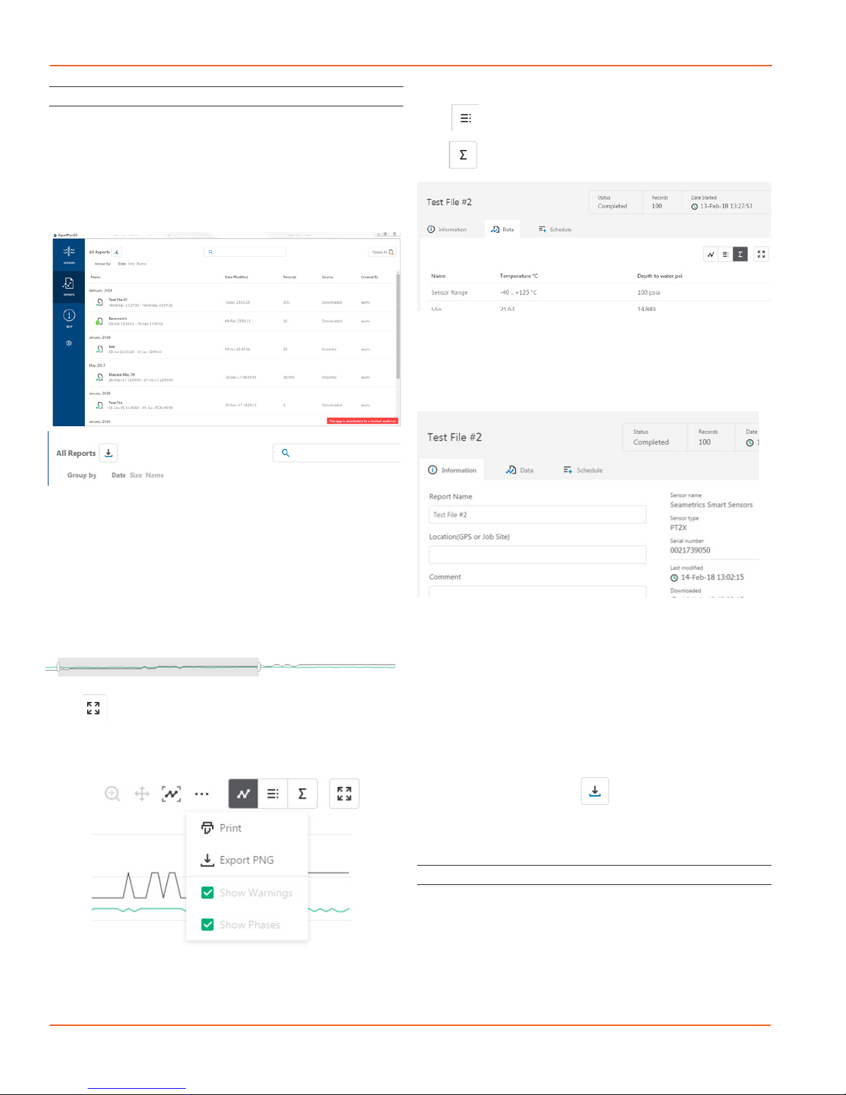
Reports
Data downloaded from your sensor is stored in the Reports
section of Aqua4Plus 2.0 for viewing and editing. The les
will be saved to default data folder on your PC as well. See
Program Settings for default data folder location.
In the main view you’ll see a list of reports sorted by date,
size, or le name as selected here
You can also search reports by keyword using the search
box
Click on a report to bring up the report details
Reports are displayed in graphing view by default. You can
zoom to specic sections by selecting a section with you
mouse or by adjusting the slider below the graph, shown
below.
Click to switch to full screen graphing view
Graph saving and export options are available here
Click to view data as a table
Click to view data statistics
The Information tab is a new feature allowing users to add
metadata to their reports such as site location, eld notes,
or comments.
The Schedule tab will display the logging setup details for
the report
Click Export to export the report as a .csv le or .a4d le for
distribution or use in 3rd party software.
Click Delete to delete the report from Aqua4Plus 2.0
You can also import .a4d les from compatible sensors into
Aqua4Plus 2.0 by clicking at the top of the Reports
screen.
A Word About Units
Readings from the PT2X Smart Sensor can be displayed in
various units, such as PSI, Ft. H2O, or mm H2O for pressure,
or degrees Celsius or degrees Fahrenheit for temperature.
Select the units you want from the Options | Display Units
menu or from the Congure Menu | Program Conguration
| Set Computer Display Units.
OPERATION

PT2X INSTRUCTIONS
Seametrics • 253.872.0284 Page 19 seametrics.com
OPERATION
Barometric Compensation
For PSIA sensors we’ve built a new barometric compensation
utility into the Reports section. Click on a report to
compensate the data for barometric pressure.
Corresponding barometric les are ltered by date/time
and displayed to the left. Select the barometric le you
would like to use to compensate the report, select either the
Submergence or Depth To Water tab, then click Continue.
If compensating for Depth to Water enter your depth
to water reference measurement and the date/time the
measurement was taken (typically taken with a water level
indicator before data is uploaded from the sensor) before
clicking Continue.
Aqua4Plus 2.0 will perform the barometric compensation
and create a new compensated report. Original reports are
retained as uploaded.
Compensated report can then be viewed and exported as
needed.

PT2X INSTRUCTIONS
Seametrics • 253.872.0284 Page 20 seametrics.com
DIRECT READ MODBUS/SDI-12
Direct Read (Modbus®or SDI-12)
While the PT2X comes with Seametrics’ easy to use
Aqua4Plus 2.0, you can also use standard Modbus® RTU
or SDI-12 equipment to easily take readings, so as to tie
into your existing equipment or networks.
You may need to use Aqua4Plus 2.0 to make a few settings
prior to directly reading the PT2X with your equipment.
These might include the units for the returned values
and/or the Modbus baud rate. These are described in the
following sections.
For Modbus direct read, you must have PT2X rmware 1.5
or higher. For SDI-12, you must have rmware 2.0 or higher.
Setting Units for Direct Read
By default, the PT2X uses the following units:
Temperature Degrees Celsius
Pressure PSI
If you want to change to dierent units, for example,
degrees Fahrenheit for temperature or feet of water for
pressure, set these units using Aqua4Plus 2.0. See sensor
settings.
Power Consideration
If your sensor does not have internal batteries and is not
powered continuously by an auxiliary power supply, then
you must turn power on to the sensor at least two seconds
before a reading is to be taken to allow the sensor to warm
up.
Reading Via Modbus®RTU
Setting Baud Rate
Your PT2X comes congured to communicate at 38,400
baud, with 8 data bits, one stop bit, and no parity. The
sensor can also be set to 19,200 or 9600 baud, if needed
for your application. You must use Aqua4Plus 2.0
If needed, set your PT2X to the desired baud rate as follows:
• Click on the Congure menu, and then select
Advanced.
• From the yout menu, select Sensor Baud Rate. (You
may be asked for a password. Enter admin.)
• On the popup box, click the down-arrow, select the
baud rate you need, and then click OK.
Once you have changed the baud rate on the PT2X, you
will not be able to talk to it with Aqua4plus 2.0 until you
change the baud rate for Aqua4Plus 2.0, as follows:
• Click the Options menu, and then select Baud Rate.
• On the popup box, click the down-arrow, select the
baud rate you need, and then click OK.
The current Aqua4plus 2.0 baud rate is displayed in the
lower right corner of the main Aqua4plus 2.0 window.
Taking Measurements
Reading Registers
Read measurements using Modbus function 03 – Read
Holding Registers. Readings are located in two registers
each, starting at address 62592. (PT2X register addressing
is zero based, i.e., starts at zero. If your equipment uses one
based addressing, you will need to add one to the register
addresses.)
Measurement Timing
When you request a reading via Modbus, the sensor wakes
up, returns the current values in the registers, and then
starts taking new readings and updating the registers.
After approximately 10 seconds, if no more readings have
been requested, the sensor goes back to sleep.
Because of this, the rst reading you get will be old. If you
are taking readings at intervals of less than 10 seconds,
simply ignore the rst reading — all remaining readings will
be current. On the other hand, if you are taking readings
at intervals of greater than 10 seconds, take a reading,
ignore it, wait one second, take another reading. Record
this second reading.
Data Format
The data is returned as 32-bit IEEE oating-point values,
highword rst, also referred to as big-endian or oat
inverse.
For further information and detailed Modbus examples,
see Seametrics’ Technical Bulletin, available on www.
seametrics.com.
Addresses for PT2Xs with rmware lower than 2.0
Zero based One based
Pressure 62592 62593
Temperature 62594 62595
Addresses for PT2Xs with rmware 2.0 or higher
Zero based One based
Temperature 62592 62593
Pressure 62594 62595
Table of contents
Other Seametrics Accessories manuals

Seametrics
Seametrics TX81 Series User manual

Seametrics
Seametrics IP800 Series User manual

Seametrics
Seametrics INW LevelSCOUT User manual

Seametrics
Seametrics INW CT2X User manual

Seametrics
Seametrics INW PT2X User manual

Seametrics
Seametrics EX80 Series User manual

Seametrics
Seametrics CT2X User manual

Seametrics
Seametrics TempHion User manual

Seametrics
Seametrics TX800 Series User manual

Seametrics
Seametrics DO2 User manual


