KTY0010001SE 036570 010321
6
hygge radio RELAY RECEIVER CONNECTION DIAGRAMS
The only electrical connections to be made are those related to the relay receiver hygge radio.
The relay receiver can be powered at 230V 50Hz or at 24V . The Land Nterminals power the receiver at 230V and are to
be connected to the mains voltage with the neutral on the terminal N. Alternatively connect the power to the terminals aand Nto
power the receiver at 24V .
Terminals 1, 2 and 3 are the contacts, voltage free, type SPDT of the channel 1 output relay. Terminals 4, 5 and 6 are the contacts,
voltage free, type SPDT of the channel 2 output relay.
Figure 1 and 2 illustrate how to connect the receiver to a boiler. The boiler will be turned on when the programmable thermostat
associated with output 1 asks for heat (heating mode). Figure 3 and 4 illustrate how to connect a valve that will be powered when
the output is activated and this is when the programmable thermostat asks for heat (heating mode) using the NA contact of the relay.
It is possible to connect, to the two relay outputs, two different hygge, every hygge controls the related valve, this way it is possible
to manage two areas, e.g.: living floor and bedrooms. Sometimes it may be required to pilot one boiler by two different hygge (e.g.:
two areas, living floor and bedrooms): in this case it is possible to connect the two outputs of the receiver in parallel, so the boiler is
turned on, when at least one of the two hygge asks for heat. Refer to the diagram of Fig. 1 or 2 and add a connection between the
terminals 1 and 4 and a connection between terminals 3 and 6.
The outputs, terminals from 1 to 6, are voltage free and isolated with double insulation compared to the rest of the receiver. It is
therefore possible to power the receiver at low voltage SELV (24V ) and simultaneously control a high voltage load (230V ), as
on Fig. 2 or 4. In this case it is necessary to maintain a separation between the cables SELV 24V and 230V in compliance with
current regulations. In particular it is necessary to x the cable assemblies with cable ties separating the SELV wires from the others
in order to avoid the case where, even if a cable is accidentally disconnected, this can’t reduce the isolation towards SELV.
WARNING
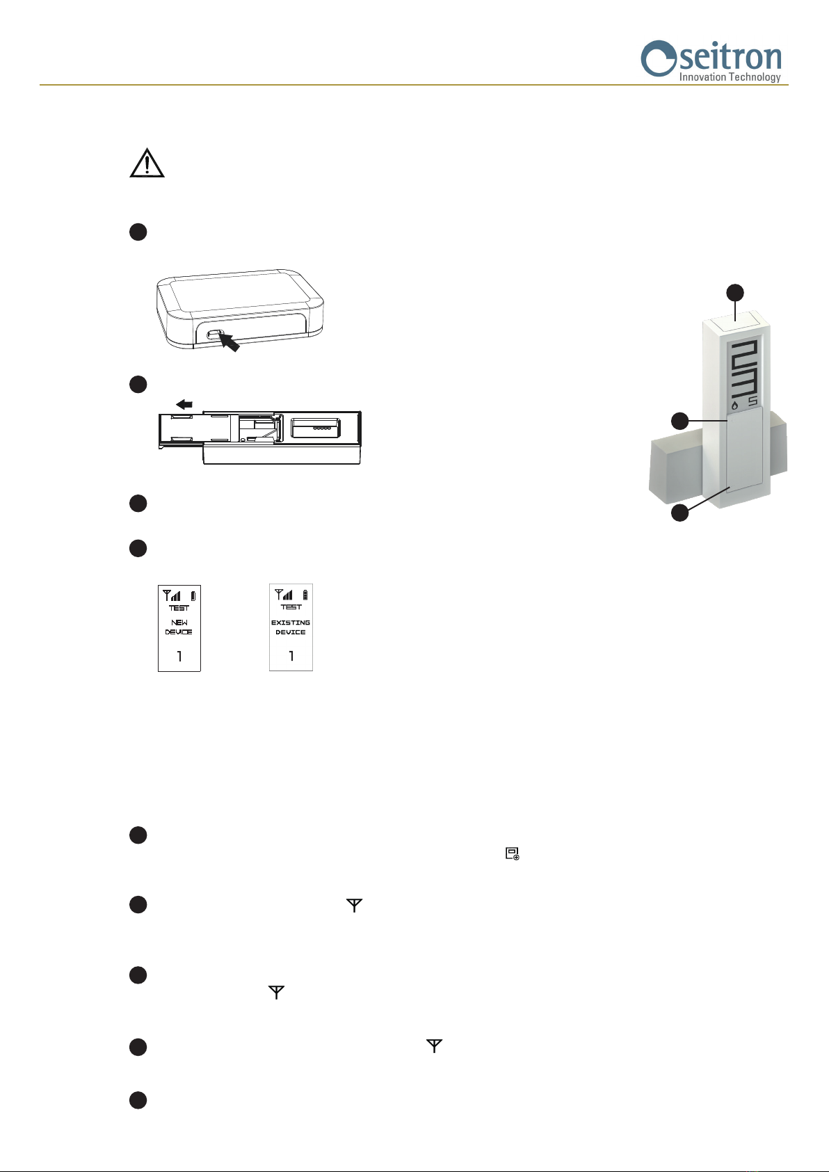
- Before proceeding with the installation of the hygge radio relay receiver make sure that the radio signals transmitted by the hygge
programmable thermostats are correctly received by the relay receiver.
- If the load driven by the hygge radio relay receiver works with mains voltage, the connections must be made via an omnipolar switch
complying with current standards and with contact opening of at least 3 mm in each pole.
- The power supply at 24Vshall be provided with overload protection.
- Installationandelectricalwiringsofthisappliancemustbemadebyqualiedtechniciansandincompliancewiththecurrentstandards.
- Before wiring the appliance be sure to turn the mains power off.
Make the electrical connections following the appropriate diagram.
To the boiler
To the boiler
RELAY 1
Fig. 1 Fig. 3
Fig. 2 Fig. 4
RELAY 2
RELAY 1 RELAY 2
RELAY 1 RELAY 2
RELAY 1 RELAY 2