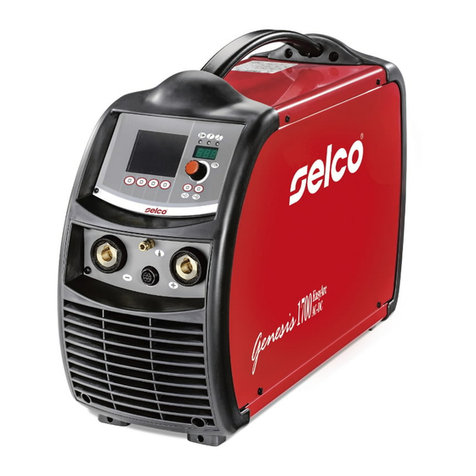
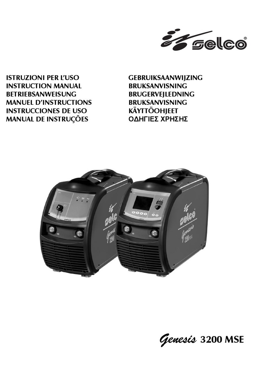
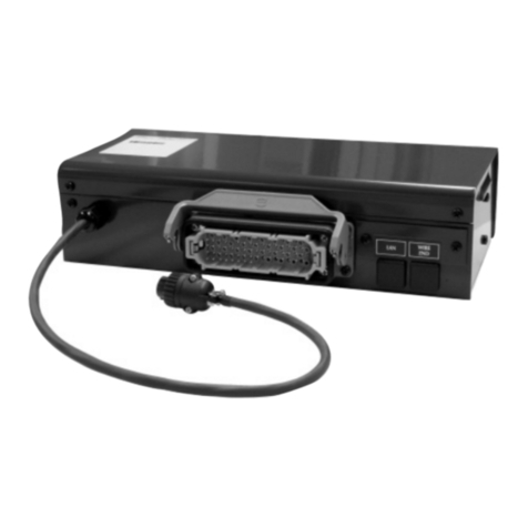
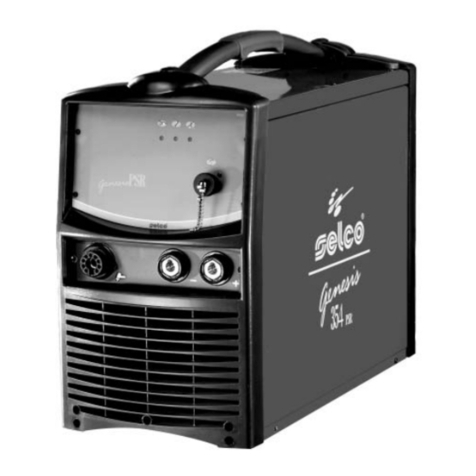
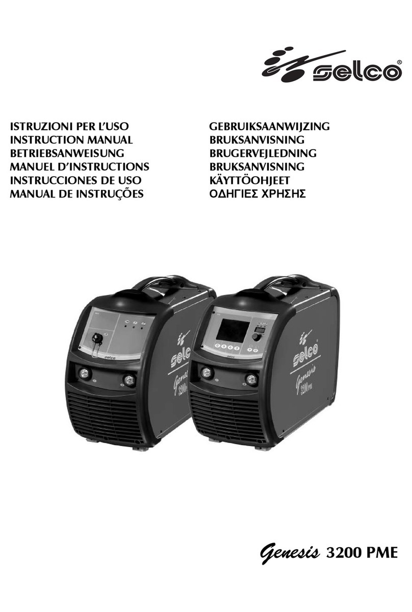
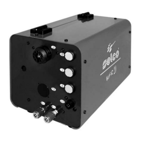
Sel Genesis 282-352-503 PME User manual

Genesis
282-352-503 PME
ISTRUZIONI PER L’USO
INSTRUCTION MANUAL
BETRIEBSANWEISUNG
MANUEL D’INSTRUCTIONS
INSTRUCCIONES DE USO
MANUAL DE INSTRUÇÕES
GEBRUIKSAANWIJZING
BRUKSANVISNING
BRUGERVEJLEDNING
BRUKSANVISNING
KÄYTTÖOHJEET

Cod. 91.08.0561
Data 21/06/07
Rev. E
ITALIANO . . . . . . . . . . . . . . . . . . . . . . . . . . . . . . . . . . . . . . . . . . . . . . . . . . . . . . . . . . . . . . . . . . . . . . . . . . . . . . . . . .3
ENGLISH . . . . . . . . . . . . . . . . . . . . . . . . . . . . . . . . . . . . . . . . . . . . . . . . . . . . . . . . . . . . . . . . . . . . . . . . . . . . . . . . .13
DEUTSCH . . . . . . . . . . . . . . . . . . . . . . . . . . . . . . . . . . . . . . . . . . . . . . . . . . . . . . . . . . . . . . . . . . . . . . . . . . . . . . . .23
FRANçAIS . . . . . . . . . . . . . . . . . . . . . . . . . . . . . . . . . . . . . . . . . . . . . . . . . . . . . . . . . . . . . . . . . . . . . . . . . . . . . . . . .33
ESPAÑOL . . . . . . . . . . . . . . . . . . . . . . . . . . . . . . . . . . . . . . . . . . . . . . . . . . . . . . . . . . . . . . . . . . . . . . . . . . . . . . . . .43
PORTUGUÊS . . . . . . . . . . . . . . . . . . . . . . . . . . . . . . . . . . . . . . . . . . . . . . . . . . . . . . . . . . . . . . . . . . . . . . . . . . . . . .53
NEDERLANDS . . . . . . . . . . . . . . . . . . . . . . . . . . . . . . . . . . . . . . . . . . . . . . . . . . . . . . . . . . . . . . . . . . . . . . . . . . . . .63
SVENSKA . . . . . . . . . . . . . . . . . . . . . . . . . . . . . . . . . . . . . . . . . . . . . . . . . . . . . . . . . . . . . . . . . . . . . . . . . . . . . . . . .73
DANSK . . . . . . . . . . . . . . . . . . . . . . . . . . . . . . . . . . . . . . . . . . . . . . . . . . . . . . . . . . . . . . . . . . . . . . . . . . . . . . . . . . .83
NORSK . . . . . . . . . . . . . . . . . . . . . . . . . . . . . . . . . . . . . . . . . . . . . . . . . . . . . . . . . . . . . . . . . . . . . . . . . . . . . . . . . . .93
SUOMI . . . . . . . . . . . . . . . . . . . . . . . . . . . . . . . . . . . . . . . . . . . . . . . . . . . . . . . . . . . . . . . . . . . . . . . . . . . . . . . . . .103
. . . . . . . . . . . . . . . . . . . . . . . . . . . . . . . . . . . . . . . . . . . . . . . . . . . . . . . . . . . . . . . . . . . . . . . . . . . . .113
Targa dati, Nominal data, Leistungschilder, Plaque donées, Placa de características, Placa de dados, Technische gegevens,
Märkplåt, dataskilt, Identifikasjonsplate, Arvokilpi,...........................................................................................................123
Significato targa dati del generatore, Meaning of POWER SOURCE data plate, Bedeutung der Angaben auf dem
Leistungsschild des Generators, Signification des données sur la plaque du générateur, Significado da chapa de dados do
gerador, Significado da chapa de dados do gerador, Betekenis gegevensplaatje van de generator, Innebörden av uppgifterna
på GENERATORNS märkplåt, Betydning af dataskiltet for Strømkilden, Betydning av informasjonsteksten på Generatorns skilt,
Generaattorin arvokilven tiedot, .....................................................................................................................................124
Significato targa dati del WU, Meaning of WU data plate, Bedeutung der Angaben auf dem Leistungsschild des WU,
Signification des données sur la plaque du groupe WU, Significado da chapa de dados do WU, Significado da chapa de dados
do WU, Betekenis gegevensplaatje van de WU, Innebörden av uppgifterna på WU-enhetens märkplåt, Betydning av infor-
masjonsteksten på WUs skilt, WU-yksikön arvokilven tiedot,
.......................................................................................................................................................................................125
Schema, Diagram, Schaltplan, Schéma, Esquema, Diagrama, Schema, kopplingsschema, Oversigt, Skjema, Kytkentäkaavio,
...............................................................................................................................................................................126-131
Lista ricambi, Spare parts list, Ersatzteilverzeichnis, Liste de pièces détachées, Lista de repuestos, Lista de peças de reposição,
Reserveonderdelenlijst, reservdelslista, Liste med reservedele, Liste over reservedeler, Varaosaluettelo,
................................................................................................................................................................................132-137
Carrello portageneratore GT23 PME, Generator trolley GT23 PME, Wagen fuer generator GT23 PME, Chariot pour genera-
teur GT23 PME, Carro para generador GT23 PME, Carro porta-gerador GT23 PME, Generatorwagen GT23 PME,
Generatorvagn GT23 PME, Generatorvogn GT23 PME, Generator-holdervogn GT23 PME, Generaattorin GT23 PME kulje-
tuskärry, ...................................................................................................................................................................138-139
Motoriduttore 120W 42V 4 rulli con encoder - Reduction gear, 4 rollers, 120W with encoder - Getriebemotor 4 rollen 120W
42V und encoder - Motoreducteur 4 roleaux 120W 42V avec encoder - Motorreductor 4 rodillos 120W 42V con encoder
................................................................................................................................................................................140-141
Legenda simboli, Key to Sumbols, Legende der Symbole, Legende des Symboles, Legenda dos símbolos, Legenda dos sím-
bolos, Legenda van de symbolen, Teckenförklaring, Symbolforklaring, Symbolbeskrivelse, Merkkien selitykset,
.......................................................................................................................................................................................142

ITALIANO
MANUALE USO E MANUTENZIONE
Questo manuale è parte integrante della unità o macchina e deve accompagnarla in ogni suo spostamento o rivendita.
È cura dell’utilizzatore mantenerlo integro ed in buone condizioni. La SELCO s.r.l. si riserva il diritto di apportare modifiche in qual-
siasi momento e senza alcun preavviso.
I diritti di traduzione, di riproduzione e di adattamento, totale o parziale e con qualsiasi mezzo (compresi le copie fotostatiche, i
film ed i microfilm) sono riservati e vietati senza l’autorizzazione scritta della SELCO s.r.l.
Quanto esposto è di vitale importanza e pertanto necessario affinchè le garanzie possano operare. Nel caso l’operatore non
si attenesse a quanto descritto, il costruttore declina ogni responsabilità.
DICHIARAZIONE DI CONFORMITA’ CE
La ditta
SELCO s.r.l. - Via Palladio, 19 - 35019 ONARA DI TOMBOLO (Padova) - ITALY
dichiara che l'apparecchio tipo GENESIS 282-352-503 PME
è conforme alle direttive EU: 2006/95/EEC
2004/108/EEC
92/31/EEC
93/68/EEC
e che sono state applicate le norme: EN 60974-1
EN 60974-5
EN 60974-10
Ogni intervento o modifica non autorizzati dalla SELCO s.r.l. faranno decadere la validità di questa dichiarazione.
Onara di Tombolo (PADOVA) Rappresentante legale
..................................
Lino Frasson
SIMBOLOGIA
Pericoli imminenti che causano gravi lesioni e comportamenti rischiosi che potrebbero causare gravi lesioni.
Comportamenti che potrebbero causare lesioni non gravi o danni alle cose.
Le note precedute da questo simbolo sono di carattere tecnico e facilitano le operazioni.
3

4
INDICE
1 AVVERTENZE . . . . . . . . . . . . . . . . . . . . . . . . . . . . . . . . . . . . . . . . . . . . . . . . . . . . . . . . . . . . . . . . . . . . . . . . . . .5
1.1 Protezione personale e di terzi . . . . . . . . . . . . . . . . . . . . . . . . . . . . . . . . . . . . . . . . . . . . . . . . . . . . . . . . . .5
1.1.1 Protezione personale . . . . . . . . . . . . . . . . . . . . . . . . . . . . . . . . . . . . . . . . . . . . . . . . . . . . . . . . . . . . . . . .5
1.1.2 Protezione di terzi . . . . . . . . . . . . . . . . . . . . . . . . . . . . . . . . . . . . . . . . . . . . . . . . . . . . . . . . . . . . . . . . . .5
1.2 Protezione da fumi e gas . . . . . . . . . . . . . . . . . . . . . . . . . . . . . . . . . . . . . . . . . . . . . . . . . . . . . . . . . . . . . .5
1.3 Prevenzione incendio/scoppio . . . . . . . . . . . . . . . . . . . . . . . . . . . . . . . . . . . . . . . . . . . . . . . . . . . . . . . . . .5
1.4 Compatibilità elettromagnetica (EMC) . . . . . . . . . . . . . . . . . . . . . . . . . . . . . . . . . . . . . . . . . . . . . . . . . . . . .5
1.4.1 Installazione, uso e valutazione dell’area . . . . . . . . . . . . . . . . . . . . . . . . . . . . . . . . . . . . . . . . . . . . . . . . .5
1.4.2 Metodi di riduzione delle emissioni . . . . . . . . . . . . . . . . . . . . . . . . . . . . . . . . . . . . . . . . . . . . . . . . . . . . .5
1.5 Posizionamento dell’impianto . . . . . . . . . . . . . . . . . . . . . . . . . . . . . . . . . . . . . . . . . . . . . . . . . . . . . . . . . . .6
1.6 Grado di protezione IP . . . . . . . . . . . . . . . . . . . . . . . . . . . . . . . . . . . . . . . . . . . . . . . . . . . . . . . . . . . . . . . .6
2 PRESENTAZIONE DELLA SALDATRICE . . . . . . . . . . . . . . . . . . . . . . . . . . . . . . . . . . . . . . . . . . . . . . . . . . . . . . . .6
2.1 Pannello comandi frontale . . . . . . . . . . . . . . . . . . . . . . . . . . . . . . . . . . . . . . . . . . . . . . . . . . . . . . . . . . . . .6
2.2 Pannello comandi posteriore . . . . . . . . . . . . . . . . . . . . . . . . . . . . . . . . . . . . . . . . . . . . . . . . . . . . . . . . . . .8
2.2.1 Alimentatore di filo WF104 . . . . . . . . . . . . . . . . . . . . . . . . . . . . . . . . . . . . . . . . . . . . . . . . . . . . . . . . . . .8
2.2.2 Comando a distanza RC07 . . . . . . . . . . . . . . . . . . . . . . . . . . . . . . . . . . . . . . . . . . . . . . . . . . . . . . . . . . .8
2.3 Caratteristiche tecniche . . . . . . . . . . . . . . . . . . . . . . . . . . . . . . . . . . . . . . . . . . . . . . . . . . . . . . . . . . . . . . .8
3 TRASPORTO-SCARICO . . . . . . . . . . . . . . . . . . . . . . . . . . . . . . . . . . . . . . . . . . . . . . . . . . . . . . . . . . . . . . . . . . .9
4 INSTALLAZIONE . . . . . . . . . . . . . . . . . . . . . . . . . . . . . . . . . . . . . . . . . . . . . . . . . . . . . . . . . . . . . . . . . . . . . . . .9
4.1 Allacciamento elettrico alla rete . . . . . . . . . . . . . . . . . . . . . . . . . . . . . . . . . . . . . . . . . . . . . . . . . . . . . . . . .9
4.2 Collegamento attrezzature . . . . . . . . . . . . . . . . . . . . . . . . . . . . . . . . . . . . . . . . . . . . . . . . . . . . . . . . . . . . .9
5 ASSEMBLAGGIO IMPIANTO . . . . . . . . . . . . . . . . . . . . . . . . . . . . . . . . . . . . . . . . . . . . . . . . . . . . . . . . . . . . . . .9
5.0.1 Montaggio carrello mobile . . . . . . . . . . . . . . . . . . . . . . . . . . . . . . . . . . . . . . . . . . . . . . . . . . . . . . . . . . . .9
5.1 Collegamento unità . . . . . . . . . . . . . . . . . . . . . . . . . . . . . . . . . . . . . . . . . . . . . . . . . . . . . . . . . . . . . . . . . .9
5.1.1 Collegamento per saldatura MMA . . . . . . . . . . . . . . . . . . . . . . . . . . . . . . . . . . . . . . . . . . . . . . . . . . . . . .9
5.1.2 Collegamento per saldatura TIG . . . . . . . . . . . . . . . . . . . . . . . . . . . . . . . . . . . . . . . . . . . . . . . . . . . . . . . .9
6 PROBLEMI - CAUSE . . . . . . . . . . . . . . . . . . . . . . . . . . . . . . . . . . . . . . . . . . . . . . . . . . . . . . . . . . . . . . . . . . . . .10
6.1 Possibili difetti di saldatura in MMA e TIG . . . . . . . . . . . . . . . . . . . . . . . . . . . . . . . . . . . . . . . . . . . . . . . . .10
6.2 Possibili difetti di saldatura in MIG e MAG . . . . . . . . . . . . . . . . . . . . . . . . . . . . . . . . . . . . . . . . . . . . . . . . .10
6.3 Possibili incovenienti elettrici . . . . . . . . . . . . . . . . . . . . . . . . . . . . . . . . . . . . . . . . . . . . . . . . . . . . . . . . . .10
7 MANUTENZIONE ORDINARIA NECESSARIA . . . . . . . . . . . . . . . . . . . . . . . . . . . . . . . . . . . . . . . . . . . . . . . . . . .10
8 PRECAUZIONI GENERALI WF104 . . . . . . . . . . . . . . . . . . . . . . . . . . . . . . . . . . . . . . . . . . . . . . . . . . . . . . . . . .11
8.1 Pannelli comandi frontale . . . . . . . . . . . . . . . . . . . . . . . . . . . . . . . . . . . . . . . . . . . . . . . . . . . . . . . . . . . . .11
8.2 Pannello comando posteriore . . . . . . . . . . . . . . . . . . . . . . . . . . . . . . . . . . . . . . . . . . . . . . . . . . . . . . . . . .11
8.3 Caratteristiche tecniche . . . . . . . . . . . . . . . . . . . . . . . . . . . . . . . . . . . . . . . . . . . . . . . . . . . . . . . . . . . . . .11
9 INSTALLAZIONE . . . . . . . . . . . . . . . . . . . . . . . . . . . . . . . . . . . . . . . . . . . . . . . . . . . . . . . . . . . . . . . . . . . . . . .12
10 POSSIBILI INCONVENIENTI . . . . . . . . . . . . . . . . . . . . . . . . . . . . . . . . . . . . . . . . . . . . . . . . . . . . . . . . . . . . . .12
11 KIT ACCESSORI . . . . . . . . . . . . . . . . . . . . . . . . . . . . . . . . . . . . . . . . . . . . . . . . . . . . . . . . . . . . . . . . . . . . . . .12

5
1 AVVERTENZE
Prima di iniziare qualsiasi operazione siate sicuri di
aver ben letto e compreso questo manuale.
Non apportate modifiche e non eseguite manutenzioni
non descritte. Per ogni dubbio o problema circa l’utiliz-
zo della macchina, anche se qui non descritto, consultare persona-
le qualificato.
Il produttore non si fa carico di danni a persone o cose, occor-
si per incuria nella lettura o nella messa in pratica di quanto
scritto in questo manuale.
1.1 Protezione personale e di terzi
Il processo di saldatura (taglio) è fonte nociva di radiazioni,
rumore, calore ed esalazioni gassose. I portatori di apparecchia-
ture elettroniche vitali (pace-maker) devono consultare il medi-
co prima di avvicinarsi alle operazioni di saldatura ad arco o di
taglio al plasma. In caso di evento dannoso, in assenza di quan-
to sopra, il costruttore non risponderà dei danni patiti.
1.1.1 Protezione personale
- Non utilizzare lenti a contatto!!!
- Provvedere ad un’attrezzatura di pronto soccorso.
- Non sottovalutare scottature o ferite.
- Indossare indumenti di protezione per proteggere la pelle dai
raggi dell’arco e dalle scintille o dal metallo incandescente, ed
un casco oppure un berretto da saldatore.
- Utilizzare maschere con protezioni laterali per il viso e filtro di
protezione idoneo (almeno NR10 o maggiore) per gli occhi.
- Utilizzare cuffie antirumore se il processo di saldatura (taglio)
diviene fonte di rumorosità pericolosa.
- Indossare sempre occhiali di sicurezza con schermi laterali
specialmente nell’operazione manuale o meccanica di rimo-
zione delle scorie di saldatura (taglio).
- Interrompere immediatamente le operazioni di saldatura
(taglio) se si avverte la sensazione di scossa elettrica.
- Non toccare contemporaneamente due torce o due pinze
portaelettrodo.
1.1.2 Protezione di terzi
- Sistemare una parete divisoria ignifuga per proteggere la zona
di saldatura (taglio) da raggi, scintille e scorie incandescenti.
- Avvertire le eventuali terze persone di non fissare con lo
sguardo la saldatura (taglio) e di proteggersi dai raggi dell’ar-
co o del metallo incandescente.
- Se il livello di rumorosità supera i limiti di legge, delimitare la
zona di lavoro ed accertarsi che le persone che vi accedono
siano protette con cuffie o auricolari.
1.2 Protezione da fumi e gas
Fumi, gas e polveri prodotti dal processo di saldatura (taglio)
possono risultare dannosi alla salute.
- Non usare ossigeno per la ventilazione.
- Prevedere una ventilazione adeguata, naturale o forzata, nella
zona di lavoro.
- Nel caso di saldature (tagli) in ambienti angusti è consigliata la
sorveglianza dell’operatore da parte di un collega situato
esternamente.
- Posizionare le bombole di gas in spazi aperti o con un buon
ricircolo d’aria.
- Non eseguire operazioni di saldatura (taglio) nei pressi di luo-
ghi di sgrassaggio o verniciatura.
1.3 Prevenzione incendio/scoppio
Il processo di saldatura (taglio) può essere causa di incendio e/o
scoppio.
- Sgomberare dalla zona di lavoro e circostante i materiali o gli
oggetti infiammabili o combustibili.
- Predisporre nelle vicinanze della zona di lavoro un’ attrezza-
tura o un dispositivo antincendio.
- Non eseguire operazioni di saldatura o taglio su recipienti o
tubi chiusi.
- Nel caso si siano aperti, svuotati e puliti accuratamente i reci-
pienti o tubi in questione, l’operazione di saldatura (taglio)
dovrà essere fatta comunque con molta cautela.
- Non saldare (tagliare) in atmosfera contenente polveri, gas o
vapori esplosivi.
- Non eseguire saldature (tagli) sopra o in prossimità di reci-
pienti in pressione.
- Non utilizzare tale apparecchiatura per scongelare tubi.
1.4 Compatibilità elettromagnetica (EMC)
Questo apparecchio è costruito in conformità alle indicazioni
contenute nella norma armonizzata EN60974-10 a cui si riman-
da l’utilizzatore di questa apparecchiatura.
- Installare ed utilizzare l’impianto seguendo le indicazioni di
questo manuale.
- Questo apparecchio deve essere usato solo a scopo profes-
sionale in un ambiente industriale. Si deve considerare che vi
possono essere potenziali difficoltà nell’assicurare la compati-
bilità elettromagnetica in un ambiente diverso da quello indu-
striale.
1.4.1 Installazione, uso e valutazione dell’area
- L’utilizzatore deve essere un esperto del settore ed in quanto
tale è responsabile dell’installazione e dell’uso dell’apparec-
chio secondo le indicazioni del costruttore. Qualora vengano
rilevati dei disturbi elettromagnetici, spetta all’utilizzatore del-
l’apparecchio risolvere la situazione avvalendosi dell’assisten-
za tecnica del costruttore.
- In tutti i casi i disturbi elettromagnetici devono essere ridotti
fino al punto in cui non costituiscono più un fastidio.
- Prima di installare questo apparecchio, l’utilizzatore deve
valutare i potenziali problemi elettromagnetici che si potreb-
bero verificare nell’area circostante e in particolare la salute
delle persone circostanti, per esempio: utilizzatori di pace-
maker e di apparecchi acustici.
1.4.2 Metodi di riduzione delle emissioni
ALIMENTAZIONE DI RETE
- L’impianto deve essere collegato all’alimentazione di rete
secondo le istruzioni del costruttore.
In caso di interferenza potrebbe essere necessario prendere
ulteriori precauzioni quali il filtraggio dell’alimentazione di rete.
Si deve inoltre considerare la possibilità di schermare il cavo
d’alimentazione.
CAVI DI SALDATURA E TAGLIO
I cavi devono essere tenuti più corti possibile e devono essere
posizionati vicini e scorrere su o vicino il livello del suolo.
COLLEGAMENTO EQUIPOTENZIALE
Il collegamento a massa di tutti i componenti metallici nell’ im-
pianto di saldatura (taglio) e nelle sue vicinanze deve essere
preso in considerazione.
Tuttavia, i componenti metallici collegati al pezzo in lavorazio-
ne andranno ad aumentare il rischio per l’operatore di subire
uno choc toccando questi componenti metallici e l’elettrodo
contemporaneamente.
L’operatore deve perciò essere isolato da tutti questi com-
ponenti metallici collegati a massa.
Rispettare le normative nazionali riguardanti il collegamento
equipotenziale.
6
MESSA A TERRA DEL PEZZO IN LAVORAZIONE
Dove il pezzo in lavorazione non è collegato a terra, per motivi
di sicurezza elettrica o a causa della dimensione e posizione, un
collegamento a massa tra il pezzo e la terra potrebbe ridurre le
emissioni.
Bisogna prestare attenzione affinché la messa a terra del pezzo
in lavorazione non aumenti il rischio di infortunio degli utilizza-
tori o danneggi altri apparecchi elettrici.
Rispettare le normative nazionali riguardanti la messa a terra.
SCHERMATURA
La schermatura selettiva di altri cavi e apparecchi presenti nell’
area circostante può alleviare i problemi di interferenza.
La schermatura dell’intero impianto di saldatura (taglio) può
essere presa in considerazione per applicazioni speciali.
1.5 Posizionamento dell’impianto
Osservare le seguenti norme:
- Facile accesso ai comandi ed ai collegamenti.
- Non posizionare l’attrezzatura in ambienti angusti.
- Non posizionare mai l’impianto su di un piano con
inclinazione maggiore di 10° dal piano orizzontale.
1.6 Grado di protezione IP
Grado di protezione dell’involucro in conformità alla EN 60529:
IP23S
- Involucro protetto contro l'accesso a parti pericolose con un dito e
contro corpi solidi estranei di diametro maggiore/ uguale a 12,5 mm.
- Involucro protetto contro pioggia a 60° sulla verticale.
- Involucro protetto dagli effetti dannosi dovuti all’ingresso d’acqua,
quando le parti mobili dell’apparecchiatura non sono in moto.
2 PRESENTAZIONE DELLA SALDATRICE
I GENESIS PME sono dei generatori sinergici multifunzione in
grado di eseguire in modo eccellente i procedimenti di saldatura:
- MMA;
- MIG/MAG;
- TIG LIFT.
Sul generatore sono previsti:
- presa positivo (+) e presa negativo (-),
- pannello frontale,
- pannello posteriore.
I Genesis PME possono essere forniti con gruppo di raffredda-
mento WU21 per il raffreddamento a liquido della torcia TIG e
MIG.
2.1 Pannello comandi frontale FP181
Fig.1
*L1 : Spia presenza tensione led verde.
Si illumina con l'interruttore di accensione sul pannello posteriore
(Fig. 2) "I1" in posizione "I". E' indice di impianto acceso e in ten-
sione.
* L2: Spia dispositivo di protezione led giallo.
Indica l’avvenuto l'intervento del dispositivo di protezione termica
o della protezione per tensione di alimentazione non corretta.
Con "L2" acceso lampeggia un codice di allarme su "D1". Il genera-
tore rimane collegato alla rete ma non fornisce potenza in uscita.
Tipo di allarme:
00 Errore di comunicazione
10 Mancanza fasi
11 Mancanza liquido refrigerante
12 Surriscaldamento modulo potenza
14 Allarme generale
15 Sovratensione
16 Sottotensione
17 Allarme modulo potenza
18 Tensione alimentazione del motore sul WF104 non corretta
19 Corrente media troppo elevata.Si sta saldando con una
corrente media superiore a quella nominale della macchina.
20 Errore memoria dati.
22 Configurazione errata.
* L3 : Spia uscita tensione (lavoro) led rosso.
Indica la presenza di tensione in uscita.
* 1 : Tasto selezione 2/4 tempi/crater filler.
Seleziona la modalità di sblocco della potenza: MIG/MAG 2
tempi ( ), MIG/MAG 4 tempi ( ), MIG/MAG crater
filler ( ).
L'accensione del led a fianco del simbolo conferma la selezione.
* Crater filler.
In questa modalità di funzionamento il saldatore può gestire tre
diversi livelli sinergici di saldatura (corrispondenti a tre diversi valo-
ri di velocità filo) agendo sul pulsante torcia: alla prima pressione
si ha un primo valore (incremento iniziale) impostabile da set up
in percentuale sul valore di saldatura; al primo rilascio si ha il valo-
re di normale saldatura; alla seconda pressione si ha un terzo valo-
re (crater filler) impostabile da set up in percentuale sul valore di
saldatura; al secondo rilascio si termina il processo di saldatura.
* 2 : Tasto selezione saldatura.
Seleziona il funzionamento ad elettrodo ( ),TIG DC con
partenza LIFT senza pulsante torcia( ), MIG/MAG manua-
le ( ), MIG/MAG sinergico ( ).
L’accensione del led conferma la selezione.
* 3 : Tasto selezione lettura parametri.
Premendo questo tasto sono visualizzabili sul display (D1) il
valore reale della corrente di saldatura ( ), il valore reale
della tensione di saldatura ( ).

7
* 4 : Tasto selezione parametro principale.
- velocità filo
- corrente
- spessore
* 5 : Potenziometro.
Permette la regolazione dell’Arc-Force in MMA e della ten-
sione di saldatura in MIG/MAG (se si lavora in modalità
manuale la tensione è variata in valore assoluto, se si lavora in
modalità sinergica si esegue una correzione sulla curva siner-
gica utilizzata da -9.8Volt (-) a +10Volt (+) con valore consi-
gliato in (0)).
* Display D1.
Visualizza cifre, dati.
* E1: Encoder
Utilizzato in abbinamento con il tasto SETUP/parametri (6)
permette la modifica dei parametri di saldatura selezionati sul
grafico (7) e visualizzati sul display (D1).
* 6: Tasto SETUP/parametri.
Permette l'accesso al SETUP e ai valori dei parametri di saldatura.
Premuto entro 3 secondi dallo spegnimento dei led (vedi
"Funzionamento") o mantenedo premuto il tasto (6) per alcu-
ni secondi permette l'accesso ai parametri:
0 Uscita setup
3 Hotstart in MMA
4 Arcforce in MMA
9 Reset di tutti i parametri
14 Postgas in MIG (0-10s default 25)
15 % di incremento iniziale in modalità crater filler
16 % di crater filler sulla velocità filo impostata
17 Attivazione (1) hotstart MIG con acciaio inox
18 Tempo di burnback
19 % di sotfstart
20
21 Correzione o impostazione I minima in MIG short
22 Selettore tra rif. esterni da FP (1) e WF (0, default).
Nel primo caso, è a cura del cliente realizzare il cablaggio
23 Tempo di saldatura in MIG. Se messo a 0 (che è default)
la macchina fa i 2 tempi regolarmente
24 Abilitazione scriccatura in sostituzione del TIG
25 Controllo WU: default a 0 (WU spento in TIG e tempo-
rizzato in MIG); impostazione a 1 (WU temporizzato
in TIG e sempre acceso in MIG)
40 Mostra la versione software della 149
(Logica della macchina)
41 Mostra la versione software della 147 (carrello WF104)
Induttanza in MIG.
Sul display appare un valore da 12(minima induttanza,
arco più reattivo) a 100 (massima induttanza, arco più morbi-
do).
Correzione alla frequenza in MIG pulsata.
Permette la selezione con E1 del programma di salda-
tura desiderato.
Se il programma non è disponibile il codice di programma
non viene mostrato su D1.
Il grafico (8) su pannello frontale riporta in maniera sintetica
questa tabella.
Note:
Fe acciaio al carbonio
Ss acciaio inossidabile
Al Alluminio puro
AlSi Alluminio al silicio (5%)
AlMg Alluminio al magnesio (5%)
CuAl Rame alluminio (8%)
CuSi Rame silicio (3%)
MCWFe Filo animato metallico
BFCWFe Filo animato basico
RFCWFe Filo animato rutilico
FCWSs Filo animato per acciaio inossidabile
Corrente di saldatura in MMA.
Hot-Start:
Percentuale di incremento sulla corrente di saldatura all’inne-
sco dell’arco. Facilita la partenza.
L'accensione del led a fianco del simbolo conferma la sele-
zione.
Funzionamento:
La macchina memorizza l'ultimo stato di saldatura
e lo ripresenta alla riaccensione.
* Posizionare l'interruttore di accensione (I1) su “l”; accensione
della spia presenza tensione (L1) (led verde) conferma lo stato
di impianto in tensione.
* Il display (D1) visualizza la versione del software di gestione
pannello comandi (per es. 3.9) per tre secondi ed in seguito
la corrente nominale del generatore; in questo momento è
possibile:
- entrare nella modalità SETUP premendo il tasto SETUP/
parametri (6);
- oppure procedere nella saldatura (o nella variazione
parametri).
* Se scelta, l'entrata nella modalità SETUP è confermata da uno
"0" centrale sul display (D1).
- Ruotare l’encoder (E1), sul display (D1) compaiono (in
sequenza) i numeri corrispondenti ai parametri (vedi
tasto SETUP/parametri); fermarsi sul parametro interes-
sato e premere il tasto SETUP/parametri (6).
Con il parametro (9) del SETUP si cancellano tutte le
modifiche eseguite nel SETUP e si ritorna ai valori
standard impostati da SELCO.
- Il numero sul display (D1) viene sostituito dal valore
del parametro che è modificabile tramite il potenzio-
metro (E1).
* Nel caso sia necessario modificare i valori dei parametri di sal-
datura del grafico (7):
- Lasciar trascorrere tre secondi dallo spegnimento dei led
pannello.
- Selezionare tramite (2) il procedimento di saldatura desiderato.
- Selezionato il procedimento (MIG P)
- Selezionare con (4) TIPO PARAMETRO principale desiderato.
- Selezionare con (6) modalità impostazione programma (P)
- Impostare ruotando E1 il programma desiderato, scelto
sulla tabella riportata sul pannello frontale.
- Se selezionato il procedimento MMA o TIG, agire su F1
per variare il valore della corrente di saldatura.
La macchina è sempre pronta a saldare e lo stato è
definito dall'insieme del led accesi sul pannello.
0.8
S.01
S.05
S.09
/
S.17
S.21
S.25
/
/
/
/
/
1.0
S.02
S.06
S.10
S.14
S.18
S.22
S.26
S.30
/
/
/
/
1.2
S.03
S.07
S.11
S.15
S.19
S.23
S.27
/
S.35
S.39
S.43
S.47
1.6
S.04
S.08
S.12
S.16
S.20
S.24
S.28
/
S.36
S.40
S.44
S.48
0.8
/
P.05
P.09
/
P.17
P.21
P.25
/
/
/
/
/
1.0
/
P.06
P.10
P.14
P.18
P.22
P.26
P.30
/
/
/
/
1.2
/
P.07
P.11
P.15
P.19
P.23
P.27
/
P.35
P.39
P.43
P.47
1.6
/
P.08
P.12
P.16
P.20
P.24
P.28
/
P.36
P.40
P.44
P.48
Gas
100%CO2
80%Ar-20%CO2
98%Ar-2%CO2
100%Ar
100%Ar
100%Ar
100%Ar
100%Ar
80%Ar-20%CO2
80%Ar-20%CO2
80%Ar-20%CO2
80%Ar-20%CO2
Materiale
Fe
Fe
Ss
Al
AlSi
AlMg
CuAl
CuSi
MCWFe
BFCWFe
RFCWFe
FCWSs
Short-Spray
Ø Filo Pulsato
Ø Filo

8
2.2 Pannello comandi posteriore
* I1 : Interruttore di accensione.
“O” spento; “I” acceso.
* J6 : Connettore alimentatore di filo WF104.
Dotato di contatti per fibre ottiche, per l'allacciamento del
fascio cavi di comando per l'alimentatore di filo WF104.
Fig.2
2.2.1 Alimentatore di filo WF104
L'alimentatore di filo WF104
costituisce la parte mobile di
un impianto completo di sal-
datura MIG/MAG per Genesis
GSM. Va collegato al genera-
tore tramite un fascio cavi for-
nibile in lunghezze diverse.
L'unità si presenta estrema-
mente compatta con lo scom-
parto per la bobina del filo
protetto.
Il motoriduttore è da 120 W e
il filo viene trainato da 4 rulli.
Il microprocessore controlla la
velocità del filo utilizzando il
segnale di un encoder posto sul motore; gestisce inoltre tutte le
informazioni che provengono, tramite il fascio cavi, dal genera-
tore. A richiesta, il WF104 può essere fornito del connettore e
della scheda elettronica per utilizzo di torce PUSH-PULL.
Sempre a richiesta può essere fornito di kit accessori (rulli e bus-
sola guida filo in teflon) per la saldatura con filo d'alluminio e
con fili animati.
L'alloggiamento sopra il generatore è assicurato dall'apposito
supporto che consente la rotazione di 360°.
2.2.2 Comando a distanza RC07 per saldatura
MIG/MAG
Installabile su alimentatore di filo
WF104.
Permette la regolazione a distanza,
della velocità di uscita del filo e
della lunghezza dell'arco di saldatu-
ra agendo su due manopole. La
superiore varia la velocità filo/spes-
sore/corrente dal valore minimo “1”
al valore massimo “10”.
L'altra ha una scala 5-0-5:
- “0” corrisponde alla lunghezza d'arco suggerita;
- “5” sulla sinistra ad arco molto corto;
- “5” sulla destra ad arco molto lungo.
Il valore reale impostato è visualizzato su D1.
- L’attivazione della modalità comando remoto è
automatica collegando il comando stesso (PLUG
and PLAY).
- Per disattivare il comando a distanza ruotare
entrambi i potenziometri completamente in senso
antiorario o rimuovere il comando stesso.
2.3 Caratteristiche tecniche
Dati a 40°C di temperatura ambiente
Dimensioni e massa
Fig. 3
Fig. 4
GT23 930 1000 610 1400 29
Carrello
tipo Massa
Kg
ABCD
Dimensioni in mm
Tensione di
alimentazione
(50/60Hz)
Potenza massima
assorbita
Corrente massima
assorbita
Fusibili ritardati
500V
Rendimento
Fattore di potenza
Corrente di
saldatura
MMA/TIG/MIG 40°C
MMA/TIG/MIG 25°C
Gamma di
regolazione
DC MMA
DC TIG
DC MIG
Tensione a vuoto
Grado di
protezione
Classe di
isolamento
Norme di costru-
zione
GENESIS 282
PME
3x400V ±15%
10.1kW
21A
20A
0.87
0.69
(x= 60%) 280A
(x=100%) 220A
(x=100%) 280A
6A/20V-280A/31.2V
6A/10V-280A/21.2V
15A/15V-280A/28V
81V
IP23S
H
EN60974-1
EN60974-5
EN60974-10
GENESIS 352
PME
3x400V ±15%
13.7kW
27.5A
30A
0.87
0.72
(x= 60%) 350A
(x=100%) 270A
(x=100%) 350A
6A/20V-350A/34V
6A/10V-350A/24V
15A/15V-350A/31.5V
81V
IP23S
H
EN60974-1
EN60974-5
EN60974-10
GENESIS 503
PME
3x400V ±15%
22.9kW
42.9A
40A
0.87
0.77
(x= 50%) 500A
(x=100%) 400A
(x=100%) 500A
6A/20V-500A/40V
6A/10V-500A/30V
15A/15V-500A/39V
79V
IP23S
H
EN60974-1
EN60974-5
EN60974-10

9
3 TRASPORTO - SCARICO
Non sottovalutare il peso dell'impianto.
Non far transitare o sostare il carico sospeso sopra
a persone o cose.
Non lasciare cadere o appoggiare con forza l'im-
pianto o la singola unità.
Una volta tolto l'imballo, il generatore è fornito di
una cinghia allungabile che ne permette la movi-
mentazione sia a mano che a spalla.
4 INSTALLAZIONE
Scegliere l'ambiente adeguato seguendo le indica-
zioni delle sezioni “1.0 AVVERTENZE”.
Non posizionare mai il generatore e l'impianto su di
un piano con inclinazione maggiore di 10° dal
piano orizzontale. Proteggere l'impianto contro la
pioggia battente e contro il sole.
Non utilizzare il generatore per scongelare tubi.
4.1 Allacciamento elettrico alla rete
L'impianto è dotato di un unico allacciamento elettrico con cavo
di 5m posto nella parte posteriore del generatore.
Tabella dimensionamento dei cavi e dei fusibili in ingresso al
generatore:
Generatore G. 282 PME G. 352 PME G. 503 PME
Tensione nominale 400 V3~
Range di tensione 340V ÷460V (400V +15% -15%)
Fusibili ritardati 20A 30A 40A
Cavo alimentazione 4x6mm2 4x6mm2 4x6mm2
* L'impianto elettrico deve essere realizzato da personale
tecnico in possesso di requisiti tecnico-professionali spe-
cifici e in conformità alle leggi dello stato in cui si effettua
l'installazione.
* Il cavo rete della saldatrice è fornito di un filo giallo/verde,
che deve essere collegato SEMPRE al conduttore di prote-
zione a terra. Questo filo giallo/verde non deve MAI es-
sere usato insieme ad altro filo per prelievi di tensione.
* Controllare l'esistenza della "messa a terra" nell'impianto
utilizzato ed il buono stato della presa di corrente.
* Montare solo spine omologate secondo le normative di
sicurezza.
4.2 Collegamento attrezzature
Scollegare la spina di alimentazione generatore
dalla presa di rete prima di procedere nei collega-
menti.
Attenersi alle norme di sicurezza riportate nella
sezione “1.0 AVVERTENZE”.
Collegare accuratamente le attrezzature per evita-
re perdite di potenza.
5 ASSEMBLAGGIO IMPIANTO
5.0.1 Montaggio carrello mobile
Per il montaggio del carrello portageneratore GT23, vedi TAV.
RICAMBI.
5.1 Collegamento unità
5.1.1 Collegamento per saldatura MMA
Leggere attentamente 4.2.
* Collegare il connettore
della pinza di massa alla
presa negativa (-) del
generatore.
* Collegare il connettore
della pinza portaelettro-
do alla presa positiva (+)
del generatore.
Il collegamento sopradescritto dà come risultato
una saldatura con polarità inversa. Per ottenere
una saldatura con polarità diretta, invertire il col-
legamento.
5.1.2 Collegamento per saldatura TIG
Leggere attentamente 4.2
1) Collegare il connettore
(Fig. 6) della pinza di
massa alla presa positiva
(+) del generatore.
2) Collegare l'attacco della
torcia TIG alla presa
negativa (-) del genera-
tore.
3) Collegare l’attacco gas al
riduttore di pressione.
ATTENZIONE
Fig. 5
Fig. 6

10
6 PROBLEMI-CAUSE
6.1 Possibili difetti di saldatura in MMA e TIG
Problema Causa
Ossidazioni 1) Gas insufficiente.
2) Mancata protezione a rovescio.
Inclusioni di tungsteno 1) Affilatura scorretta dell'elettrodo.
2) Elettrodo troppo piccolo.
3) Difetto operativo (contatto della
punta con il pezzo).
Porosità 1) Sporcizia sui lembi.
2) Sporcizia sul materiale d'apporto.
3) Velocità di avanzamento elevata.
4) Intensità di corrente troppo bassa.
Cricche a caldo 1) Materiale d'apporto inadeguato.
2) Apporto termico elevato.
3) Materiali sporchi.
6.2 Possibili difetti di saldatura in MIG e MAG
Difetto Causa
Porosità 1) Umidità del gas.
2) Sporcizia, ruggine.
3) Arco di saldatura troppo lungo.
Cricche a caldo 1) Pezzi sporchi.
2) Giunti molto vincolati.
3) Saldatura con apporto termico
molto elevato.
4) Materiale d'apporto impuro.
5) Materiale base con tenori di carbo-
nio, zolfo e altre impurezze elevate.
Scarsa penetrazione 1) Corrente troppo bassa.
2) Alimentazione filo incostante.
3) Lembi troppo discostati.
4) Smusso troppo piccolo.
5) Sporgenza eccessiva.
Scarsa fusione 1) Movimenti bruschi della torcia.
2) Induttanza non ottimizzata in
Short-Spray Arc.
3) Tensione troppo bassa.
4) Resistenza di ossido.
Incisioni laterali 1) Velocità di saldatura eccessiva.
2) Tensione di saldatura troppo alta.
Rotture 1) Tipo di filo inappropriato.
2) Cattiva qualità dei pezzi da saldare.
Spruzzi eccessivi 1) Tensione troppo alta.
2) Induttanza non ottimizzata in
Short-Spray Arc.
3) Cappuccio sporco.
4) Torcia troppo inclinata.
Difetti di profilo 1) Sporgenza eccessiva del filo (sulla
torcia).
2) Corrente troppo bassa.
6.3 Possibili inconvenienti elettrici
Per ogni dubbio e/o problema non esitare a consultare il più vicino
centro di assistenza tecnica .
7 MANUTENZIONE ORDINARIA
NECESSARIA
Evitare che si accumuli polvere metallica in prossimità e sulle
alette di areazione.
Togliere l'alimentazione all'impianto prima di
ogni intervento!
Controlli periodici al generatore:
* Effettuare la pulizia interna utilizzando aria com-
pressa a bassa pressione e pennelli a setola mor-
bida.
* Controllare le connessioni elettriche e tutti i
cavi
di collegamento.
Per la manutenzione e l'uso dei riduttori di pres-
sione consultare i manuali specifici.
Per la manutenzione o la sostituzione dei compo-
nenti delle torce TIG, della pinza portaelettrodo
e/o dei cavi massa:
* Togliere l'alimentazione all'impianto prima di ogni inter-
vento.
* Controllare la temperatura dei componenti ed accertarsi
che non siano surriscaldati.
* Utilizzare sempre guanti a normativa.
* Utilizzare chiavi ed attrezzi adeguati.
Nota: In mancanza di detta manutenzione, decadranno tutte
le garanzie e comunque il costruttore viene sollevato da
qualsiasi responsabilità.
Difetto
Mancata accensione della macchina.
Il generatore non fornisce i corret-
ti parametri di saldatura.
Mancato avanzamento del filo in
saldatura MIG.
Annullamento della potenza in
uscita indicato: dall'accensione
della spia dispositivi di protezione
L2 ( ) (led giallo) sul pannello
frontale e dalla comparsa di un
messaggio di errore .
Causa
1) Verificare la presenza di tensio-
ne sulla rete di alimentazione.
1) Controllare lo stato della mac-
china e i parametri di saldatura
sul dispositivo di controllo.
2) Pulsante torcia difettoso.
3) Collegamento di massa scorretto.
1) Verificare il corretto collega-
mento del fascio cavi (solo di
potenza).
1) Surriscaldamenti del generatore.
2) Tensione in ingresso fuori dai
limiti.
3) Eccessiva corrente richiesta in
uscita.
4) Problemi di comunicazione
software tra le parti costituenti
l'impianto.

11
8 PRECAUZIONI GENERALI WF104
Le unità mobili sono alimentate esclusivamente a bassa tensio-
ne 42 Vac, secondo rigide norme internazionali.
E' comunque consigliabile l'osservanza delle norme elementari
di protezione esposte dettagliatamente nel manuale operativo
del generatore.
Prima di effettuare qualsiasi lavorazione, sostituzione
o riparazione di parti è necessario accertarsi che il
generatore sia sconnesso dalla linea di alimentazione.
8.1 Pannelli comandi frontale
Fig. 7
* T1:
Permette lo spurgo del circuito gas dall’aria continua nei
tubi.
* T2:
Permette l’avanzamento manuale del filo (utile per far
passare il filo lungo la guaina della torcia durante le
manovre di preparazione).
Fig. 8
* Attacco per l'acqua A5: va collegato il tubo di mandata della
torcia MIG (generalmente blu), se questa è raffreddata ad
acqua.
* Attacco per l'acqua A6: va collegato il tubo di ritorno della
torcia MIG (generalmente rosso), se questa è raffreddata ad
acqua.
* Connettore J2: esso è presente sul carrello solamente come
optional (vedi kit accessori). Ad esso va collecato il connetto-
re dell'eventuale torcia Push-Pull; questa torcia è dotata di
motorino per il tiraggio ed il mantenimento in tensione del
filo, ed e utile soprattutto nella saldatura dell'alluminio.
* J1: connettore comando a distanza.
8.2 Pannello comandi posteriore
Fig. 9
* Presa D2: a questa presa va collegato il cavo di potenza del
fascio cavi proveniente dal generatore.
* Connettore J3: a questo connettore va collegato il connetto-
re a 5+2 poli del fascio cavi proveniente dal generatore.
* Attacco per l'acqua A3: va collegato il tubo di mandata del
fascio cavi (blu).
* Attacco per l'acqua A4: va collegato il tubo di ritorno del
fascio cavi (rosso).
* A1: Attacco gas.
8.3 Caratteristiche tecniche
WF104
Diametro fili trattabili 0.8-1.0/1.2-1.6
0.8-1.0/1.2-1.6 alluminio
1.0-1.2-1.4-1.6 animato
Velocità avanzamento filo 1-22 m/min.
Potenza motoriduttore 120W
Pulsante avanzamento filo si
Pulsante spurgo gas si
Comando a distanza optional
Presa per torcia Push-Pull optional
Rullini in acciaio si
Rullini in teflon si
Grado di protezione IP23S
Classe di isolamento H
Peso 18 Kg.
Dimensioni (lxpxh) 435x220x600 mm
Dati a 40°C di temperatura ambiente

12
9 INSTALLAZIONE
Fig. 10 Particolari del carrello mobile
a) Allacciare il fascio cavi alla presa D2 / J3 (fig. 9) e i tubi del
liquido di raffreddamento se questo viene utilizzato alle
prese A3 / A4.
b) Allacciare il tubo gas sull'attacco posteriore (fig. 9) da 1/4 di
pollice.
c) Aprire il cofano mobile del carrello, facendo pressione sulle
due chiusure a slitta, liberando lo scomparto da eventuali
elementi accessori in dotazione.
d) Controllare che la gola del rullino coincida con il diametro
del filo che si desidera utilizzare.
e) Svitare la ghiera (G1 fig. 10) dall'aspo porta rocchetto e inse-
rire il rocchetto.
Fare entrare in sede anche il perno metallico dell'aspo, rimet-
tere la ghiera (G1) in posizione e registrare la vite di frizione
(G2 fig. 10)
f) Sbloccare il supporto traino del motoriduttore (M1 fig. 10)
infilando il capo del filo nella boccola guidafilo e, facendolo
passare sul rullino, nell'attacco torcia.
Bloccare in posizione il supporto traino (M1) controllando
che il filo sia entrato nella gola dei rullini.
g) Inserire la torcia, completa di guaina, nell'attacco centraliz-
zato (C1 fig. 10) avvitandone completamente la ghiera. Se la
torcia è raffreddata ad acqua, allacciare i tubi di mandata e
ritorno sui raccordi (A5-A6 fig. 8).
Nel caso siano collegati i tubi del liquido di raffreddamento del
fascio cavi e la torcia non è raffreddata a liquido.
Soltanto dopo aver verificato il corretto serraggio di connet-
tori e attacchi rapidi accendere il generatore.
10 POSSIBILI INCONVENIENTI
Gli inconvenienti che si verificano in saldatura possono avere
origine elettrica, meccanica o possono essere dovuti ad un
impiego scorretto dell'apparecchiatura.
Gli inconvenienti relativi alla saldatura sono descritti sul manua-
le operativo del generatore.
11 KIT ACCESSORI
COMPOSIZIONE CODICE
Kit accessori per trainafilo 4 rulli 73.10.002
Rullo tendifilo inferiore 120W 1.6-AN
Spray antiadesivo non siliconico 500 gr.
Kit accessori alluminio per trainafilo 4 rulli 73.10.029
Rullo in teflon 120W 1.2-1.6
Bussola guidafilo teflon 120W
DIFETTO
Il filo non avanza
Il filo avanza ma non
scocca l’arco
CAUSA
a) fusibile di linea bruciato;
b) fusibile sul generatore
bruciato;
c) interruttore torcia difettoso;
d) fascio cavi difettoso,
e) rulli consumati;
f) beccuccio torcia fuso (filo
incollato);
g) intervento allarme sul gene-
ratore;
h) soft start abilitato e valore
impostato al minimo
a) morsetto di massa non a
contatto col pezzo da salda-
re;
b) errata selezione ed imposta-
zione parametri saldatura;
c) cavo positivo (fascio cavi)
scollegato.
d) inconvenienti al generatore
(rivolgersi all’ assistenza
SELCO).

ENGLISH
USE AND MAINTENANCE MANUAL
This manual is an integral part of the unit or machine and must accompany it when it changes location or is resold.
The user must assume responsibility for maintaining this manual intact and legible at all times.
SELCO s.r.l. reserves the right to modify this manual at any time without notice.
All rights of translation and total or partial reproduction by any means whatsoever (including photocopy, film, and microfilm) are reser-
ved and reproduction is prohibited without the express written consent of SELCO s.r.l.
CONFORMITY CERTIFICATE CE
Company
SELCO s.r.l. - Via Palladio, 19 - 35019 ONARA DI TOMBOLO (Padova) - ITALY
hereby declares that the apparatus type GENESIS 282-352-503 PME
to which this declaration pertains conforme to the EU: 2006/95/EEC
2004/108/EEC
92/31/EEC
93/68/EEC
and that the regulations have been duly applied : EN 60974-1
EN 60974-5
EN 60974-10
Any operation or modification that has not been previously authorized by SELCO s.r.l. shall invalidate this certificate.
Onara di Tombolo (PADOVA) Selco's legal representative
..................................
Lino Frasson
SYMBOLS
lmminent danger of serious bodily harm and dangerous behaviours that may lead to serious bodily harm.
lmportant advice to be followed in order to avoid minor injuries or damage to property.
The notes preceded by this symbol are mainly technical and facilitate operations.
13

14
CONTENTS
1 WARNING. . . . . . . . . . . . . . . . . . . . . . . . . . . . . . . . . . . . . . . . . . . . . . . . . . . . . . . . . . . . . . . . . . . . . . . . . . . . 15
1.1 Operator and other persons' protection . . . . . . . . . . . . . . . . . . . . . . . . . . . . . . . . . . . . . . . . . . . . . . . . . . . 15
1.1.1 Personal protection . . . . . . . . . . . . . . . . . . . . . . . . . . . . . . . . . . . . . . . . . . . . . . . . . . . . . . . . . . . . . . . . 15
1.1.2 Other persons' protection . . . . . . . . . . . . . . . . . . . . . . . . . . . . . . . . . . . . . . . . . . . . . . . . . . . . . . . . . . . 15
1.2 Protection against fumes and gases . . . . . . . . . . . . . . . . . . . . . . . . . . . . . . . . . . . . . . . . . . . . . . . . . . . . . . 15
1.3 Fire/explosion prevention . . . . . . . . . . . . . . . . . . . . . . . . . . . . . . . . . . . . . . . . . . . . . . . . . . . . . . . . . . . . . 15
1.4 Electromagnetic compatibility (EMC) . . . . . . . . . . . . . . . . . . . . . . . . . . . . . . . . . . . . . . . . . . . . . . . . . . . . . 15
1.4.1 Installation, use and area examination . . . . . . . . . . . . . . . . . . . . . . . . . . . . . . . . . . . . . . . . . . . . . . . . . . 15
1.4.2 Emission reduction methods . . . . . . . . . . . . . . . . . . . . . . . . . . . . . . . . . . . . . . . . . . . . . . . . . . . . . . . . . 15
1.5 Positioning of the system . . . . . . . . . . . . . . . . . . . . . . . . . . . . . . . . . . . . . . . . . . . . . . . . . . . . . . . . . . . . . 16
1.6 IP Protection rating . . . . . . . . . . . . . . . . . . . . . . . . . . . . . . . . . . . . . . . . . . . . . . . . . . . . . . . . . . . . . . . . . 16
2 MACHINE DESCRIPTION. . . . . . . . . . . . . . . . . . . . . . . . . . . . . . . . . . . . . . . . . . . . . . . . . . . . . . . . . . . . . . . . . 16
2.1 Front control panel FP181 . . . . . . . . . . . . . . . . . . . . . . . . . . . . . . . . . . . . . . . . . . . . . . . . . . . . . . . . . . . . 16
2.2 Rear control panel . . . . . . . . . . . . . . . . . . . . . . . . . . . . . . . . . . . . . . . . . . . . . . . . . . . . . . . . . . . . . . . . . . 18
2.2.1 Wire feeder WF104 . . . . . . . . . . . . . . . . . . . . . . . . . . . . . . . . . . . . . . . . . . . . . . . . . . . . . . . . . . . . . . . 18
2.2.2 Remote control RC07 . . . . . . . . . . . . . . . . . . . . . . . . . . . . . . . . . . . . . . . . . . . . . . . . . . . . . . . . . . . . . . 18
2.3 Technical specifications. . . . . . . . . . . . . . . . . . . . . . . . . . . . . . . . . . . . . . . . . . . . . . . . . . . . . . . . . . . . . . . 18
3 TRANSPORT-UNLOADING. . . . . . . . . . . . . . . . . . . . . . . . . . . . . . . . . . . . . . . . . . . . . . . . . . . . . . . . . . . . . . . . 19
4 INSTALLATION . . . . . . . . . . . . . . . . . . . . . . . . . . . . . . . . . . . . . . . . . . . . . . . . . . . . . . . . . . . . . . . . . . . . . . . . 19
4.1 Electrical connection to mains. . . . . . . . . . . . . . . . . . . . . . . . . . . . . . . . . . . . . . . . . . . . . . . . . . . . . . . . . . 19
4.2 Connecting the equipment components . . . . . . . . . . . . . . . . . . . . . . . . . . . . . . . . . . . . . . . . . . . . . . . . . . 19
5 ASSEMBLING THE EQUIPMENT . . . . . . . . . . . . . . . . . . . . . . . . . . . . . . . . . . . . . . . . . . . . . . . . . . . . . . . . . . . . 19
5.0.1 Assembling the movable trolley . . . . . . . . . . . . . . . . . . . . . . . . . . . . . . . . . . . . . . . . . . . . . . . . . . . . . . . 19
5.1 Connecting the unit . . . . . . . . . . . . . . . . . . . . . . . . . . . . . . . . . . . . . . . . . . . . . . . . . . . . . . . . . . . . . . . . . 19
5.1.1 Connection for MMA welding . . . . . . . . . . . . . . . . . . . . . . . . . . . . . . . . . . . . . . . . . . . . . . . . . . . . . . . 19
5.1.2 Connection for TIG welding. . . . . . . . . . . . . . . . . . . . . . . . . . . . . . . . . . . . . . . . . . . . . . . . . . . . . . . . . . 19
6 PROBLEMS - CAUSES. . . . . . . . . . . . . . . . . . . . . . . . . . . . . . . . . . . . . . . . . . . . . . . . . . . . . . . . . . . . . . . . . . . . 20
6.1 Possible faults in the MMA and TIG welding . . . . . . . . . . . . . . . . . . . . . . . . . . . . . . . . . . . . . . . . . . . . . . . 20
6.2 Possible faults in the MIG and MAG welding . . . . . . . . . . . . . . . . . . . . . . . . . . . . . . . . . . . . . . . . . . . . . . . 20
6.3 Possible electrical failures . . . . . . . . . . . . . . . . . . . . . . . . . . . . . . . . . . . . . . . . . . . . . . . . . . . . . . . . . . . . 20
7 NECESSARY ORDINARY MAINTENANCE . . . . . . . . . . . . . . . . . . . . . . . . . . . . . . . . . . . . . . . . . . . . . . . . . . . . . 20
8 WF104 GENERAL PRECAUTIONS. . . . . . . . . . . . . . . . . . . . . . . . . . . . . . . . . . . . . . . . . . . . . . . . . . . . . . . . . . . 21
8.1 Front control panels . . . . . . . . . . . . . . . . . . . . . . . . . . . . . . . . . . . . . . . . . . . . . . . . . . . . . . . . . . . . . . . . . 21
8.2 Rear control panel . . . . . . . . . . . . . . . . . . . . . . . . . . . . . . . . . . . . . . . . . . . . . . . . . . . . . . . . . . . . . . . . . . 21
8.3 Technical specifications. . . . . . . . . . . . . . . . . . . . . . . . . . . . . . . . . . . . . . . . . . . . . . . . . . . . . . . . . . . . . . . 21
9 INSTALLATION . . . . . . . . . . . . . . . . . . . . . . . . . . . . . . . . . . . . . . . . . . . . . . . . . . . . . . . . . . . . . . . . . . . . . . . . 22
10 POSSIBLE PROBLEMS . . . . . . . . . . . . . . . . . . . . . . . . . . . . . . . . . . . . . . . . . . . . . . . . . . . . . . . . . . . . . . . . . . 22
11 ACCESSORY KIT . . . . . . . . . . . . . . . . . . . . . . . . . . . . . . . . . . . . . . . . . . . . . . . . . . . . . . . . . . . . . . . . . . . . . . 22

15
1 WARNING
Prior to performing any operation on the machine,
make sure that you have thoroughly read and under-
stood the contents of this manual. Do not perform
modifications or maintenance operations which are
not prescribed.
For any doubt or problem regarding the use of the machine,
even if not described herein, consult qualified personnel.
The productor cannot be held responsible for damage to per-
sons or property caused by the operator's failure to read or
apply the contents of this manual.
1.1 Operator and other persons' protection
The welding (cutting) process is a noxious source of radiations,
noise, heat and gas emissions. Persons fitted with pacemakers
must consult their doctor before undertaking arc welding or
plasma cut operations. If the above prescription is not observed,
the manufacturer accepts no liability for any damages sustained
in the event of an accident.
1.1.1 Personal protection
- Do not wear contact lenses!!!
- Keep a first aid kit ready for use.
- Do not underestimate any burning or injury.
- Wear protective clothing to protect your skin from the arc rays,
sparks or incandescent metal, and a helmet or a welding cap.
- Wear masks with side face guards and suitable protection fil-
ter (at least NR10 or above) for the eyes.
- Use headphones if dangerous noise levels are reached during
the welding (cutting).
- Always wear safety goggles with side guards, especially during
the manual or mechanical removal of welding (cutting) slags.
- lf you feel an electric shock, interrupt the welding (cutting)
operations immediately.
- Do not touch two torches or two electrode holders at the
same time.
1.1.2 Other persons' protection
- Position a fire-retardant partition to protect the surroun-
ding area from rays, sparks and incandescent slags.
- Advise any person in the vicinity not to stare at the arc or at
the incandescent metal and to get an adequate protection.
- lf the noise level exceeds the limits prescribed by the law,
delimit the work area and make sure that anyone getting
near it is protected with headphones or earphones.
1.2 Protection against fumes and gases
Fumes, gases and powders produced during the welding (cut-
ting) process can be noxious for your health.
- Do not use oxygen for the ventition.
- Provide for proper ventilation, either natural or forced, in the
work area.
- In case of welding (cutting) in extremely small places the work of
the operator carrying out the weld should be supervised by a col-
league standing outside.
- Position gas cylinders outdoors or in places with good ventilation.
- Do not perform welding (cutting) operations near degreasing or
painting stations.
1.3 Fire/explosion prevention
The welding (cutting) process may cause fires and/or explosions.
- Clear the work area and the surrounding area from any infiam-
mable or combustible materials or objects.
- Position a fire-fighting device or material near the work area.
- Do not perform welding or cutting operations on closed
containers or pipes.
- lf said containers or pipes have been opened, emptied and
carefully cleaned, the welding (cutting) operation must in any
case be performed with great care.
- Do not weld (cut) in places where explosive powders, gases
or vapours are present.
- Do not perform welding (cutting) operations on or near con-
tainers under pressure.
- Don’t use this machine to defrost pipes.
1.4 Electromagnetic compatibility (EMC)
This device is built in compliance with the indications contained
in the harmonized standard EN60974-10, to which the opera-
tor must refer for the use of this apparatus.
- lnstall and use the apparatus keeping to the instructions given
in this manual.
- This device must be used for professional applications only, in
industrial environments It is important to remember that it
may be difficult to ensure the electromagnetic compatibility
in other environments.
1.4.1 Installation, use and area examination
- The user must be an expert in the sector and as such is
responsible for installation and use of the equipment accor-
ding to the manufacturer's instructions.
lf any electromagnetic disturbance is noticed, the user must
soave the problem, if necessary with the manufacturer's tech-
nical assistance.
- In any case electromagnetic disturbances must be reduced
until they are not a nuisance any longer.
- Before installing this apparatus, the user must evaluate the
potential electromagnetic problems that may arise in the
surrounding area, considering in particular the health con-
ditions of the persons in the vicinity, for example of per-
sons fitted with pacemakers or hearing aids.
1.4.2 Emission reduction methods
MAINS POWER SUPPLY
- The unit must be connected to the supply mains according
to the manufacturer's instructions.
In case of interference, it may be necessary to take further pre-
cautions like the filtering of the mains power supply.
lt is also necessary to consider the possibility to shield the power
supply cable.
WELDING AND CUTTING CABLES
The cables must be kept as short as possible, positioned near
one another and laid at or approximately at ground level.
EQUIPOTENTIAL CONNECTION
The earth connection of all the metal component in the welding
(cutting) installation and near it must be taken in consideration.
However, the metal component connected to the work-piece
will increase the risk of electric shock for the operator, if he
touches said metal component and the electrode at the same
time.
Therefore, the operator must be insulated from all the earthed
metal component.
The equipotential connection must be made according to the
national regulations.
EARTHING THE WORKPIECE
When the workpiece is not earthed for electrical safety reasons
or due to its size and position, the earthing of the workpiece
may reduce the emissione. It is important to remember that the
earthing of the workpiece should neither increase the risk of
accidents for the operators, nor damage other electric equip-
ment.
The earthing must be made according to the national regula-
tions.

16
SHIELDING
The selective shielding of other cables and equipment present
in the surrounding area may reduce the problems due to inter-
ference. The shielding of the entire welding (cutting) installation
can be taken in consideration for special applications.
1.5 Positioning of the system
Keep to the following rules:
- Easy access to the equipment controls and connections
must be provided.
- Do not position the equipment in reduced spaces.
- Do not place the system on surfaces with inclination
exceeding 10° with respect to the horizontal plane.
1.6 IP Protection rating
Casing protection rating in compliance with EN 60529
:
IP23S
- Casing protected against access to dangerous parts with fin-
gers and against solid foreign bodies with diameter greater
than/equal to 12.5 mm
- Casing protected against rain failing at 60°on the vertical line.
- Casing protected against harmful effects of water seeping in
when the moving parts of the equipment are not operating.
2 MACHINE DESCRIPTION
The GENESIS PME are multifunction synergic generators that can
perform the following types of welding with excellent results:
- MMA;
- MIG/MAG;
- TIG LIFT.
The generator is equipped with:
- positive (+) and negative (-) socket;
- front panel,
- rear panel.
The Genesis PME can be supplied with WU21 cooling unit for
liquid cooling of the TIG and MIG torch.
2.1 Front control panel FP181
Fig. 1
*L1 : Power on: green led.
Comes on when the ignition switch on the rear panel (Fig. 2) "I1"
is in position "I". Indicates that the system is on and powered.
* L2: Protection device: yellow led.
Indicates cut-in of the thermal protection device or protection
due to incorrect power supply voltage. With “L2” on, an
alarm code blinks on “D1”. The power source remains con-
nected to the mains but does not deliver power at the output.
00 Communication error
10 No phases
11 No coolant
12 Power module overheating
14 General alarm
15 Overvoltage
16 Undervoltage
17 Power module alarm
18 WF104 motor supply voltage not correct
19 Mean current too high. You are welding with a
mean current higher than the machine rated current.
20 Data memory error
22 Incorrect configuration
* L3 : Voltage output warning light (work) red led.
Indicates the presence of output voltage.
* 1 : 2/4 stage/crater filler selection push button.
Selects the power release mode:MIG/MAG 2-stage ( ),
MIG/MAG 4-stage ( ), MIG/MAG crater filler ( ).
The coming on of the led beside the symbol confirms the selection.
* Crater filler .
In this operating mode the welder can manage three different
synergic welding levels (corresponding to three different wire
speed values) by pressing the torch button: the first time it is
pressed, we have an initial value (initial increment) that can
be set from set-up as a percentage of the welding value; the
first time it is released we have the normal welding value; the
second time it is pressed we have a third value (crater filler)
that can be set from set-up as a percentage of the welding
value; the second time it is released the welding process is
terminated.
* 2 : Welding selection button.
Selects the following operating modes: electrode ( ), TIG
DC with LIFT start without torch button ( ), manual
MIG/MAG ( ), synergic MIG/MAG ( ).
The coming on of the led confirms the selection.
* 3 : Parameter reading selection key.
When this key is pressed, the actual value of the welding cur-
rent ( ) and the actual value of the welding voltage ( )
are shown on the display (D1).

17
* 4 : Main parameter selection key.
- wire speed
- current
- thickness
* 5 : Potentiometer.
Permits adjustment of the Arc-Force in MMA and welding vol-
tage in MIG/MAG (if you are working in manual mode, the
absolute value of the voltage is varied; in synergic mode, a
correction is made on the synergic curve used from -9.8 Volts
(-) to +10Volts (+) with recommended value (0)).
* Display D1.
Displays figures, data.
* E1 : Encoder
Used in combination with the SETUP/parameters key (6), it
permits modification of the welding parameters selected in
the graph (7) and shown on the display (D1).
* 6 : SETUP/parameter push button.
Ensures access to the SETUP and to the welding parameter
values. If pressed within 3 seconds from the going out of the leds
(see "Operation"), ensures access to the following parameters:
0 Setup output
3 Hot-start in MMA
4 Arc-force in MMA
9 Reset of all parameters
14 Postgas in MIG (0-10s default 25)
15 Initial increase in crater filler mode
16 Crater filler % on set wire speed
17 MIG hotstart activation (1) with stainless steel
18 Burnback time
19 Softstart %
20
21 Minimum current correction or setting in MIG short
22 Int./ext. power source control selection from power
source (1) or from wire feed trolley (0). Default: 0.
In the first case, the customer is responsible for
providing the wiring.
23 MIG welding time. If set to 0 (default) the machine runs
the 2 stages regularly.
24 Deseaming enable replacing TIG.
25 WU control: default at 0 (WU off in TIG and timed in MIG);
setting at 1 (WU timed in TIG and always on in MIG)
40 Shows the software version of the 149 (machine logic)
41 Shows the software version of the 147 (trolley WF104)
Inductance in MIG.
A value from 12 (minimum inductance, arc more reac-
tive) to 100 (maximum inductance, arc softer) appears on the
display.
Frequency correction in pulsed MIG.
Permits selection of the required welding program via E1.
If the program is not available, the program code is not shown
on D1.
The graph (8) on the front panel summarises this table.
Notes:
Fe carbon steel
Ss stainless steel
Al Pure aluminium
AlSi silicon aluminium (5%)
AlMg magnesium aluminium (5%)
CuAl Aluminium copper (8%)
CuSi Silicon copper (3%)
MCWFe Metallic cored filler wire
BFCWFe Basic cored filler wire
RFCWFe Rutilic cored filler wire
FCWSs Cored filler wire for stainless steel
Welding current in MMA.
Hot-Start:
Increment percentage on welding current at striking of
the arc. Facilitates starting.
The coming on of the led beside the symbol confirms the
selection.
Operation:
The machine stores the last welding step and pre-
sents it again when restarted.
* Position the start switch (I1) on " I "; the coming on of the vol-
tage warning light (L1) (green led) confirms that the plant is
under voltage.
* The display (D1) shows the control panel management soft-
ware version (e.g. 3.9) for three seconds and then the rated
current of the power source; at this moment it is possible :
- enter the SETUP mode by pressing the SETUP/para-meter
push button (6);
- or go on with the welding (or with the parameter modifica-
tion).
* If selected, the SETUP mode is confirmed by a central "0" on
the display (D1).
- Rotate the encoder (E1), the display (D1) shows the num-
bers corresponding to the parameters in sequence, (see
SETUP/parameter push button); stop at the desired parame-
ter and push the SETUP/parameter push button (6).
With parameter (9) of SETUP all the modifications made in
the SETUP mode are cancelled and the standard values set
by SELCO are restored.
- The number on the display (D1) is replaced by the value of
the parameter that can be modified through the potentio-
meter (E1).
* If it is necessary to modify the values of the welding parame-
ters of the diagram (7), proceed as follows:
- Wait three seconds after the leds on the panel have gone
out.
- Select the required welding procedure via (2).
- Procedure selected (MIG P).
- Select main PARAMETER TYPE required via (4).
- Select program (P) setting mode via (6).
- Rotate E1 to select the required program, chosen from the table
given on the front panel.
- If you have selected the MMA or TIG procedure, adjust F1 to
vary the welding current value.
The machine is always ready to weld and its state
is defined by all the leds that are on the panel.
0.8
S.01
S.05
S.09
/
S.17
S.21
S.25
/
/
/
/
/
1.0
S.02
S.06
S.10
S.14
S.18
S.22
S.26
S.30
/
/
/
/
1.2
S.03
S.07
S.11
S.15
S.19
S.23
S.27
/
S.35
S.39
S.43
S.47
1.6
S.04
S.08
S.12
S.16
S.20
S.24
S.28
/
S.36
S.40
S.44
S.48
0.8
/
P.05
P.09
/
P.17
P.21
P.25
/
/
/
/
/
1.0
/
P.06
P.10
P.14
P.18
P.22
P.26
P.30
/
/
/
/
1.2
/
P.07
P.11
P.15
P.19
P.23
P.27
/
P.35
P.39
P.43
P.47
1.6
/
P.08
P.12
P.16
P.20
P.24
P.28
/
P.36
P.40
P.44
P.48
Gas
100%CO2
80%Ar-20%CO2
98%Ar-2%CO2
100%Ar
100%Ar
100%Ar
100%Ar
100%Ar
80%Ar-20%CO2
80%Ar-20%CO2
80%Ar-20%CO2
80%Ar-20%CO2
Material
Fe
Fe
Ss
Al
AlSi
AlMg
CuAl
CuSi
MCWFe
BFCWFe
RFCWFe
FCWSs
Short-Spray
Ø Wire Pulsed
Ø Wire

18
2.2 Rear control panel
* I1: Start switch
It is provided with two positions: “O” off; “I” on.
* J6 : Wire feeder WF104 connector.
Provided with contacts for fibre optics, for the connection of
the control cable bundle for the wire feeder WF104.
Fig. 2
2.2.1 Wire feeder WF104
The wire feeder WF104 is the movable part of a complete
MIG/MAG welding plant for the
Genesis GSM. The WF104 must
be connected to the generator
by means of a cable bundle
available in different lengths.
The unit is extremely compact,
with the wire spoof compart-
ment completely protected.
The unit is provided with a
120W gearmotor and the wire
is fed by 4 rollers.
The microprocessor controls
the wire speed through the
signal of an encoder positioned
on the motor; it also controls all
the information coming from the generator through the cable
bundle. Upon request the WF104 can be equipped with the
connector and electric p.c. board for the use of PUSH-PULL
torches.
Upon request it can also be provided with a kit of accessories
(rollers and wire-guide bushing in teflon) for welding with alu-
minium wires and wires with core.
Positioning on the generator is ensured by the apposite support
that guarantees 360° rotation.
2.2.2 Remote control RC07 for MIG/MAG welding
It can be installed on the wire feeder WF104.
It is provided with two knobs that
make it possible to remotely adjust
the wire speed and the welding arc
length. The upper knob varies the
wire speed/thickness/current from a
minimum of "1" to a maximum of
"10".
The other knob scale is 5-0-5:
- "0" corresponds to the recommen-
ded arc length;
- "5" on the left corresponds to a very short arc;
- "5" on the right corresponds to a very long arc.
The actual value set is shown on D1.
- Activation of the remote control mode is automa-
tic by connecting the control itself (PLUG and PLAY).
- To de-activate the remote control, turn both poten-
tiometers fully anti-clockwise or remove the control.
2.3 Technical specifications
Data at 40°C ambient temperature
Dimensions and mass
Fig. 3
Fig. 4
Power supply
voltage
(50/60Hz)
Max. absorbed
power
Max. absorbed
current
Delayed fuses
500V
Efficiency
Power factor
MMA/TIG/MIG 40°C
welding current
MMA/TIG/MIG 25°C
welding current
Adjustment range
DC MMA
DC TIG
DC MIG
No-load voltage
Protection degree
Insulation class
Construction
standards
GENESIS 282
PME
3x400V ±15%
10.1kW
21A
20A
0.87
0.69
(x= 60%) 280A
(x=100%) 220A
(x=100%) 280A
6A/20V-280A/31.2V
6A/10V-280A/21.2V
15A/15V-280A/28V
81V
IP23S
H
EN60974-1
EN60974-5
EN60974-10
GENESIS 352
PME
3x400V ±15%
13.7kW
27.5A
30A
0.87
0.72
(x= 60%) 350A
(x=100%) 270A
(x=100%) 350A
6A/20V-350A/34V
6A/10V-350A/24V
15A/15V-350A/31.5V
81V
IP23S
H
EN60974-1
EN60974-5
EN60974-10
GENESIS 503
PME
3x400V ±15%
22.9kW
42.9A
40A
0.87
0.77
(x= 50%) 500A
(x=100%) 400A
(x=100%) 500A
6A/20V-500A/40V
6A/10V-500A/30V
15A/15V-500A/39V
79V
IP23S
H
EN60974-1
EN60974-5
EN60974-10
GT23 930 1000 610 1400 29
Trolley
type Mass
Kg
ABCD
Dimensions in mm

19
3 TRANSPORT - UNLOADING
Never underestimate the weight of the equipment,
(see technical specifications).
Never make the cargo pass or leave it suspended
over people or things.
Neither let the equipment or the single unit fall,
nor put it down with force.
Once it has been removed from the packing, the
power source is supplied with an extendible belt
which can be used to move it in the hand or on the
shoulder.
4 INSTALLATION
Choose an adequate installation area by following
the criteria provided in Section "1.0 WARNING”.
Do not position the power source and the equip-
ment on surfaces with inclination exceeding 10°
with respect to the horizontal plane.
Protect the installation from heavy rain and sun.
Do not use the power source to thaw pipes.
4.1 Electrical connection to mains
The system is provided with one single electrical connection
with 5 m cable at the rear of the power source.
Power source input cable and fuse sizing table:
Power source G. 282 PME G. 352 PME G. 503 PME
Rated voltage 400 V3~
Voltage range 340V ÷460V (400V +15% -15%)
Delayed fuses 20A 30A 40A
Power supply cable 4x6mm2 4x6mm2 4x6mm2
* The electrical system must be made by skilled technicians
with the specific professional and technical qualifications
and in compliance with the regulations in force in the
country where the equipment is installed.
* The welding power source supply cable is provided with a
yellow/green wire that must ALWAYS be earthed. This yel-
low/green wire must NEVER be used with other voltage
conductors.
* Verity the existence of the earthing in the used plant and
the good condition of the socket/s
* lnstall only plugs that are homologated according to
the safety regulations.
4.2 Connecting the equipment components
Disconnect the generator plug from the mains
socket before making the connections.
Keep to the safety regulations contalned in section
"1.0 WARNING”.
Connect the componente carefully, in order to
avoid power losses.
5 ASSEMBLING THE EQUIPMENT
5.0.1 Assembling the movable trolley
For the assembly of the generator trolley GT23, see SPARE
PARTS TABLES.
5.1 Connecting the unit
5.1.1 Connection for MMA welding
Carefully read 4.2.
* Connect the earth clamp
to the negative socket (-)
of the generator.
* Connect the electrode
holder to the positive
socket (+) of the genera-
tor.
The connection described above ensures welding
with reverse polarity. To weld with straight polarity,
reverse the connection.
5.1.2 Connection for TIG welding
Carefully read 4.2.
1) Connect the earth clamp
(Fig. 6) to the positive
socket (+) of the genera-
tor.
2) Connect the TIG torch
coupling to the negative
socket (-) of the genera-
tor.
3) Connect the gas fitting to
the pressure reducer.
WARNING
Fig. 5
Fig. 6

20
6 PROBLEMS - CAUSES
6.1 Possible faults in the MMA and TIG welding
Fault Cause
Oxidations 1) Insufficient gas.
2) No protection on the reverse.
Tungsten inclusions 1) Incorrect electrode sharpening.
2) Electrode too small.
3) Operating failure (contact of the
tip with the workpiece).
Porosity 1) Dirt on the edges.
2) Dirt on the filler material.
3) High advancement speed.
4) Current intensity too low.
Hot cracks 1) Unsuitable filler material.
2) High heat supply.
3) Dirty materials.
6.2 Possible faults in the MIG and MAG welding
Fault Cause
Porosity 1) Wet gas.
2) Dirt, rust.
3) Welding are too long.
Hot cracks 1) Dirty pieces.
2) Joints very close.
3) Welding with very high heat
supply.
4) Impure filler material.
5) Base material with high content of
carbon, sulphur and other impurities.
Insufficient penetration 1) Current too low.
2) Inconstant wire feeding.
3) Edges too apart from each other.
4) Bevel too small.
5) Excessive protrusion.
Insufficient melting 1) Abrupt movements of the torch.
2) Non-optimized inductance in
Short-Spray Arc.
3) Voltage too low.
4) Oxide resistance.
Lateral indentations 1) Excessive welding speed.
2) Welding voltage too high.
Breakages 1) Unsuitable wire.
2) Bad quality of the workpieces.
Excessive splashes 1 ) Voltage too high.
2) Non-optimized inductance in
Short-Spray Arc.
3) Dirty cap.
4) Torch too inclined.
Profile defects 1) Excessive wire protrusion (on the
torch).
2) Current too low.
6.3 Possible electrical failures
If you have any doubts or problems, do not hesitate to con-
sult your nearest technical service centre.
7 NECESSARY ORDINARY MAINTENANCE
Avoid accumulation of metal dust near and on the ventilation
fins.
Disconnect the system before all operations!
Periodical checks on the power source:
* Clean the inside using compressed air at low
pressure and soft bristle brushes.
* Check the electrical connections and all connec-
tion cables.
For maintenance and use of the pressure redu-
cers, consult the specific manuals.
For maintenance and replacement of the compo-
nents of the TIG torches, electrode gun and/or
ground cables:
* Disconnect the system before all operations.
* Check the temperature of the components and ensure
that they are not overheated.
* Always use gloves in compliance with regulations.
* Use suitable spanners and tools.
NOTE: Failure to perform said maintenance will invalidate all
warranties and exempt the manufacturer from all liability.
Fault
Machine does not start.
Generator does not give correct
welding parameters.
Wire does not advance in MIG
welding.
Cancellation of the output power
indicated by the coming on of the
safety device warning light L2
( ) (yellow led) on the front
panels and by an error message.
Cause
1) Make sure that there is voltage
in the supply mains.
1 ) Check the state of the machine
and the welding parameters on
the control device.
2) Faulty torch push button.
3) Incorrect earth connection.
1) Make sure that the cable bun-
dle is correctly connected
(power only).
1) Generator overheating.
2) Input voltage beyond limits.
3) Excessive output current requi-
red.
4) Software communication pro-
blems among the equipment
components.
Table of contents
Languages:
Other Sel Welding System manuals

Sel
Sel Genesis 4000 PSR User manual

Sel
Sel Quasar 320 TLH User manual

Sel
Sel RI2000 User manual

Sel
Sel WU21 User manual

Sel
Sel Genesis 2200 PMC Operating instructions

Sel
Sel Genesis 282-352 TLE User manual

Sel
Sel Genesis 1800 TLH User manual

Sel
Sel Genesis 35 Operating instructions

Sel
Sel Quasar 320 SMC Classic User manual

Sel
Sel Genesis 30 User manual

Sel
Sel BOX BASIC RI 3000 CANopen User manual

Sel
Sel Saber 70 chp User manual

Sel
Sel Genesis 1100 Operating instructions

Sel
Sel Genesis 4000 PME User manual

Sel
Sel WF 116 User manual

Sel
Sel Genesis 60 User manual

Sel
Sel Genesis 2000 User manual

Sel
Sel Neomig 3500 User manual

Sel
Sel Genesis 2700 TLH User manual

Sel
Sel Quasar 270 User manual