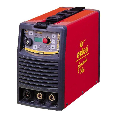
Sel Genesis 240 TLH Operating instructions

REPAIRS MANUAL
E
N
G
L
I
S
H
Genesis
240
Genesis
240 TLH

Cod. 92.08.011
Edition: 11/99
SELCO s.r.l.
Via Palladio, 19
35010 ONARA DI TOMBOLO (Padova) Italy
Tel. 0499413111
Fax 0499413311
INDEX :
1) GUARANTEE CONDITIONS
. . . . . . . . . . . . . . . . . . .84
2) PURPOSE OF THE MANUAL
. . . . . . . . . . . . . . . . . .85
3) MACHINE TECHNICAL SPECIFICATIONS
. . . . . . . .85
4) DESCRIPTION OF MACHINE PARTS
. . . . . . . . . . . .86
5) DESCRIPTION OF MACHINE OPERATION
. . . . . . .88
LAY-OUTS OF CARDS
. . . . . . . . . . . . . . . . . . . . . . .104
6) DESCRIPTION OF DIAGNOSTIC INDICATIONS :
. .116
- EXTERNAL
- INTERNAL
7) AVAILABLE SPARE PARTS
. . . . . . . . . . . . . . . . . . . .119
8) WARNINGS, PRECAUTIONS, GENERAL
INFORMATION ON EXECUTING REPAIRS
. . . . . . .121
9) DIAGNOSTIC AND REPAIR INSTRUMENTS
AND TOOLS
. . . . . . . . . . . . . . . . . . . . . . . . . . . . .121
10) DIAGNOSIS PROCEDURE :
. . . . . . . . . . . . . . . . . . .122
- LEVEL 1
- LEVEL 2
11) PARTS DISMANTLING AND RE-INSTALLATION
PROCEDURE
. . . . . . . . . . . . . . . . . . . . . . . . . . . . . . . .152
12) OPERATING TESTS AND SETTINGS
. . . . . . . . . . . .159
13) TELEPHONE ASSISTANCE
REQUEST PROCEDURE
. . . . . . . . . . . . . . . . . . . . .164
1) GUARANTEE CONDITIONS.
To specify the present warranty conditions , we remind that
SELCO does not repair under warranty the damages
a) resulting from attempts by personnel not allowed by SELCO
to install, repair or service the products
b) resulting from improper use or connection to incompatible
equipment
c) in products that have been modified or integrated with other
products when such modification or integration can be the
cause of the failure.
84 Guarantee conditions

Power supply voltage
(50/60Hz)
Max. absorbed power (x=40%)
Max. absorbed current (x=40%)
Absorbed current (x=100%)
Efficiency (x=40%)
Power factor (x=40%)
Cosj(x=40%)
Welding current (x=40%)
(x=60%)
(x=100%)
Adjustment range
Open-cicuit voltage (limited)
Protection rating
Insulation class
Construction standards
Dimensions (lxpxh)
Weight
3x400V
+10% -10%
8.4 KW
12.9 A
7.9 A
0.84
0.94
0.99
240 A
185 A
160 A
6-240 A
59 V
IP23
H
EN60974-1/EN50199
179x430x290 mm
15.4 Kg
2) PURPOSE OF THE MANUAL
The purpose of this manual is to provide authorised technical ser-
vicing centres the information required for repairing Genesis 240
and Genesis 240 TLH (see NOTE *).
To avoid serious damage to people and things, this manual must
be used strictly by qualified technicians.
What is involved in a repair job?: identifying the faulty part - as
this part is included in the list of available spare parts - and
replacing it according to the procedures described below.
If an electronic card is faulty, repair entails replacing the card
and not replacing the faulty electronic component on the card
itself.
If trouble cannot be solved by observing the procedures in the
manual, the machine must be sent back to SELCO.
We suggest two diagnosis procedures on two levels: at the first
level, simple initial action instruments/tools are used, at the
second level, more sophisticated instruments/tools are used.
By taking into account the training level of its technicians and its
available instruments, each service centre can decide whether
to use the first or second procedure.
The order of the subjects in this manual is based on a logic that
gradually provides the repair technician with knowledge of the
machine. We therefore advise you to follow the suggested
order, by starting at the beginning.
* NOTE : the information contained in this manual does not
apply to the first versions of the machine as specified
in point 10.2.
Purpose of the manual - Machine technical specifications 85
WU15
3) MACHINE TECHNICAL SPECIFICATIONS .
GENESIS 240
GENESIS 240 TLH
Power supply voltage
(50/60Hz)
Max. absorbed power in TIG
(x=40%)
Max. absorbed current in TIG
(x=40%)
Absorbed current in TIG
(x=100%)
Max. absorbed power in MMA
(x=40%)
Max. absorbed current in MMA
(x=40%)
Absorbed current in MMA
(x=100%)
Efficiency (x=40%)
Power factor
Cosj
Welding current (x=40%)
(x=60%)
(x=100%)
Adjustment range
Open-cicuit voltage (limited)
Protection rating
Insulation class
Construction standards
Dimensions (lxpxh)
Weight
3x400V
+10% -10%
6.1 KW
9.3 A
5.4 A
8.5 KW
12.9 A
7.9 A
0.84
0.94
0.99
240 A
185 A
160 A
6-240 A
81 V
IP23
H
EN60974-1/EN50199
179x430x293 mm
17.4 Kg
Power supply voltage
(50/60Hz)
Nominal input current
Capacity of reservoir
Cooling power
Protection rating
Dimensions (lxpxh)
Weight with liquid
1x230V
+ 10% -10%
0.8 A
1.7 l
900 W
IP23
179x430x160 mm
9.5 Kg
Above data are referred to environment al 40°C.

86 Description of machine parts
4) DESCRIPTION OF MACHINE PARTS.
G 240 consists of the following circuit parts:
(see fig. 1)
a) Master switch
b) input filter for suppressing radio noise and protecting against
mains over-voltage.
c) rectifier bridge
d) power inverter with overtemperature detection device
e) resonant circuit (inductive-capacitive circuit)
f) power transformer
g) rectifier circuit with overtemperature detection device
e) snubber circuit
h) output filter
i) levelling inductance with overtemperature detection device
j) current transducer (Hall effect probe)
k) fan
l) auxiliary transformer
m) power circuits feeding control/adjustment circuits
n) current control circuits
o) control circuits (front panel)
Some of these parts are independent, while others are housed
inside the following electronic cards:
G 240 :
A) Card 15.14.254
B) Card 15.14.239
C) Card 15.14.233
D) Card 15.14.240
E) Card 15.14.238
k)
a)
o) l)
i)
j)
d) e) f) g) h)
e)
c)
n)
m)
b)
FIG. 1

Description of machine parts 87
In the TLH version, the following elements are also present in
addition to the above circuits:
(see fig. 2)
p) H.F. transformer
q) H.F. discharge generation
r) gas solenoid valve
s) cooling unit power supply circuits
Some of these parts are independent, while others are housed
inside the following electronic cards:
G 240 TLH :
F) Card 15.14.254
G) Card 15.14.236
H) Card 15.14.233
I) Card 15.14.240
J) Card 15.14.238
K) Card 15.14.192
n)
m)
k)
a)
o)
q)
r)
l)
c)
b)
i) p)
j)
d)s) e) f) g) h)e)
FIG. 2

88 Description of machine operation
5) DESCRIPTION OF MACHINE OPERATION.
The power undergoes initial AC/DC conversion by the input
rectifier bridge (c) , subsequent AC/DC conversion at high fre-
quency by the inverter (d) , transfer via the insulation transfor-
mer (f) to the output circuits and final AC/DC conversion by the
output rectifier (g) .
More details:
5.1)
Master switch (a) - input filter for suppressing radio noise
and protecting against power line over-voltage (b) .
(see fig. 3-4)
The three power supply cables are cut off by means of the
switch a). The yellow-green cable is fixed to the terminal mar-
ked by the earth symbol and located on the intermediate metal
support.
IMPORTANT !: When accessing parts inside the
machine, remember that turning off the switch will
not prevent the danger of electric shocks. We the-
refore advise you to remove the power plug.
When the switch is closed, the input voltage is applied to the
board 15.14.233 containing the line overvoltage suppressor cir-
cuit (b), consisting of three varistor (see note), and the radio
interference suppressor circuit (b) (see note) connected to earth
via a screw and metal column.
n)
m)
k)
a)
o)
q)
r)
l)
c)
b)
i) p)
j)
d)s) e) f) g) h)e)
NOTE : If the electrical component know as a varistor is placed
between the two power supply phases, when an instantaneous
voltage in excess of 460 V appears on its terminals, the varistor
very rapidly becomes conductive, absorbing a current peak
which is sufficient to limit the said over-voltage and it thus pro-
tects the other parts of the machine.
This process has no destructive effect on the component if the
energy generated by the voltage peak is low, as in the case of
atmospheric lightning strikes. If, however, over-voltage is high
and prolonged, the varistor cannot dissipate this high energy
and blows.
This happens if, for example, the machine is wrongly connected
to 460 Vac mains voltage, or following over-voltage caused by
non stabilised power units of inadequate capacity.
FIG. 3

Description of machine operation 89
NOTE : The radio noise suppression circuit has two purposes:
to keep the machine's radio frequency emissions within limits
specified by standards and to ensure G 240's immunity against
the same type of problems caused by any electronic devices
connected to the same power supply source.
The filter consists of a network of capacitors, some of which are
grounded, and a toroidal inductor.
k)
a)
o) l)
i)
j)
d) e) f) g) h)
e)
c)
n)
m)
b)
FIG. 4

90 Description of machine operation
5.2)
rectifier bridge (c) - power inverter with overtemperature
detection device (d) - resonant circuit (inductive-capacitive
circuit) (e) - power transformer (f)
(see fig. 5-6)
The three-phase power supply voltage is applied to the rectifier
bridge (c), the output of which is connected to the power inverter
(d) via cables no.22(+) and no.23(-).
The inverter has a bridge type structure with four power IGBTs
(one on each branch) welded directly to board 15.14.254 and
fixed to the aluminium radiator by means of screws.
The resonant circuit (inductive-capacitive circuit) at the inverter
output terminals and the presence of an auxiliary circuit on
board 15.14.254 permit operation at high (variable) frequency.
The auxiliary circuit consists of two IGBTs and two power
diodes fixed on the aluminium radiator by means of a profiled
plastic bar, but electrically insulated from the radiator by a strip
of insulating tape with low thermal resistance.
The IGBT switch-on control circuit is located on board
15.14.254.
The radiator is cooled by the air flow generated by the fan (k)
powered at 230Vac. This voltage is insulated from the mains by
means of the auxiliary transformer (l) and protected by a fuse on
board 15.14.233. The air flows from the rear grille (air inlet) of the
machine towards the front grille (air outlet). The inverter is
protected against overloads or blocking of the ventilation air flow
by a radiator temperature detection device; this device sends a
signal to the control logic which then locks the inverter and signals
the fault to the front panel.
The power transformer (f), positioned in series with the inducti-
ve-capacitive load, transfers the power to the output circuits
which are therefore electrically insulated from the power supply
network.
k)
a)
o) l)
i)
j)
d) e) f) g) h)
e)
c)
n)
m)
b)
FIG. 5

Description of machine operation 91
n)
m)
k)
a)
o)
q)
r)
l)
c)
b)
i) p)
j)
d)s) e) f) g) h)e)
FIG. 6

92 Description of machine operation
5.3)
rectifier circuit with overtemperature detection device and
snubber circuit (g) - output filter (h) - levelling inductance with
overtemperature detection device (i).
(see fig. 7-8)
The power transformer output is connected to the two current
rectifier diodes fixed on the aluminium radiator by means of
screws.
Like the inverter, the radiator is cooled by the air flow genera-
ted by the fan. The rectifier circuit is protected against overloads
or blocking of the ventilation air flow by a radiator temperatu-
re detection device; this device sends a signal to the control
logic which then locks the inverter and signals the fault to the
front panel.
The diodes are connected to board 15.14.240 by means of cop-
per bus-bars containing the snubber circuit (g) , the function of
which is to suppress the overvoltages produced at the ends of
the diodes during normal operation.
The output board 15.14.238 contains the output filter (h) .
The levelling inductance (i) at the output guarantees a constant
welding current. The inductance is also thermally protected by
means of a winding temperature detection device which opera-
tes as described above.
k)
a)
o) l)
i)
j)
d) e) f) g) h)
e)
c)
n)
m)
b)
FIG. 7

Description of machine operation 93
n)
m)
k)
a)
o)
q)
r)
l)
c)
b)
i) p)
j)
d)s) e) f) g) h)e)
FIG. 8

94 Description of machine operation
5.4)
Current transducer (Hall effect probe) (j) - power circuits
for command/control circuits (m) - current control circuits (n).
(see fig. 9-10)
G 240 is essentially a direct current generator that can be set by
a potentiometer on the front panel. To perform this function, the
current delivered is measured by a current transducer (j); the
power cable connected to the power source output negative
terminal (-) runs through the transducer.
The control circuit on card 15.14.254 instantly compares the
value of requested and delivered current and sends the control
signal to the inverter modulator .
This control circuit also measures the machine's output current
to provide the following functions:
G 240 :
- in MMA :
increase of current when welding is started (hotstart); the
following relation applies:
supplied current = requested current + 80% of the same
increase of current if the electrode is short-circuited on the
piece during welding (arc-force); the current increase
percentage can be adjusted from 0% to 100% via the panel
potentiometer.
over-heating protection if, in spite of arc-force the short-
circuit of the electrode on the piece continues for a few tenths
of a second; the following relation applies:
supplied current = 30 A about
- in TIG (LIFT) :
limitation of no-load voltage to approximately 61 Vdc
(measurement with tester set to Vdc)
limitation of the current to 30A during the electrode short cir-
cuit phase and until the electrode is lifted.
FIG. 9
k)
a)
o) l)
i)
j)
d) e) f) g) h)
e)
c)
n)
m)
b)

Description of machine operation 95
G 240 TLH :
- in MMA : Same as the G 240 version but, in this case, in
addition to the arc force current increase percentage, the hot
start percentage can also be adjusted from 0% to 100% via the
panel (both with the setup function).
- in TIG (lift) : same as version G 240 .
- in TIG (H.F.) : initial current increase following triggering of
H.F. (fixed value).
An inverter protection circuit is also present which blocks
modulation when the power supply line voltage drops below or
oversteps the 310 Vac - 470 Vac range for a few seconds. If the
line voltage returns within the permitted limits, re-set occurs
automatically after a few seconds in the case of the G 240; to
re-set the G 240 TLH, press any button on the front panel.
All the machine electronic circuits are powered by the voltages
produced by a switching power supply on board 15.14.254, the
input of which is supplied with a voltage of 230 Vac via the auxi-
liary transformer (l).
With respect to GNDL reference potential, the following
voltages are generated:
+17Vdc
+5Vdc
-10Vdc
+15Vdc
-15Vdc
The +5Vdc power supply is supplied also to board 15.14.239
(G 240 front panel) for control of the leds.
The +15Vdc and -15Vdc power supplies are supplied also to
current transducer (Hall effect probe) and to board 15.14.236
(G 240 TLH front panel).
FIG. 10
n)
m)
k)
a)
o)
q)
r)
l)
c)
b)
i) p)
j)
d)s) e) f) g) h)e)

96 Description of machine operation
5.5)
Control circuits ( front panel ) (o).
(see fig. 11-12)
G 240 (FP104)
These circuits, which are contained in card 15.14.239 fitted at
the rear of the machine front panel, enable the following:
- setting of welding current by means of the potentiometer
- setting of welding current increase percentage via potentiometer
- selection of function mode MMA / TIG (LIFT)
When the selector switch is in MMA (low) position, open circuit
voltage is available on the machine terminals when it is powe-
red, and further, the hot-start, arc-force, and overheating
protection functions are all enabled.
When the selector switch is in TIG (high) position, open circuit
voltage increases when the machine is powered and, further-
more, current is limited to 30 A while the electrode is short-cir-
cuited and until it is raised.
Two leds are present with diagnostic functions.
Moreover, a potentiometer for setting delivered current are fit-
ted on card 15.14.239, but can be accessed only when the
machine is open.
k)
a)
o) l)
i)
j)
d) e) f) g) h)
e)
c)
n)
m)
b)
FIG. 11

Description of machine operation 97
G 240 TLH (FP106)
These circuits, which are contained in card 15.14.236 fitted at the rear of the machine front panel, enable the following:
- selection of MMA / TIG LIFT / TIG H.F. operating mode
- selection of TIG 2T (=2-strokes)/ TIG 4T (=4-strokes) / TIG BILEVEL operating mode
- selection of TIG DC / TIG pulsed / TIG medium frequency operating mode
- setting of the parameters according to the table
- selection of internal reference / remote control reference
n)
m)
k)
a)
o)
q)
r)
l)
c)
b)
i) p)
j)
d)s) e) f) g) h)e)
FIG. 12
Parameter
Pregas time
Initial current
Increase time tu
Welding current I
Back current Ib
Pulse time tp
Frequency tp & tb
Back time tb
Decrease time td
Final current If
Post-gas time
Hot-Start
Arc-Force
I max. external
I min. external
I2 in Bilevel
mu
sec.
%
sec.
A
A
sec.
Hz
sec.
sec.
A
sec.
%
%
A
A
A
min
0.0
2
0.0
6
6
0.02
20
0.02
0.0
6
0.0
0
0
6
6
6
max
25.0
200
10.0
240
240
2.00
500
2.00
10.0
240
25.0
100
100
240
240
240
predef.
0.0
50
1.0
100
20
0.25
100
0.25
1.0
8
1.0
80
30
240
6
50
Note
It can be set from setup only
Percentage on the welding current, setup only
Adjustable from the front panel
Pulsed only adjustable from the front panel
Slow puised only adjustable from the front panel
In fastpulse only, adjustable from the front panel
Slow pulsed only adjustable from the front panel
Adjustable from the front panel
MMA, it can be set from setup only
Adjustable from front panel and setup mode
Adjustable only from the setup mode
Adjustable from the front panel

98 Description of machine operation
The connector for connection of the RC16 and RC12 remote
controls is also provided.
For operation in MMA, see previous directions.
With the selector set to TIG H.F., operation is as follows.
With the selector set to TIG 2-strokes, the sequence is as fol-
lows:
1st stroke - Torch button pressed: opening of gas solenoid
valve and, after a settable pre-gas time, triggering of H.F. (if
the arc is not sparked, the H.F. is maintained for approxima-
tely 1.5 sec) and power command (possible slope-up).
2nd stroke - Torch button released: current descent ramp
followed by inverter switch-off while the solenoid valve is
kept open for a variable time (post-gas time).
With the selector set to TIG 4-strokes, we have the following
sequence:
1st stroke - Torch button pressed: gas solenoid valve opens.
2nd stroke - Torch button released: H.F. triggered (if the arc is
not sparked, the H.F. is maintained for approximately 1.5
sec.) and power command (possible slope-up).
3rd stroke - Torch button pressed: current descent ramp fol-
lowed by inverter switch-off while the solenoid valve is kept
open.
4th stroke - Torch button released: the solenoid valve is kept
open for a variable time (post-gas time).
With the selector set to TIG bilevel the sequence is as follows:
1st stroke - Torch button pressed: opening of gas solenoid
valve and, after a settable pre-gas time, triggering of H.F. (if
the arc is not sparked, the H.F. is maintained for approxima-
tely 1.5 sec) and power command with welding current level
equal to initial current (= % of welding current).
2nd stroke - Torch button released: welding current level
equal to level set I (possible slope-up).
Bilevel - Torch button pressed and immediately released: wel-
ding current level equal to I2 (without slope).
Bilevel - Torch button pressed and immediately released: wel-
ding current level equal to I (without slope).
.
3rd stroke - Torch button pressed: current slope down. At the
end of slope down, the current is maintained equal to the
final current If.
4th stroke - Torch button released: the inverter switches off
and the solenoid valve is kept open for a variable time (post-
gas time).
With the selector set to TIG LIFT, operation is the same as TIG
H.F. with the following variations in the initial triggering phase.
With the selector set to TIG 2-strokes:
1st stroke - Torch button pressed and torch in contact with piece:
opening of gas solenoid valve and, after a settable pre-gas time,
power command with current limited to approximately 30A (the
current reaches the set level when the electrode is lifted).
With the selector set to TIG 4-strokes:
1st stroke - Torch button pressed and torch in contact with
piece: opening of gas solenoid valve.
2nd stroke - Torch button released: power command with
current limited to approximately 30A (the current reaches the
set level, possibly with slope up, when the electrode is lifted).
With the selector set to TIG bilevel the sequence is as follows:
1st stroke - Torch button pressed and torch in contact with the
piece: opening of gas solenoid valve and, after a settable pre-gas
time, power command with current limited to approximately
30A.
When the torch is raised the welding current reaches the
initial current value (=% of welding current).
On board 15.14.236, but accessible only with the machine
open, there is also a welding current maximum calibration
potentiometer with reference provided by the remote control.
The torch button command arrives at the same board
(15.14.236). This command is electrically disconnected by relay
from the electronic control and adjustment circuits.
The board generates the following voltages inside (referring to
different grounds):
+5 Vdc (command circuits power supply)
+24 Vdc (torch button insulation relay power supply)
+5 Vdc (remote controls RC12 and RC16 power supply)
converting the input voltages supplied by the auxiliary transformer (l):
9Vac
24 Vac
It also receives the voltages (ground with same +5 Vdc power
supply as above command circuits) :
+15 Vdc
-15 Vdc
from board 15.14.254 .

Description of machine operation 99
n)
m)
k)
a)
o)
q)
r)
l)
c)
b)
i) p)
j)
d)s) e) f) g) h)e)
FIG. 13
5.6)
H.F. transformer. (p) - H.F. discharge generation (q).
(see fig. 13)
The H.F. discharge generation circuit (board 15.14.192) and the
H.F. transformer create a series of high voltage pulses (a few
thousand volts) to spark the TIG H.F. welding arc. These pulses
are repeated for a maximum of approximately 1.5 sec. until the
current is triggered.

100 Description of machine operation
n)
m)
k)
a)
o)
q)
r)
l)
c)
b)
i) p)
j)
d)s) e) f) g) h)e)
FIG. 14
5.7)
cooling unit power supply circuits (s).
(see fig. 14)
They consist of switches (relay and triac) via which the 230 Vac
power supply voltages from the auxiliary transformer (l) are
supplied to the pump and fan of the cooling unit WU15 during
TIG operation. The power supplies are removed if MMA
operation is selected or if no TIG welding has been performed
for a few minutes.
The command for these circuits comes from the front panel FP106.

Description of machine operation 101
k)
a)
o) l)
i)
j)
d) e) f) g) h)
e)
c)
n)
m)
b)
FIG. 15
5.8)
auxiliary transformer (l).
(see fig. 15-16-17)
Provides the power supplies at the electronic board inputs.
It also provides the 230 Vac power supply voltages for the fans
(power source and cooling unit) and pump.
Fig. 17 illustrates the path of the above 230 Vac voltages.

102 Description of machine operation
n)
m)
k)
a)
o)
q)
r)
l)
c)
b)
i) p)
j)
d)s) e) f) g) h)e)
FIG. 16
F1
F2
FIG. 17
Table of contents
Other Sel Welding System manuals

Sel
Sel WFR 20 User manual

Sel
Sel Neomig 3500 User manual

Sel
Sel Genesis 3200 TLH User manual

Sel
Sel Genesis 4000 PSR User manual

Sel
Sel Quasar 320 MSE User manual

Sel
Sel RI2000 User manual

Sel
Sel Genesis 1700 AC/DC Operating instructions

Sel
Sel Genesis 3200 MSE User manual

Sel
Sel Genesis 4000 TLH User manual

Sel
Sel Genesis 2700 TLH User manual

Sel
Sel Genesis 35 Operating instructions

Sel
Sel Saber 70 chp User manual

Sel
Sel Genesis 1100 Operating instructions

Sel
Sel Genesis 1500 TLH User manual

Sel
Sel Genesis 60 User manual

Sel
Sel Genesis 2200 MTE User manual

Sel
Sel Genesis 302 AC/DC Operating instructions

Sel
Sel Genesis 302 AC/DC User manual

Sel
Sel Genesis 90 Operating instructions

Sel
Sel Genesis 60 User manual