Sena Parani10 User manual

1
Parani10
Enabling Wireless Serial Communication
UsersGuide
Version 1.0.0
2005-03-07

2
Copyright Information
Copyright 1998-2004, Sena Technologies, Inc. All rights reserved.
Sena Technologies reserves the right to make any changes and improvements to its product
without providing prior notice.
THIS DEVICE COMPLIES WITH PART 15 OF THE FCC RULES.
Operation is subject to the following two conditions;
(1) this device may not cause harmful interference, and
(2) this device must accept any interference received, including interference that may cause
undesired operation.
CAUTION: Changes or modifications not expressly approved by the party responsible for
compliance could void the user’s authority to operate the equipment.
Trademark Information
Parani™. is a trademark of Sena Technologies, Inc.
Windows® is a registered trademark of Microsoft Corporation.
Ethernet® is a registered trademark of XEROX Corporation.
Notice to Users
Proper back-up systems and necessary safety devices should be utilized to protect against
injury, death or property damage due to system failure. Such protection is the responsibility of
the user.
This device is not approved for use as a life-support or medical system.
Any changes or modifications made to this device without the explicit approval or consent of
Sena Technologies will void Sena Technologies of any liability or responsibility of injury or loss
caused by any malfunction.
Technical Support
Sena Technologies, Inc.
210 Yangjae-dong, Seocho-gu
Seoul 137-130, Korea
Tel: (+82-2) 573-5422
Fax: (+82-2) 573-7710
E-Mail: [email protected]
Website: http://www.sena.com

3
Revision History
Revision Date Name Description
V1.0.0 2005-03-02 D.H. Shin Initial Release

4
Table of Contents
1. Introduction........................................................................................................................ 6
1.1 Overview................................................................................................................................6
1.2 Package Check List................................................................................................................6
1.3 Product Specification..............................................................................................................8
2. Getting Started ................................................................................................................... 9
2.1 Lamps....................................................................................................................................9
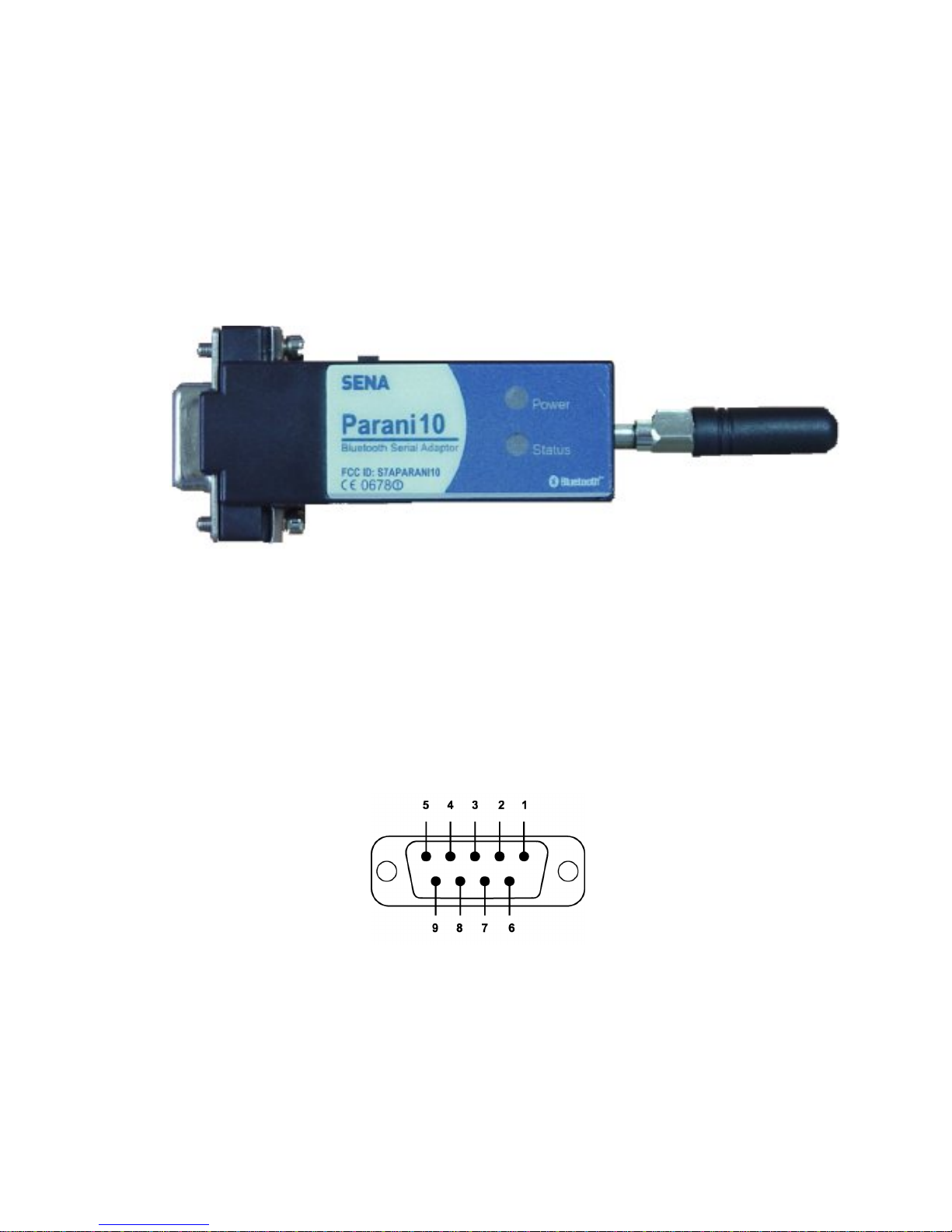
2.2 RS232 Interface....................................................................................................................10
2.3 Connecting Parani10 to host.................................................................................................12
3. Configuration.....................................................................................................................13
3.1 Using Parani10 Manager.......................................................................................................13
3.1.1 Let’s make P01 to be discoverable/connectable 13
3.1.2 Let’s make P02 search and connect to P01 16
3.1.3 Let’s make Auto-Connection between P01 and P02 17
3.2 Using a Terminal Program.....................................................................................................20
3.2.1 Connecting Parani10 to host 20
3.2.2 Making the first Parani10/Bluetooth connection 20
3.2.3 Making Parani10 do INQUIRY SCAN and PAGE SCAN 21
3.2.4 Releasing the existing Bluetooth connection 22
3.2.5 Automatic connection of two Parani10 Units 23
3.2.6 AT command vs. Operational Status 24
4. For Multi-Serial Connections............................................................................................26
4.1 Parani100.............................................................................................................................26
Appendix A: AT command sets............................................................................................27
AT<cr> 27
ATZ<cr> 27
AT&F<cr> 27
AT+BTINQ?<cr> 27
ATD BD_ADDR <cr> 28
ATD<cr> 28
AT+BTSCAN <cr> 28
AT+BTSCAN, n, to<cr> 29
AT+BTSCAN, BD_ADDR, to<cr> 29
AT+BTCANCEL<cr> 29

5
+++ 30
ATO<cr> 30
ATH<cr> 30
AT+BTSEC, Authentication, Encryption <cr> 30
AT+BTLAST?<cr> 31
AT+BTMODE, n<cr> 31
AT+BTNAME=”FriendlyName”<cr> 31
AT+BTKEY=”nnnn”<cr> 31
AT+BTINFO?<cr> 32
AT+BTLPM,n<cr> 32
AT+BTSD?<cr> 32
AT+BTCSD<cr> 33
AT+BTFP,n<cr> 33
AT+UARTCONFIG, baudrate, parity, stopbit,handshaking<cr> 33
Full AT commands set 33
Appendix B: Power Adaptor Specification...........................................................................39
Appendix C: Troubleshooting ..............................................................................................42
C.1 ON/OFF of Hardware Flow Control.......................................................................................42
C.2 Enabling/Disabling of Response Signals OK, CONNECT & ERROR......................................43
C.3 For DCE connection.............................................................................................................44
C.4 Hardware Reset...................................................................................................................44
C.5 How to get Bluetooth CF cards connected to Parani10..........................................................44

6
1. Introduction
1.1 Overview
Parani10 is a wireless serial adapter based on Bluetooth technology. It enables the RS232
serial devices to communicate wirelessly throughout the range of 200m ~ 1.2km. It supports
both point-to-point connectionsand point-to-multipoint connections.
Users may configure the Parani10 by using an easy-to-use Windows-based utility software or
by using a standard AT command set.
Parani10 allows users to choose various power supply options, i.e. Power by DC power cable,
Power by external DC-adapter, Power by USB power cable, Power by pin 9 of DB9 connector.
Typical application areas of the Parani10 include:
•RS232 cable replacement
•Truck/Bus monitoring system
•Car Diagnostics
•Wireless POS system
•Wireless Factory monitoring
•PLC programming
•Wireless machine (healthcare/industrial) monitoring
•Wireless Printing
•Wireless logistics
1.2 Package Check List
-DC Power cable
-Dipole antenna
-CD-ROM, including the Parani10_Manager software and manual.

7
Fig. 1.2.1DC Power Cable
*Red colored wire of DC power cable is for ‘+’

8
1.3 Product Specification
Serial Interface:
RS232, Female DB9, 1200~230 Kbps
Automatic detection of hardware flow control
DTR/DSR for loop-back & full transfer
Bluetooth Interface:
Bluetooth v1.1
Class I
Protocols –RFCOMM, L2CAP, SDP
Profiles -General Access Profile, Serial Port Profile
Working distance
Default Antenna -Default Antenna up to 200m
Patch Antenna -Default Antenna up to 400m
Patch Antenna -Patch Antenna up to 1200m
Configuration:
Windows Utility, Parani10 Manager
Modem AT command set
Diagnostic LED:
Status and Power LED
Power:
4V~12V, minimum 150mA
Nominal power consumption of 40mA@9600bps and 72mA@115Kbps speed
Power supply options
Power via a standard AC-plug DC-adapter
Power via USB power cable
Power via DC power cable
Power via pin 9 of DB9 connector

9
Environmental:
Operating temperature: 5?to 50?
Storage temperature: -4?to 66?
Humidity: 90% Non-condensing
Physical properties:
Dimension (L x W x H) 96 x 31 x 16 (mm), 3.8 x 1.2 x 0.6 (in.)
Weight 14g
Approvals:
Bluetooth 1.1
FCC(A), CE, TELEC
Warranty:
5-year Limited Warranty
2. Getting Started
2.1 LED Indicators
The Parani10 STATUS LED indicates the following:
Lamps Description
Amber Standard mode on Parani10 power-up
Solid Green Connected to another Bluetooth device
Green Flashing
At 1 sec interval INQUIRY operation
STATUS
Green Flashing
At 3 sec interval INQUIRY SCAN or PAGE SCAN operation
POWER Green Power is being supplied

10
Figure 2.1.1 Parani10
2.2 RS232 Interface
Parani10 has a DB-9(female) connector as shown below in Fig 2.2.1
Figure 2.2.1. DB-9(Female)
•The serial interface is RS232 DCE configured; a DTE device can be connected.
•Baud rate: 1200~230400bps
•Hardware flow control (RTS/CTS)

11
Pin Signal Direction
1CD Output
2TxD Output
3RxD Input
4DSR Input
5GND -
6DTR Output
7CTS Input
8RTS Output
9Vcc Input
Table 2.2.1. Parani10 DB-9Specification
Parani10 is designed to operate as DCE (Data Communications Equipment).
To connect to DTE (Data Terminal Equipment), for example a PC or a laptop, a straight cable
must be used as in below.
CD, 1 CD, 1
TxD,
2
RxD, 2
RxD,
3
TxD, 3
DSR,
4
DTR, 4
GND,
5
GND, 5
DTR,
6
DSR, 6
CTS,
7
RTS, 7
Parani10 (DCE)
RTS,
8
CTS, 8
Host System (DTE)

12
*DTR/DSR of Parani10 will function for either a Loop-back operation or for full transfer. Users
may select a function of DTR/DSR using AT command-ATS14. Default value of ATS14 is 1.
•ATS14=1<cr>: Default setting. Users may use DTR/DSR lines for communications
•ATS14=0<cr>: Users may use DTR/DSR lines for Loop-back only.
•ATS14? : To see current status of ATS14.
*Default setting of CD line in Parani10 is to show the status of Bluetooth connection. If users
want to use CD line to send CDC signal to the other side, such as for a connection between
Parani10 and DCE device, users need to configure ATS13.
•ATS13=0<cr>: Default setting. Users may use CDC line for checking a Bluetooth connection.
•ATS13=1<cr>: Users may receive CDC signal from other Parani10.
(This function will be available from future version of Parani10 for DCE devices)
•ATS13 ?: To see current status of ATS13.
2.3 Connecting Parani10 to host
Step 1. Connect a Parani10 to a serial port of the host computer.
Step 2. Supply power by using one of the following methods:
Power via DC power cable
Power via a standard AC-plug DC-adapter (Option)
Power via USB power cable (Option)
Step 3. Turn on the Parani10 power by using the switch on the side.
Step 4. Check the LED lamps.
The Power LED must display a solid green color, to indicate that power is being supplied
properly.
Step 5. Proceed with the steps for the configuration to make Parani10 work.
See Chapter 3. Configuration for details.

13
3. Configuration
3.1 Using Parani10 Manager
With Parani10, Bluetooth wireless connections can be made to any Bluetooth device
supporting SPP (Serial Port Profile). Especially when using the Parani10 as a cable
replacement, take advantage of the Parani10 automatic connection feature. Once a pair of
Parani10’s is set for this feature, they automatically connect whenever powered up. A pair of
Parani10 units, within their radio range, may be used as a virtual RS-232 cable.
To allow wireless connections between two Bluetooth devices, one device should be in
Discoverable (INQUIRY SCAN) and Connectable (PAGE SCAN). Most Bluetooth devices are
set to Discoverable and Connectable by the manufacture. However, to allow Parani10 to
respond to the INQUIRY and PAGE operations of other Bluetooth devices, INQUIRY SCAN and
PAGE SCAN modes will need to be activated.
Before making the first Bluetooth connection with Parani10 units, be prepared with a pair of
Parani10 units and also install the Parani10_Manager program on the CD enclosed in the
Parani10 product package.
*Configuration By Parani10_Manager
Please prepare two of the Parani10s to make connection.
Let’s say 1st unit as ‘P01’ and 2nd unit as ‘P02’ in this guide book. Make sure that power to both
P01 and P02 are ALWAYS supplied, even when you detach from your computer.
3.1.1 Let’s make P01 to be discoverable/connectable.
In this procedure, P01 will become discoverable/connectable to be able to receive connection
from P02.
1-1. Attach P01 to your PC, and start Parani10_Manager
1-2. Start Parani10_Manager then you will see a pop-up window for configuration of
Parani10_Manager.

14
<Fig. 3.1.1>
1-3. Select the number of the Serial port where P01 is attached as in the Fig. 3.1.1 above.
1-4. Users need to select exactly same Baud/Parity/StopBit as real settings of attached P01.
9600/No/OneStopBit are default initial settings of all of Parani10s.
1-5. Press OK button when finished.
1-6. Open ‘Parani10_Manager->Start Configuration’ on the upper left menu.
Parani10_Manager will bring the information on the attached P01 as in Fig. 3.1.2
<Fig. 3.1.2>

15
1-7. Click the ‘Device Setting’ icon in the list control box. Users may change the Baud
rate/Parity/StopBit to meet their individual needs.
<Fig. 3.1.3>
1-8. Click the ‘Connection(in)’ icon in list control box. Check both options and then click the
START button as shown in Fig. 3.1.4.
<Fig. 3.1.4>

16
1-9. P01 now became ‘Discoverable/Connectable’ so it can receive Bluetooth connection from
P02. The STATUS LED of P01 will blink green, twice every 3 seconds.
1-10. Detach P01 from your computer, making sure its status LED is blinking green.
1-11. Close Parani10_Manager.
3.1.2Let’s make P02 search and connect to P01.
2-1. Attach P02 to your PC, and start Parani10_Manager.
2-2. Select the number of the Serial port where P02.
2-3. Users need to select exactly same Baud/Parity/StopBit as the setting of attached P02.
9600/No/OneStopBit is default setting of all of Parani10s.
2-4. Press OK button.
2-5. Select the ‘Connection(out)’ icon in the list control box and click the SEARCH button.
<Fig. 3.1.5>
2-6. Search P01 from the searched list. Device Address of P01 can be found on the back side of
P01. If you find P01, press Cancel button to finish searching.
Make sure that Status LED of P01 is still blinking in Green.
2-7. Please select P01 from the searched list, then press CONNECT TO button.

17
2-8. You will get Successful Connection message.
<Fig. 3.1.6>
2-9. Now, Status LEDs on Both P01 and P02 are Green, which means they are connected.
2-10. Do not detach P02 from your computer yet, we will go to next stage for Auto-connection
(Always-connection).
3.1.3 Let’s make Auto-Connection between P01 and P02
3-1. With P02 which is still attached to your computer, in Connection(out) page,
press the DISCONNECT button at the bottom to release the connection for a while.
P02 will remember the last-connected device, even after disconnection.
<Fig. 3.1.7>

18
3-2. Now, Status LEDs of P02 becomes ‘Orange’, as well as P01, as they are disconnected.
3-3. Select Device Setting icon in the list control box, and select MODE1 in Operation Mode and
apply.
<Fig. 3.1.8>
3-4. Now jobs for P02 are finished. Detach P02from your computer.
3-5. Attach P01 to your computer.
3-6.Restart Parani10_Manager.

19
3-7.Select Device Setting icon in the list control box, and select MODE2in Operation Mode and
apply.
<Fig. 3.1.9>
3-8. Now, detach P01 from your computer.
3-9. Make sure that power to Both P01 and P02 are supplied.
With both, P01 and P02, turn off both units using the Switch located on the side of its body.
Then, turn on both P01 and P02 almost at the same time.
Now, you will see Green Status LEDs on both units.
P01 and P02 will be connected automatically, as long as the configuration for both units remains
unchanged.

20
3.2 Using a Terminal Program
Parani10 units are easily controlled and configured via Parani10_Manager. Likewise, AT
command sets are supported by Parani10 to allow device control capabilities used by the
terminal program of your choice.
3.2.1 Connecting Parani10 to host
For Parani10 use, follow the simple instructions below:
1. Connect a Parani10 to a host serial port. Then, turn on the Parani10.
2. Check the STATUS LED color. Amber indicates standard mode.
3. Execute any terminal program and activate Local Echo.
4. Configure the host serial port to match the Parani10 unit configuration. The
Parani10 default configuration is 9600 bps Baud, 8 Data bit, No Parity, 1
Stop bit and H/W flow control.
5. Enter ‘AT’ command at the prompt. A Parani10 ‘OK’ reply indicates proper
operation.
3.2.2 Making the first Parani10/Bluetooth connection
As stated before, Bluetooth wireless connections can be made with any
other Bluetooth device supporting Bluetooth SPP (Serial Port Profile).
For Bluetooth wireless connections to a Parani10, first make another
Parani10 ‘Discoverable’ and ‘Connectable’. In this case, refer to
section 3.2.3 before following the instructions below.
1. First check the status of the Parani10 by entering ‘AT+BTINFO?’. The
Parani10 response is comprised of BD_ADDR, Device Name, Operating
Mode, Operating Status, Authentication and Encryption flags. To make a
connection to other Bluetooth devices, the operating status of the first
Parani10 should be ‘STANDBY’. A ‘PENDING’ operating status of the first
Parani10 indicates the unit is busy with another operation. In this case,
cancel the ongoing operation by entering the ‘AT+BTCANCEL’ command.
Table of contents
Other Sena Adapter manuals

Sena
Sena Parani UD100 User manual

Sena
Sena Bluetooth Audio Pack for GoPro User manual

Sena
Sena FREEWIRE User manual

Sena
Sena Parani-UD100 User manual

Sena
Sena Rhio232 User manual

Sena
Sena PD10 User manual

Sena
Sena Parani-SD1000 User manual

Sena
Sena SR10 User manual

Sena
Sena Parani-SD1000 User manual

Sena
Sena Parani-UD100 User manual

Sena
Sena SmartFlex SR305 User manual

Sena
Sena Parani-ESD1000 User manual

Sena
Sena ProBee-ZS10 User manual

Sena
Sena ProBee-ZS10 User manual

Sena
Sena SR10 User manual

Sena
Sena Parani-SD100 User manual

Sena
Sena Parani-SD1000 User manual

Sena
Sena FreeWire SP29 User manual

Sena
Sena Parani-SD100 User manual

Sena
Sena 50 Series User manual