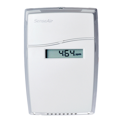
SenseAir eSENSE User manual

EM eSENSE_all_housings_May'08.doc
1 of 10
Installation Manual for All Housings
eSENSE
eSENSEeSENSE
eSENSE™
(-D)
CO
2
transmitter
eSENSE™
eSENSE™eSENSE™
eSENSE™-
--
- D
D D
D
eSENSE™
eSENSE™eSENSE™
eSENSE™-
--
- K
K K
K
and
eSENSE™
eSENSE™ eSENSE™
eSENSE™-
--
- Ip54
Ip54 Ip54
Ip54
General
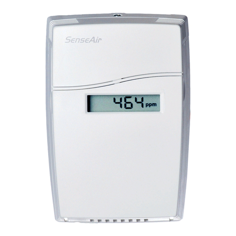
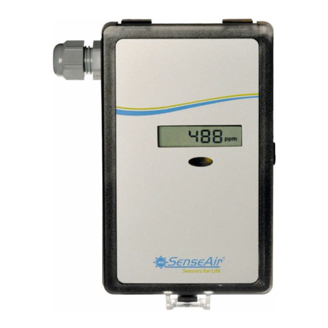
The IAQ-sensor product
e
ee
eSENSE
(sensor for wall mounting) is designed to measure carbon
dioxide (CO
2
) in rooms. Option
- Tr
is prepared for temperature measurements by the
resistive temperature probe mounted by the user. The temperature probe is potential free
(floating). Option
- D
displays the measured CO
2
value in ppm (parts-per-million) on the
LCD.
The units are designed for connecting to Direct Digital Control (DDC) with 0-10V or
2-10V signal inputs. The two parallel signal outputs OUT1 (0-10V) and OUT2 (2-10V or 4-
20 mA) give linear signal voltages or currents corresponding to the measuring range.
The output OUT2 also indicates the status by setting the output voltage to 1V or the output
current to 2 mA when the sensor self-diagnostics detects any error.

EM eSENSE_all_housings_May'08.doc
2 of 10
eSENSE
eSENSEeSENSE
eSENSE™
(-D)
CO
2
transmitter for wall mounting
To open the wall mounted housing
Closed housing seen from above. Pressing
a screwdriver on the locking hook opens
the housing. The locking hook is then
released.
Dimensions and holes
80(3,15)
28(1,10)
30(1,18)
60(2,36)
4(0,16) 4(0,16)
30(1,18)
100(3,94)
The dimensions of the sensor in mm and (inches)
Press here to open.

EM eSENSE_all_housings_May'08.doc
3 of 10
eSENSE
eSENSEeSENSE
eSENSE™
(-D) -K
CO
2
transmitter for mounting in ventilation ducts
1
2
1
2
3
4
5
6
7
9
8
1 Sampling probe 6 O-ring 29,2x3,53 (Factory supplied mounted in box)
2 Sealing gasket 7 PCB (Factory supplied mounted in box)
3 Largest locking knob 8 Snap-in lid
4 2 washers BRB 5,3x10x1 9 PG9 cable entry bushing
5 2 screws RXS 4,8x16
Parts of the
e
ee
eSENSE
for duct mounting

EM eSENSE_all_housings_May'08.doc
4 of 10
Mounting of
e
ee
eSENSE
on to the duct.
10
10 Hole with 25 mm diameter
11 Temperature sensor with 110 mm cable mounted in the sampling probe
Figure 3. Mounting of the sensor to the ventilation duct
Mounting Instruction
Since there might be a substantial pressure difference in duct mounting applications, it is
essential to avoid ambient air from suction into the duct-mounting box. For correct function it
is indispensable that the sealing of the box cover, the cable entry bushings, the cable feed
through and the duct entrance are absolutely tight. The duct entrance may need extra sealing
paste in order to prevent leakage. The PCB must be handed carefully and protected from
electrostatic discharge.
1) Electrical cable entry: The box has a factory mounted cable entry bushing in dimension
PG9. Never feed more than one cable through each cable entry bushing, or else gas might
leak through!
2) Mounting the tube: Drill a hole (10) with 25 mm diameter (or 1 inch) for the sampling
probe and two holes with 4 mm diameter for the screws (5) into the air duct and mount
the tube (1) with the gasket (2). The sampling probe should be mounted with the largest
locking knob on top. The unit can be mounted with the air coming from the left or right.
3) Attaching the sensor box is made to the sampling probe by a snap-in bayonet fitting.
Orient the box onto the sampling probe so that the box upside is on the same side as the
largest locking knob (3). When the probe is fitted into the notches of the box, then turn
the box clockwise until stop (see Figure 1). Position 1 indicates open where the box can
be removed from the sampling probe. In position 2 the box is locked to the probe
.

EM eSENSE_all_housings_May'08.doc
5 of 10
Dimensions
42(1,65)
46(1,81)
84(3,31)
141,8(5,56)
151,3(5,96)
204(8,03)
The dimensions of the sensor in mm and (inches)
The dimensions of the sampling probe in mm and (inches)
66(2,6)
55(2,16)
56(2,2)
6(0,24)

EM eSENSE_all_housings_May'08.doc
6 of 10
eSENSE
eSENSE eSENSE
eSENSE™
(-D) –IP54
CO
2
transmitter mounted in industrial housing
4
5
3
2
1
6
1 Wall plate
2 CB (Factory supplied mounted in box)
3 Hole for wall plate hooks
4 Snap-in lid
5 Locking screw of the lid (not shown)
6 Air holes

EM eSENSE_all_housings_May'08.doc
7 of 10
7
10 8910
38,5 (1,5) 10 (0,39)
85 (3,35)
141,8 (5,58)
9,5 (0,37)
7 Lid locking screw
8 Wall plate
9 Screw to hold the wall plate
10 Drill marking for cable entry bushings
Dismounting the wall plate
The sensor is delivered with the wall plate
mounted. The wall plate has to be
removed before the sensor is mounted
onto the wall. Unscrew the screw on the
side of the box.
Wall Mounting Instruction
1) Electrical cable entry: The box has a factory mounted cable entry bushing in
dimension PG9. Never feed more than one cable through each cable entry bushing, or
else gas might leak through!
2) Screw the wall plate onto the wall: The wall plate has holes for three screws. Drill
holes for 3,5mm screws and put dowel into them. Dowels and screws 3,5 x 25mm are
included in a plastic bag
3) Attaching the sensor box to the wall plate is done by a snap-in fitting. The wall plate
has three hooks that fit in holes in the sensor box. Fasten the screw on the side of the
box.
4) The lid can be locked with the screw at the bottom of the sensor box.
If for some reason the PCB must be removed it must be handed carefully and
protected from electrostatic discharge! Normally, removing the PCB is not
required.
82(3,23)
66(2,60)
41(1,61)
17,5(0,69)
40,5(1,59)
63(2,48)
Ø5(0,20)
Ø5(0,20)
Ø5(0,20)
42(1,65)
39,9(1,57)

EM eSENSE_all_housings_May'08.doc
8 of 10
Electrical connections
The power supply has to be connected to
+~
and . is considered as system ground.
The same ground reference has to be used for the
e
ee
eSENSE
unit and for the DDC/signal
receiver.
PLEASE NOTE!
The same ground reference has to be used for the
e
ee
eSENSE
unit
and for the control system!
Terminal
Function Electrical data Remarks
Standard settings Remarks
Settings of this
sensor
+~
Power (+)
Power ground (-)
24 VAC/DC+
(+-20%), 2W
24 VAC/DC-
System voltage
reference
OUT1
OUT2
Analogue output 1 (+)
Analogue output 2 (+)
0-10 VDC
2,0-10,0 VDC or
4,0-20,0 mA
0,9-1,6 VDC or
1.5-2,5 mA
0 VDC or 0mA
0-2000 ppm CO
2
0-2000 ppm CO
2
Status = ERROR
Status = NOT READY
Table I. Connections of the main terminal of
e
ee
eSENSE
Option display
+
~
Option display
+
~
PCB with jumper to configure OUT2
PCB with mounted resistor OUT2 is then
For current output 4-20mA or
configured for voltage output 2-10VDC
voltage output 2-10VDC

EM eSENSE_all_housings_May'08.doc
9 of 10
+
~
Enlarged picture of the PCB with the jumper set to current output (left position)
+
~
Enlarged picture of the PCB with the jumper set to voltage output (right position)
Self diagnostics
The system contains complete self-diagnostic procedures that are executed automatically
when the sensor is in operation. The yellow LED is lit if an error is found. Sensors with
display show a wrench if an error is found. The wrench is shown and the yellow LED is lit
during the first seconds after power up and if the measuring range exceeded. They are
automatically turned off when the sensor returns to normal operation. The output OUT2
indicates the same information by setting the output voltage to 1V or 2 mA.
Maintenance
The
eSense K50
eSense K50eSense K50
eSense K50
is basically maintenance free in normal environments thanks to the built-in
self-correcting ABC algorithm. Discuss your application with SenseAir in order to get advice
for a proper calibration strategy.
PLEASE NOTE!
The sensor accuracy is defined at continuous operation (at least 3 weeks after
installation)
PLEASE NOTE! Electronic products should be disposed of via a suitable recycling
centre.

EM eSENSE_all_housings_May'08.doc
10 of 10
WARRANTY AND LIMITATION OF LIABILITY
1. SenseAir warrants that for a period of twentyfour (24) months following receipt by Buyer
the Product supplied by SenseAir to Buyer will be, under normal use and care, free from
defects in workmanship or material and to be in material conformity with SenseAir's
specifications. Units returned to SenseAir for warranty repairs shall be shipped to SenseAir, at
Buyer’s expense, according to SenseAir's instruction. Within ninety (90) days of the receipt of
product, SenseAir shall replace or repair such units and shall ship them to Buyer’s designated
return destination freight pre paid.
2. Warranty Limitations. This warranty does not extend to any unit that has been subject to
misuse, neglect or accident; that has been damaged by causes external to the unit; that has
been used in violation of SenseAir's instructions; that has been affixed to any non-standard
Accessory attachment; or that has been modified, disassembled, or reassembled by anyone
other than SenseAir.
3. The retailer is not responsible for any consequential loss or damages, which may occur by
reason of purchase and use of this product. The warranty is, in any event, strictly limited to
the replacement/repair of the product
This product is in accordance with the EMC 2004/108/EC, 92/31/EEG including amendments
by the CE-marking Directive 93/68/EEC
The product fulfils the following demands: EN 61000-4-2 level 2,
EN 61000-4-3 level 2, EN 61000-4-4 level 4, EN 61000-4-6, EN 61000-4-8 level 4,
EN 55022 class B
Other manuals for eSENSE
2
This manual suits for next models
3
Table of contents
Other SenseAir Transmitter manuals
SenseAir
SenseAir aSENSE User manual

SenseAir
SenseAir aSENSE User manual
SenseAir
SenseAir aSENSE GH (Disp) RL User manual
SenseAir
SenseAir tSENSE VAV Disp User manual

SenseAir
SenseAir aSENSE User manual

SenseAir
SenseAir aSENSE User manual
SenseAir
SenseAir tSense User manual

SenseAir
SenseAir aSENSE User manual
SenseAir
SenseAir eSENSE Ind User manual

SenseAir
SenseAir aSENSE User manual
