Servomex 2700 User manual

Part Number: 02700005D
Revision: 7
Language: UK English
SERVOTOUGH FluegasExact 2700
INSTALLATION MANUAL


02700005D_7 © Servomex Group Limited. 2021 i
IMPORTANT INFORMATION
Continued safe and reliable operation of this equipment is conditional
on all installation, operation and maintenance procedures being
carried out in accordance with the appropriate manuals, by personnel
having appropriate qualifications, experience and training.
Failure to observe the requirements of the manual may result in the user being held responsible for the
consequences and may invalidate any warranty.
Servomex will accept no liability for unauthorised modifications to Servomex supplied equipment.
Servomex has paid particular attention to Health and Safety throughout this manual. Where special
precautions need to be taken due to the nature of the equipment or product, an appropriate safety icon and
warning message is shown. Special attention should be made to Section 1.3, where all such messages are
summarized.
In line with our continuous policy of research and development, we reserve the right to amend models and
specifications without prior notice.
This handbook is accurate at the date of printing but will be superseded and should be disregarded if
specifications or appearance are changed.
Servomex is a registered trademark of Servomex Group Limited. The use of all trademarks in this document
is acknowledged.
© 2021. Servomex Group Limited. A Spectris Company. All rights reserved

ii © Servomex Group Limited. 2021 02700005D_7
Blank page

02700005D_7 © Servomex Group Limited. 2021 iii
Contents
1Introduction ............................................................................................................................1
1.1 Warnings, cautions and notes ......................................................................................... 1
1.2Scope of this manual.......................................................................................................1
1.3 General safety information ..............................................................................................2
1.4 Hazardous Area approval and certification......................................................................3
1.5 Unpacking.......................................................................................................................3
2Analyser Overview .................................................................................................................5
2.1 Overview.........................................................................................................................5
2.2 Sensor head description ................................................................................................. 6
2.3 Control unit description ...................................................................................................6
2.4 Sample flow alarm ..........................................................................................................6
3Installation of Sensor Head and Probe Tube .......................................................................7
3.1 Installation location .........................................................................................................7
3.2 Flange mounting arrangements .................................................................................... 12
3.3 Sample probe installation.............................................................................................. 20
3.4 Calibration and utilities supplies .................................................................................... 27
3.5 Electrical installation...................................................................................................... 30
3.6 ATEX/IECEx special instructions for hazardous areas .................................................. 34
3.7 North America special instructions for hazardous areas................................................ 38
4Installation of Flow Alarm Relay Box.................................................................................. 42
4.1 Installation location .......................................................................................................42
4.2 Electrical installation...................................................................................................... 44
5Installation of Control Unit .................................................................................................. 50
5.1 Installation location .......................................................................................................50
5.2 Electrical installation...................................................................................................... 53
5.3 Enclosure purge connection.......................................................................................... 59
6Initial Startup Procedure...................................................................................................... 62
6.1 Gases required ............................................................................................................. 62
6.2 Visual inspection ...........................................................................................................62
6.3 Initial power up..............................................................................................................63
6.4 Analogue output span setup.......................................................................................... 63
6.5Sensor head sample flow adjustment............................................................................ 64
6.6 Combustibles sensor zero adjustment .......................................................................... 64

iv © Servomex Group Limited. 2021 02700005D_7
6.7 Sensor calibration .........................................................................................................64
6.8 Flow alarm calibration ................................................................................................... 65
7Maintenance and Spares .....................................................................................................69
7.1 Maintenance ................................................................................................................. 69
7.2 Replacing fuses ............................................................................................................70
7.3 Preventative maintenance.............................................................................................70
7.4 Spare parts ...................................................................................................................71
8Technical Specification ....................................................................................................... 76
8.1 Oxygen measurement performance .............................................................................. 76
8.2 Combustibles measurement performance..................................................................... 76
8.3 Flow alarm performance ...............................................................................................77
8.4 Analyser inputs and outputs .......................................................................................... 78
8.5 Physical ........................................................................................................................79
8.6 Materials in contact with sample ................................................................................... 80
8.7 Hazardous area classification ....................................................................................... 80
8.8 Sensor head purge certification labels .......................................................................... 83
9Appendix A – Interconnecting Wiring Schedules .............................................................. 86
10 Appendix B – Compliance and Standards Information ..................................................... 96
11 Appendix C – Product Disposal / Applicability of the Waste Electrical and Electronic
Equipment (WEEE) Directive...................................................................................................... 98
12 Appendix D – REACH Regulation ..................................................................................... 100
13 Appendix E – North American – Hazardous Area Installation Drawing.......................... 102

02700005D_7 © Servomex Group Limited. 2021 v
Table of Figures
Figure 1 Analyser sensor head and control unit overview ...............................................................5
Figure 2 - Sensor Head mounting orientation..................................................................................7
Figure 3 – Protect from radiant heat sources and the sun ............................................................... 8
Figure 4. Sensor head dimensions (typical) .................................................................................. 11
Figure 5. Adaptor flange installation ..............................................................................................15
Figure 6. High temperature stand-off flange installation ................................................................ 16
Figure 7. Thermal spacer installation ............................................................................................ 18
Figure 8. Probe retention flange installation .................................................................................. 20
Figure 9. Sample probe and filter construction .............................................................................. 23
Figure 10. Supported probe construction ...................................................................................... 24
Figure 11. Probe support tube installation..................................................................................... 26
Figure 12. Sensor head terminal enclosure detail ......................................................................... 33
Figure 13. Typical sample arrangement ........................................................................................ 36
Figure 14. PCS connections .........................................................................................................37
Figure 15. Flow alarm relay box installation .................................................................................. 43
Figure 16. Flow alarm relay box terminals..................................................................................... 44
Figure 17. Flow sensor signal amplifier board ............................................................................... 47
Figure 18. Control unit installation................................................................................................. 52
Figure 19. Control unit enclosure detail......................................................................................... 56
Figure 20. Flow alarm relay box components................................................................................ 65
Figure 21. Leakage compensation label........................................................................................ 83
Figure 22. Continuous flow label ...................................................................................................84
Figure 23. Oxygen sensor only interconnection wiring schematic ................................................. 88
Figure 24. Combustibles only interconnection wiring schematic.................................................... 90
Figure 25. Dual sensor interconnection wiring schematic.............................................................. 92
Figure 26. Flow alarm interconnection wiring schematic ............................................................... 94

vi © Servomex Group Limited. 2021 02700005D_7
List of Tables
Table 1. Sensor head operating environment..................................................................................9
Table 2. Sensor head adaptor flange kits...................................................................................... 14
Table 3. Sample probe part numbers ............................................................................................22
Table 4. Sensor head electrical power connections ...................................................................... 33
Table 5 - Purge control system parameters................................................................................... 38
Table 6. Flow alarm relay box operating environment ................................................................... 42
Table 7. Relay box terminal information ........................................................................................ 44
Table 8. Relay contact specification.............................................................................................. 45
Table 9. Flow alarm relay box terminals - DIRECT mode.............................................................. 45
Table 10. Flow alarm relay box terminals - INVERSE mode ......................................................... 45
Table 11. Flow sensor signal amplifier board terminal information ................................................ 47
Table 12. Control unit operating environment................................................................................ 51
Table 13. Control unit electrical power voltage selection ............................................................... 55
Table 14. Control unit electrical power connections ...................................................................... 57
Table 15. Relay output connections .............................................................................................. 58
Table 16. Analogue output connections ........................................................................................ 58
Table 17. User remote dry contact inputs...................................................................................... 59
Table 18. Gas requirements.......................................................................................................... 62
Table 19. Control Unit – description .............................................................................................. 71
Table 20. Sensor Head – description ............................................................................................ 72
Table 21. Sample probes – description ......................................................................................... 74
Table 22. Manuals – description ................................................................................................... 75
Table 23. Flow alarm relay box spares.......................................................................................... 75
Table 24. Oxygen measurement performance .............................................................................. 76
Table 25. Combustibles measurement performance ..................................................................... 76
Table 26. Flow alarm performance................................................................................................ 77
Table 27. Analyser inputs and outputs summary........................................................................... 78
Table 28. Physical specification .................................................................................................... 80
Table 29. Materials in contact with sample.................................................................................... 80
Table 30. Hazardous Area classification ....................................................................................... 83
Table 31. Interconnecting cable requirements............................................................................... 86
Table 32. Recommended cables and suppliers............................................................................. 87
Table 33. Oxygen sensor only interconnection wiring ................................................................... 89
Table 34. Combustibles only interconnecting wiring...................................................................... 91
Table 35. Dual sensor interconnecting wiring................................................................................ 94
Table 36. Flow alarm interconnection wiring schematic................................................................. 95

02700005D_7 © Servomex Group Limited. 2021 1
1 Introduction
1.1 Warnings, cautions and notes
Read this manual and ensure that you fully understand its content before you attempt
to install, use or maintain the analyser. Important safety information is highlighted in
this manual as WARNINGS and CAUTIONS and NOTES, which are used as follows
WARNING
Warnings highlight specific hazards which, if not taken into account,
may result in personal injury or death.
CAUTION
Cautions highlight hazards which, if not taken into account, can result in damage to
the analyser or to other equipment or property.
NOTES
Alerts the user to pertinent facts and conditions.
1.2 Scope of this manual
This manual covers the installation of the SERVOTOUGH FluegasExact Combustion
Gas Analyser, abbreviated to "the analyser" in the remainder of this manual, and the
various options that are available.
Refer to Section 8 of this manual for the latest technical specification.
Addresses for technical assistance and spares are given on the rear cover.
A QuickStart Manual is available, part number 02700003D.
A Service Manual is available for use by qualified personnel, part number 02700002D.
About this manual
Reference: 02700/005D
Order as part number: 02700005D

2© Servomex Group Limited. 2021 02700005D_7
1.3 General safety information
WARNING
You must install and use the analyser in accordance with the
requirements of this section and subsequent sections of the manual. If
you do not, people may be injured, the protection facilities
incorporated into the design of the analyser may not operate as
intended, sample gas measurements may not be accurate, or the
analyser may be damaged.
The analyser must be installed by a suitably skilled and competent
technician or engineer.
You must not modify the analyser in any way (either mechanically or
electrically). If you do, the certification of the analyser will be
invalidated and it may not operate safely.
The sensor head is heated and may be attached to a hot flue.
Consequently, the temperature of the sensor head may exceed 100°C.
To avoid a risk of burns, appropriate protective equipment must be
used when handling the sensor head, even when it is unpowered.
The sensor head aspirator supply must not contain flammable gases.
The sensor head is not suitable for use in hazardous areas / locations
without the use of appropriate safety purge equipment.
Servomex 2700 EU2/UK2/FM2/CS2/NA2 approved control units must
be used if the installation is in a Zone 2 / Division 2 hazardous area /
location.
Flanges and flange adaptors supplied by Servomex DO NOT conform
to ANSI or any other Standards body and must only be used in
Servomex specified applications with process pressure not greater
than 0.34 barg (5 psig).
CAUTION
The analyser may fail if used with sample streams containing substances not
compatible with those listed in Section 8.6 Materials in contact with the sample.
The combustibles measurement is not promoted or recommended as a primary
safety measurement, e.g. for use in electrostatic precipitator (ESP) protection or
coal mill applications.

02700005D_7 © Servomex Group Limited. 2021 3
1.4 Hazardous Area approval and certification
Copies of all hazardous area certificates are provided in the Certificate Manual
(part number 02700008D) which is supplied with each hazardous area certified unit.
1.5 Unpacking
WARNING
The sensor head and control unit weigh approximately 17Kg (37.5lb)
and 11Kg (24.3lb) respectively and care must be taken when handling.
Remove the analyser components from their packing and inspect for obvious external
damage.
If damage has occurred, inform Servomex or its agent immediately.
Retain all packing and shipping information for future use.

4© Servomex Group Limited. 2021 02700005D_7
Blank Page

02700005D_7 © Servomex Group Limited. 2021 5
2 Analyser Overview
2.1 Overview
Figure 1 Analyser sensor head and control unit overview
1 Terminal enclosure cover 6 Sample probe
2 Sensor head cover 7 Sample probe filter
3 4” mounting flange 8 Control unit
4 4” weld-on flange 9 Wall mounting brackets
5 Flue/process wall 10 Keypad and display
The SERVOTOUGH FluegasExact Combustion Gas Analyser measures the oxygen
concentration and/or the level of unburned combustibles. The analyser comprises two
separate units which may be mounted up to 300m (975ft) apart for oxygen only and
100m (325ft) apart whenever the combustibles measurement option is fitted.
An overall system will consist of sensor head/sample probe/filter mounted directly onto
the flue wall and a control unit mounted remotely from the sensor head. The user must
ensure that both the sensor head and control unit have their own separate power
supply. Also required is a compressed air supply with a pressure regulator to control
the aspirator air supply.

6© Servomex Group Limited. 2021 02700005D_7
Optional utility units are available to supply the sensor head with compressed air, or
compressed air and calibration gases. Details of these units can be found in the User
and Installation manual for the Utilities Unit, part number 02730001A.
An optional sample flow alarm is also available with an external flow alarm relay box.
2.2 Sensor head description
The sensor head is flange mounted on to the flue wall and houses the measurement
sensors in a heated enclosure. A probe tube projects through the duct wall into the
process gas to extract a gas sample for analysis. A comprehensive range of sample
probes and filters are available to enable the analyser to be used in a wide range of
applications and process conditions. Electrical connections are made to a terminal box
located on the side of the sensor head.
2.3 Control unit description
The control unit houses the drive electronics, microprocessor, keypad, display and user
wiring connections. The control unit may be either wall, surface or panel mounted.
Electrical connections are made via conduit entries located on the bottom of the control
unit enclosure.
2.4 Sample flow alarm
The optional flow alarm consists of three key parts:
•Modified sensor head with flow sensor and signal amplifier
•External flow alarm relay box
•Aspirator air isolation valve (supplied by customer)
It is design to detect and indicate a low flow condition in the sample stream. Relay
contacts are provided for indicating low flow and flow fault conditions.

02700005D_7 © Servomex Group Limited. 2021 7
3 Installation of Sensor Head and Probe Tube
3.1 Installation location
Refer to Figure 4.
NOTE
All Servomex adaptor flanges, interface flanges, probe support tubes, stand-offs
and thermal spacers, including the integral flange on the sensor head, are suitable
for fitting onto the standard flanges (raised face [<1.6mm] or flat faced). They do not
comply with any national or international standards and the analyser’s maximum
process pressure is limited to 0.34 barg (5 psig).
Select a location which allows convenient access for installation and maintenance to
the terminal box enclosure. The sensor head is supplied with a 4" flange for direct
attachment to a flue wall.
The Sensor Head may be mounted in any orientation, except with the terminals box
directly above the sensor enclosure or with the mounting flange facing directly
upwards.
Figure 2 - Sensor Head mounting orientation
Ensure that the operating ambient temperature is in the range of −20°C to +70°C and
that the Sensor Head is protected from radiant heat sources or from direct sunlight (in
ambient temperatures over 30°C). This can be achieved by installing a Heat Shield
between the Sensor Head and the source; a thin metal sheet is usually adequate.

02700005D_7 © Servomex Group Limited. 2021 9
Item Specification
Ambient operating temperature -20°C to +70°C (-4°F to +158°F)
Storage temperature -30°C to +80°C (-22°F to +176°F)
Ingress protection IP66
AC power supply
Factory set for either;
a) 100-120Vac, +/-10% (90 to 132Vac), 50/60Hz
or
b) 220-240Vac, +/-10% (198 to 264Vac), 50/60Hz
Altitude Up to 2000m
Overvoltage category Category II.
Pollution degree
The sensor head/terminal box is rated Pollution
Degree 2.
The sample probe protruding into the flue and the
adjacent face of the flange is rated Pollution Degree
4.
See Note 1
Relative humidity 0 to 80% RH
Note 1: Where the installation is such that the enclosure ingress protection IP66 is
maintained and the covers remain securely fitted, the apparatus is suitable for use in
locations where there may be significant deposits of non-flammable dusts or fibres
(Pollution Degree 4) and/or where there may be drips, splashes of water, prolonged
exposure to rain or subjected to hose down.
The covers may be removed during installation or servicing only if there is negligible
risk of pollution or contamination of the electronic circuits contained within the
enclosures and if the covers are securely replaced immediately after the operation is
completed. Refer to Section 7.
Table 1. Sensor head operating environment

10 © Servomex Group Limited. 2021 02700005D_7
WARNINGS
When fitted with a sample probe and interconnecting cables the
sensor head may weigh over 18 kg with the load being unbalanced.
Consequently, the following precautions shall be taken before and
during its installation:
The sensor head is heated and may be attached to a hot flue and so
the appropriate protective equipment shall be worn to minimize the
risk of burns.
Installers shall be appropriately trained in manual handling.
The work shall be planned to minimise any stooping, stretching or
reaching above shoulder height or sideways twisting of the body.
Floors or platforms shall be clean and free of obstruction with
sufficient space to move freely and change posture.
Lifting aids or larger lifting and access equipment may be required,
depending upon the height of the installation.
Procedures shall comply with all relevant local regulations covering
the installation process and locations.
Do not lift the sensor head by the compressed air pipe that is
connected between the solenoid valve and the bulkhead fitting, or by
any fitted cables.
Sample gases and calibration gases may contain hazardous
components. Where these are not vented to process, they shall be
vented so that they do not cause harm.
Where there is a risk associated with the release of potentially harmful
gases into the operating environment suitable monitoring equipment
shall be used.
CAUTION
The anti-seize compound (part number 1761-3211) and ROCOL ASP dry film anti-
scuffing paste are the only recommended release compounds. The use of "Silver
Goop" or other similar release agents may result in permanent damage to the
combustibles sensor (if fitted).

02700005D_7 © Servomex Group Limited. 2021 11
Figure 4. Sensor head dimensions (typical)
1 Analyser mounting flange 4” 7 Purge gas entry 1/4” NPT (INT) or
blanking plug
2 Sample vent port 1/8” NPT (INT) 8 Signal cable entry 3/4” NPT (INT) or
specified adaptor
3 Sample probe connection 1/2” NPT
(INT)
9 Mains cable entry 3/4” NPT (INT) or
specified adaptor
4 Calibration gas / blowback gas inlet
1/4” OD compression fitting 10 Aspirator air supply inlet 1/8” NPT
(INT)
5 Purge gas exit 1/4” NPT (INT) or
breather fitting 11 M6 screws (4 off)
6 Unused entry

12 © Servomex Group Limited. 2021 02700005D_7
3.2 Flange mounting arrangements
WARNING
The user should ensure that the flue wall is strong enough to support
the weight of the sensor head and sample probe tube.
CAUTION
When a length of stand-off tube is used to secure the mounting flange to the flue it
should be insulated efficiently to prevent problems occurring due to excessive heat
loss to the atmosphere.
Always minimize the length of this stand-off tube (<100mm typical).
NOTES
Ensure that mounting bolts are tightened evenly to prevent the sensor head from
tilting, damaging the gasket and causing leaks. Servomex recommended torque for
mounting bolts is 20 lb/ft.
The sensor head must not be left un-powered when mounted on an active flue. If the
sensor head is not to be fitted immediately then a blanking flange should be used.
Do not plug the hole with the sensor head.
Included in the installation kit is a sachet of anti-seize compound (part number
1761-3211) to be used on the sensor head mounting bolts and studs. Failure to use
the anti-seize compound may make the fittings difficult to remove.
3.2.1 Standard installation
The sensor head is provided with a 4" flange. The flange has 8 off 19mm diameter
holes at 45° intervals on a 190.5mm diameter pitch circle (PCD). The sensor head
should be mounted to the flue with at least four M16 or 5/8" bolts or studs spaced
equally around the flange. The sensor head can be mounted to an existing 4" ANSI
150 flange, a weld-on ANSI flange (see Section 3.2.2) or to an existing flange of
another type (see Section 3.2.3). Thermal spacers, high temperature stand-offs and
probe retention flange options are also available for extreme environments. The length
of the mounting bolts required will depend on the mounting options selected. For
installation on an existing 4" ANSI flange provided with clearance rather than threaded
holes then at least four M16x65mm or 5/8"x2½" bolts will be required. The sensor head
Other manuals for 2700
2
Table of contents
Other Servomex Analytical Instrument manuals
Servomex
Servomex NanoTrace DF-760E User manual

Servomex
Servomex xendos 1800 Series User manual
Servomex
Servomex SERVOPRO k2001 User manual
Servomex
Servomex DF-310E User manual

Servomex
Servomex 700B User manual
Servomex
Servomex DF-150E User manual

Servomex
Servomex SERVOPRO 4900 User manual
Servomex
Servomex SERVOPRO Chroma User manual
Servomex
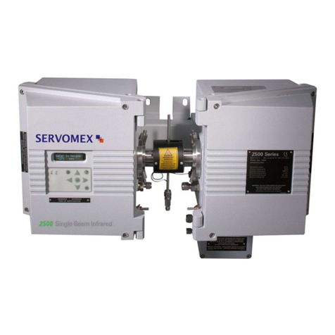
Servomex SERVOTOUGH SpectraExact 2500 Instruction manual

