Servomex NanoTrace DF-760E User manual

NanoTrace Dual
Moisture/Oxygen Analyzer
DF-760E
Instruction Manual

Copyright 2016 by Servomex Corporation
No part of this publication may be reproduced, stored in a retrieval system or transmitted in
any form, or by any means including electronic, mechanical, photocopying, recording or
otherwise without prior written permission of Servomex Corporation.
NanoTrace Moisture Analyzeris a trademark of Servomex Corporation. VCRis a
registered trademark of the Cajon Company.
DF-760E Operator Manual
Manual Version 082416

Your NanoTrace Moisture Analyzer has been designed, manufactured and is
supported under ISO-9001 controls, thus helping to insure the highest possible
standards of quality.
Every analyzer that Servomex manufactures is tested and operated on a
variety of gas concentrations to insure that it functions properly when you
receive it.
The certificate of calibration assures your analyzer has been calibrated on
gases that are traceable to NIST standards. With proper maintenance, your
analyzer should remain calibrated for years.
For a fast and successful startup, please read this manual carefully. There are
important cautions and a number of helpful hints to help you to optimize the
operation of your analyzer.
For more information or if you have questions, please do not hesitate to go to
our website at Servomex.com, or contact your local Servomex Business
Center as found on the back cover of this manual.


Read Me First…
Unpacking Procedure
Follow the procedure below to unpack your NanoTrace Dual Analyzer
1. Examine the condition of the packaging and its contents. If any damage is
apparent, immediately notify the carrier and Servomex. Do not proceed
with the installation.
2. Check the contents against the packing slip to make sure the shipment is
complete. Unattached equipment may be shipped with the analyzer in
supplemental packaging. Shortages should be reported to Servomex
immediately.
3. All NanoTrace Dual analyzers are shipped with the following:
Item
Part Number
One bottle of Electrolyte
E-Lectrolyte Gold
One bottle of Replenishment Solution
RSA
Power cord with 115 VAC connector
NOTE: No power cord is supplied with 220 VAC units
211531
USB Memory Stick, Flash Drive (SONY USM512J)
211169
VCR Filter Gasket
210432
Aspirator
210566
Zero Gas Purifier
210592
Instruction Manual
211591
4. Open the analyzer door, remove any shipping materials and verify that
nothing has come loose during transit.
5. Locate the purifier packed separately and follow the instructions on page
129 for proper installation.
6. The analyzer is set at the factory to operate on 110 VAC or 220 VAC.
Examine the voltage indicator on the rear panel to verify that the voltage is
set as ordered.
7. Save the original container in the event you may need to ship the analyzer
to another location or back to the factory (see Shipping in the Service
section). Note that shipping regulations require that the purifier be
removed from the analyzer and packaged separately as it is considered
hazardous material.

Installation and Maintenance
The NanoTrace Dual Analyzer provides years of accurate and dependable
service if it is set up, operated and maintained properly. It is essential to make
a careful and complete installation as outlined in the Installation and Start Up
section of this manual. It is assumed that NanoTrace Dual Analyzer users are
familiar with the techniques and precautions associated with Ultra-High Purity
(UHP) gas, its plumbing, and devices such as UHP regulators and gas
purifiers, and that the analyzer is used as designed and intended.
Unlike much UHP analytical equipment, NanoTrace Dual Analyzer does not
require constant maintenance. However the maintenance intervals for zero and
span calibrations, as well as addition of Replenishment Solution to the oxygen
sensor and purifier maintenance, must be determined and followed carefully.
Thank You
Thank you for selecting the NanoTrace Dual Analyzer. Servomex designs,
manufactures, exhaustively tests, and supports every analyzer under the
tightest quality controls. You should expect every Servomex analyzer to arrive
in perfect working order and, with good maintenance, provide years of
trouble-free service. Please call your nearest Servomex Business Center if you
need assistance.

Table of Contents DF-760E 3
1 Table of Contents
1Table of Contents.....................................................................3
1.1 Table of Figures...........................................................................................................6
2Cautions....................................................................................9
2.1 Symbols and Explanations...........................................................................................9
2.2 Important Warnings ...................................................................................................10
3Specifications.........................................................................17
3.1 Oxygen.......................................................................................................................17
3.2 Moisture.....................................................................................................................17
3.3 General.......................................................................................................................17
4Installation, Start Up and Shut Down...................................21
4.1 Analyzer Installation..................................................................................................22
4.1.1 General Warnings.........................................................................................22
4.1.2 Carrying the Analyzer ..................................................................................22
4.1.3 Locating and Mounting the Analyzer...........................................................22
4.1.4 Add Electrolyte to the Oxygen Sensor .........................................................23
4.1.5 Vacuum Source ............................................................................................23
4.1.6 Pneumatic Pressure Line Connection...........................................................25
4.1.7 Sample Gas Connections..............................................................................25
4.1.8 Electrical Connections..................................................................................26
4.1.9 Hydrogen Service Safety System .................................................................27
4.2 Analyzer Start Up ......................................................................................................28
4.2.1 Gas Delivery System....................................................................................29
4.2.2 Gas Pressure and Flow Settings....................................................................29
4.2.3 Moisture .......................................................................................................30
4.2.4 Oxygen .........................................................................................................31
4.2.5 Backflow Prevention System .......................................................................31
4.2.6 Purifier Installation.......................................................................................32
4.2.7 Download System Data................................................................................32
4.3 Analyzer Shut Down Or Disconnection.....................................................................32
5Options ...................................................................................35
5.1 Key Lock ...................................................................................................................35
5.2 Operating Voltage......................................................................................................35
5.3 Serial Communications..............................................................................................35
5.4 Analog Voltage Output..............................................................................................35
5.5 Hydrogen Service Safety System...............................................................................35
5.6 Vacuum Pump............................................................................................................35
5.6.1 Installation of the Vacuum Pump.................................................................36
5.6.2 Moisture Sample Gas Outlet Connection to Vacuum Pump ........................38
5.6.3 Electrical Connections..................................................................................38
6Connecting to External Devices...........................................41
6.1 Serial Communication Port –J5 ................................................................................41
6.2 Analog Signal Outputs –J4, J10................................................................................42
6.3 4-20 mA Outputs –J4, J10 ........................................................................................42
6.4 Relay Ports –J2, J3, J8, J9.........................................................................................43
7User Interface.........................................................................45
7.1 Data Display Screen...................................................................................................45

4 DF-760E Table of Contents
7.2 Keypad ......................................................................................................................46
7.3 Menu Structure..........................................................................................................46
7.4 Main Menu................................................................................................................46
7.5 Moisture Menu..........................................................................................................47
7.5.1 Moisture Controls Menu..............................................................................47
7.5.2 Moisture Calibrate Menu.............................................................................49
7.5.3 Moisture Data History Routine....................................................................55
7.5.4 Moisture Data Downloader Routine ............................................................57
7.5.5 View Moisture Logs Menu..........................................................................59
7.5.6 Moisture Alarm Setup Menu .......................................................................61
7.5.7 Moisture Analog Output Setup Routine.......................................................65
7.5.8 Moisture Graph Setup..................................................................................66
7.5.9 Moisture Diagnostics Menu.........................................................................67
7.6 Oxygen Menu............................................................................................................71
7.6.1 Oxygen Controls Menu................................................................................72
7.6.2 Oxygen Calibrate Menu...............................................................................74
7.6.3 Maintenance................................................................................................. 86
7.6.4 View Oxygen Data History..........................................................................87
7.6.5 Oxygen Data Download Routine.................................................................88
7.6.6 View Oxygen Logs ......................................................................................91
7.6.7 Oxygen Alarm SetUp...................................................................................93
7.6.8 Oxygen Analog Output Setup......................................................................97
7.6.9 Oxygen Graph Setup Screen........................................................................98
7.6.10 Oxygen Diagnostics Menu.......................................................................99
7.7 System Menu...........................................................................................................101
7.7.1 Isolate Analyzer.........................................................................................102
7.7.2 Restore Sample Gas Flow..........................................................................103
7.7.3 GSF Setup..................................................................................................103
7.7.4 Gas Delivery..............................................................................................106
7.7.5 Adjust Contrast ..........................................................................................108
7.7.6 Power Up Default ......................................................................................109
7.7.7 Test Relays.................................................................................................110
7.7.8 Test Analog Outputs..................................................................................111
7.7.9 Date/Time ..................................................................................................113
7.7.10 Communications....................................................................................114
7.7.11 Download System Data .........................................................................114
7.7.12 System Info............................................................................................116
8Sample Gas Preparation and Delivery............................... 119
8.1 Introduction.............................................................................................................119
8.2 Sample Flow Rate and Pressure ..............................................................................119
8.2.1 Moisture.....................................................................................................119
8.2.2 Oxygen.......................................................................................................119
8.3 Flow Rate Effects on Sensor Performance..............................................................120
8.3.1 Moisture.....................................................................................................120
8.3.2 Oxygen.......................................................................................................120
8.3.3 Checking for Plumbing Leaks using Flow Rate Effects ............................120
8.4 Sample Gas Scale Factor.........................................................................................121
8.4.2 Background Gas Effects on Indicated Flow Rate ......................................121
8.4.3 Pressure Effects on Oxygen Sensor Performance......................................122
8.4.4 Sample Outlet Backpressure Effects..........................................................122
8.4.5 Flammable Sample Gas .............................................................................122
8.4.6 Sample Gas Temperature...........................................................................122
8.4.7 Protecting the Analyzer from Process Upsets............................................123
9Service.................................................................................. 125
9.1 Return Material Authorization number ...................................................................125
9.2 Cautions Related To Maintenance...........................................................................125

Table of Contents DF-760E 5
9.3 Maintenance.............................................................................................................125
9.3.1 Oxygen Calibration ....................................................................................125
9.3.2 Storage Conditions .....................................................................................126
9.3.3 Oxygen Sensor Maintenance......................................................................127
9.3.4 Procedure for Adding Replenishment Solution to the Oxygen Sensor.......127
9.3.5 Moisture Cell Maintenance ........................................................................128
9.3.6 Vacuum Pump Maintenance.......................................................................128
9.3.7 Gas Purifier Maintenance...........................................................................128
9.3.8 Fuse Replacement.......................................................................................131
9.3.9 Power Cord Replacement...........................................................................132
9.4 Replaceable Parts List..............................................................................................133
9.5 Troubleshooting Guide for the NanoTrace Dual Analyzer......................................135
10 Theory of Operation.............................................................141
10.1 The Oxygen Measurement .....................................................................................141
10.1.1 The Oxygen Sensor ................................................................................141
10.1.2 The Oxygen Electrolyte Conditioning System.......................................141
10.2 The Moisture Measurement....................................................................................142
10.2.1 Moisture and the IR Spectrum................................................................142
10.2.2 Absorption Spectroscopy........................................................................143
11 Safety....................................................................................145
11.1 General Warnings...................................................................................................145
11.2 Material Safety Data Sheet (MSDS) for Electrolyte Solution................................147
11.3 Material Safety Data Sheet (MSDS) for Replenishment Solution..........................153
11.4 Material Safety Data Sheet (MSDS) for Gas Purifier ............................................156
12 Warranty ...............................................................................163
13 Index .....................................................................................165
14 Appendix A –User Menu Screens......................................168
14.1 Moisture Menus......................................................................................................168
14.2 Oxygen Menus .......................................................................................................169
14.3 System Menus ........................................................................................................171
15 Appendix B –Hydrogen Service Safety System ...............173
15.1 Instrument ..............................................................................................................173
15.2 Vacuum Pump........................................................................................................173
15.3 Installation..............................................................................................................173
15.4 Operation................................................................................................................174

6 DF-760E Table of Contents
1.1 Table of Figures
Figure 1: Overall View....................................................................................................................................20
Figure 2: Major Internal Components ............................................................................................................. 21
Figure 3: Aspirator Installation........................................................................................................................ 24
Figure 4: Rear Panel Gas Connections and Controls....................................................................................... 26
Figure 5: AC Power Input................................................................................................................................ 27
Figure 6: Data Display Screen......................................................................................................................... 28
Figure 7: Block Diagram of Gas Flow Path .................................................................................................... 33
Figure 8: Vacuum Pump Assembly................................................................................................................. 36
Figure 9: Vacuum Pump Mount Dimensions ..................................................................................................37
Figure 10: Vacuum Pump Dimensions............................................................................................................ 37
Figure 11: Vacuum Pump Power Connections and Controls .......................................................................... 38
Figure 12: Block Diagram of Gas Flow Path with Optional Vacuum Pump................................................... 39
Figure 13: Rear Panel Electrical Connectors................................................................................................... 41
Figure 14: Data Display Screen....................................................................................................................... 45
Figure 15: Keypad...........................................................................................................................................46
Figure 16: Main Menu..................................................................................................................................... 46
Figure 17: Moisture SubMenu......................................................................................................................... 47
Figure 18: Moisture Controls SubMenu .......................................................................................................... 47
Figure 19: Isolate Sensor Warning ..................................................................................................................48
Figure 20: Moisture Gas Valve Control .......................................................................................................... 49
Figure 21: Moisture Calibrate SubMenu ......................................................................................................... 49
Figure 22: Moisture Check/Adjust Zero Screen.............................................................................................. 50
Figure 23: Moisture User Zero Offset Screen.................................................................................................. 51
Figure 24: Moisture Set Zero Gas Valves Screen............................................................................................ 51
Figure 25: Moisture Manual Zero Screen........................................................................................................ 52
Figure 26: Moisture AutoZero Screen............................................................................................................. 53
Figure 27: Moisture AutoZero Setup Screen................................................................................................... 54
Figure 28: Moisture Data History.................................................................................................................... 55
Figure 29: Moisture Data History Screen........................................................................................................ 56
Figure 30: Install Media .................................................................................................................................. 56
Figure 31: Example of Data Download ........................................................................................................... 56
Figure 32: Moisture Data Downloader............................................................................................................57
Figure 33: Moisture Data Downloader Screen ................................................................................................ 57
Figure 34: View Location Screen.................................................................................................................... 58
Figure 35: Keyboard Display........................................................................................................................... 58
Figure 36: Delete Selection ............................................................................................................................. 59
Figure 37: Moisture View Logs SubMenu ...................................................................................................... 59
Figure 38: Moisture Zero Log Screen.............................................................................................................. 60
Figure 39: System Error Log Screen ............................................................................................................... 60
Figure 40: Pump Capacity Test Log................................................................................................................61
Figure 41: Moisture Alarm Setup SubMenu.................................................................................................... 61
Figure 42: Moisture Alarm Setup Screen ........................................................................................................ 63
Figure 43: Moisture Temperature Alarm Setup............................................................................................... 63
Figure 44: Moisture Pressure Range Alarm Setup .......................................................................................... 64
Figure 45: Moisture System Alarm Setup .......................................................................................................64
Figure 46: Moisture Analog Output Setup SubMenu ...................................................................................... 65
Figure 47: Moisture Analog Output Setup Screen........................................................................................... 66
Figure 48: Moisture Graph Setup SubMenu.................................................................................................... 66
Figure 49: Moisture Graph Setup Screen ........................................................................................................ 66
Figure 50: Diagnostics SubMenu .................................................................................................................... 67
Figure 51: Moisture Active Zero Setup Screen ............................................................................................... 67
Figure 52: System Monitor.............................................................................................................................. 68
Figure 53: Purge Start...................................................................................................................................... 69
Figure 54: Purifier Purge Time Line................................................................................................................ 69
Figure 55: Purge Cancel .................................................................................................................................. 70
Figure 56: Pump Capacity Test ....................................................................................................................... 70

Table of Contents DF-760E 7
Figure 57: Pump Pressure Failure ....................................................................................................................70
Figure 58: Pump Capacity Test Log.................................................................................................................71
Figure 59: Oxygen SubMenu ...........................................................................................................................71
Figure 60: Oxygen Controls Menu...................................................................................................................72
Figure 61: Oxygen Sensor Gas Valve Control Screen .....................................................................................73
Figure 62: Oxygen Sensor On/Off Control Screen ..........................................................................................73
Figure 63: Oxygen Calibrate Menu..................................................................................................................74
Figure 64: Check/Adjust Zero Screen..............................................................................................................74
Figure 65: Oxygen Manual Zero......................................................................................................................75
Figure 66: Oxygen Auto Zero Screen ..............................................................................................................76
Figure 67: Oxygen AutoZero Setup Screen .....................................................................................................77
Figure 68: Oxygen GSF Screen .......................................................................................................................79
Figure 69: Check Adjust Oxygen Span............................................................................................................80
Figure 70: Oxygen Manual Span .....................................................................................................................80
Figure 71: Oxygen AutoSpan Check................................................................................................................81
Figure 72: Oxygen AutoSpan Recal.................................................................................................................82
Figure 73: Oxygen AutoSpan SetUp Screen....................................................................................................82
Figure 74: Oxygen Signal Filter Control Screen..............................................................................................83
Figure 75: Oxygen Sensor Data Screen - Automatic .......................................................................................84
Figure 76: Install New Oxygen Sensor Calibration Data .................................................................................84
Figure 77: Oxygen Sensor Data Screen - Manual............................................................................................85
Figure 78: Oxygen Maintenance Menu............................................................................................................86
Figure 79: Replenish Sol’n Reminder Setup Screen ........................................................................................86
Figure 80: Oxygen Data History Menu............................................................................................................87
Figure 81: Oxygen Data History Screen ..........................................................................................................87
Figure 82: Install Media...................................................................................................................................88
Figure 83 Oxygen Data Downloader Menu .....................................................................................................88
Figure 84: Oxygen Data Downloader Screen...................................................................................................89
Figure 85: View Location Screen.....................................................................................................................89
Figure 86: Keyboard Display...........................................................................................................................90
Figure 87: Delete Selection..............................................................................................................................90
Figure 88: View Oxygen Logs Menu...............................................................................................................91
Figure 89: Oxygen Zero Log............................................................................................................................91
Figure 90: Oxygen Span Log ...........................................................................................................................92
Figure 91: Oxygen Replenishment Sol’n Addition Log...................................................................................92
Figure 92: Oxygen OverRange Log .................................................................................................................92
Figure 93: Oxygen Over Temperature Log......................................................................................................93
Figure 94: Oxygen Alarm SetUp Menu ...........................................................................................................93
Figure 95:Oxygen Alarm SetUp Screen...........................................................................................................95
Figure 96: Oxygen Temperature Alarm SetUp Screen ....................................................................................95
Figure 97: Oxygen Flow Alarm SetUp Screen.................................................................................................96
Figure 98: Oxygen Electrolyte Alarm SetUp Screen .......................................................................................96
Figure 99: Oxygen Sensor-Off Alarm SetUp Screen.......................................................................................97
Figure 100: Oxygen Analog Output Setup Menu.............................................................................................97
Figure 101: Output SetUp Screen ....................................................................................................................98
Figure 102: Oxygen Graph Setup Menu ..........................................................................................................98
Figure 103: Oxygen Graph SetUp Screen........................................................................................................99
Figure 104: Oxygen Diagnostics Menu............................................................................................................99
Figure 105: Oxygen Sensor Diagnostics Screen ..............................................................................................99
Figure 106: Oxygen Sensor Temperature Compensation Screen...................................................................100
Figure 107: Active Zero Setup Screen ...........................................................................................................100
Figure 108: System Menus.............................................................................................................................102
Figure 109: Isolate Analyzer..........................................................................................................................102
Figure 110: Isolate Analyzer Warning...........................................................................................................103
Figure 111: Restore Sample Gas Flow...........................................................................................................103
Figure 112: GSF Setup...................................................................................................................................104
Figure 113: GSF Setup Screen.......................................................................................................................104
Figure 114: Moisture GSF Pressure Setting...................................................................................................104

8 DF-760E Table of Contents
Figure 115: Purifier Warning......................................................................................................................... 105
Figure 116: Fan Failure Alarm ...................................................................................................................... 105
Figure 117: Gas Delivery............................................................................................................................... 106
Figure 118: Gas Delivery System Status ....................................................................................................... 106
Figure 119: Back Flow Prevention Warning ................................................................................................. 107
Figure 120: Re-established flow delay .......................................................................................................... 107
Figure 121: Adjust Contrast........................................................................................................................... 108
Figure 122: Adjust Display Contrast Screen ................................................................................................. 108
Figure 123: Power Up Default....................................................................................................................... 109
Figure 124: Power Up Default Screen........................................................................................................... 109
Figure 125: Test Relays Menu....................................................................................................................... 110
Figure 126: Test Moisture Relays.................................................................................................................. 110
Figure 127: Test Oxygen Relay..................................................................................................................... 111
Figure 128: Test Analog Outputs Menu ........................................................................................................111
Figure 129: Test Moisture Analog Output..................................................................................................... 112
Figure 130: Test Oxygen Analog Output ......................................................................................................112
Figure 131: Date/Time...................................................................................................................................113
Figure 132: Date/Time Setup Screen............................................................................................................. 113
Figure 133: Communications ........................................................................................................................ 114
Figure 134: Communications Setup Screen................................................................................................... 114
Figure 135: Download System Data.............................................................................................................. 115
Figure 136:Insert Media ................................................................................................................................ 115
Figure 137: Media Warning........................................................................................................................... 115
Figure 138: Download Time Line ................................................................................................................. 116
Figure 139: System Info ................................................................................................................................ 116
Figure 140: System Info Screen .................................................................................................................... 117
Figure 141: Firmware Upgrade ..................................................................................................................... 117
Figure 142: Gas Purifier Installation ............................................................................................................. 131
Figure 143: Schematic of NanoTrace Dual Oxygen Sensor..........................................................................141
Figure 144: Schematic of Moisture Cell........................................................................................................ 142
Figure 145: Hydrogen Service Safety System............................................................................................... 177
Figure 146: Pump Purge Option.................................................................................................................... 178

Cautions DF-760E 9
2 Cautions
2.1 Symbols and Explanations
The following symbols are used on the analyzer labels and throughout this manual.
CAUTION CONSULT MANUAL - ATTENTION CONSULTER LE MANUEL
This symbol alerts the user to the presence of hazardous conditions
that may be dangerous to individuals or equipment. To maintain
safety consult the manual when this symbol is marked on a label,
and read sections of the manual marked with this symbol.
Ce symbole informe l'utilisateur de la présence de conditions
dangereuses qui peuvent être dommageables aux personnes ou à
l'équipement. Pour assurer la sécurité, consulter le manuel lorsque
ce symbole apparaît sur l'étiquette et lire les articles du manuel
affichant ce symbole.
NOTE - REMARQUE
This symbol alerts the user to the presence of important operations
and/or maintenance information.
Ce symbole attire l'attention de l'utilisateur sur des renseignements
concernant des opérations importantes et / ou la maintenance.
CAUSTIC LIQUID - CAUSTIQUE LIQUIDE
This symbol alerts the user to the presence of caustic liquid. Refer
to the MSDS, in the Safety section of the manual, for handling
instructions.
Ce symbole informe l'utilisateur de la présence de liquide
caustique. Consulter la fiche signalétique dans la section Sécurité
du manuel pour obtenir des directives sur la manipulation.
ELECTRICAL SHOCK HAZARD - RISQUE DE CHOC ÉLECTRIQUE
This symbol alerts the user to the presence of AC voltage that is
dangerous to individuals.
Ce symbole informe l'utilisateur de la présence d'un courant
alternatif qui peut être dangereux pour les personnes.

10 DF-760E Cautions
2.2 Important Warnings
CAUTION: READ THE MANUAL
ATTENTION: LIRE LE MANUEL
Do not setup or operate this analyzer without a complete understanding
of the instructions in this manual. This analyzer must be operated in a
manner consistent with its intended use and as specified in this manual.
Servomex cannot be responsible for direct or consequential damages
that result from installing or operating the analyzer in a manner not
described in this manual.
Ne pas installer ou utiliser cet analyseur sans une compréhension
complète des instructions de ce manuel. Cet analyseur doit être utilisé
de manière conforme à l'usage prévu et tel que stipulé dans ce manuel.
Servomex ne peut pas être tenu responsable des dommages directs ou
indirects résultant de l'installation ou du fonctionnement de l'analyseur
si ceux-ci sont réalisés d'une manière qui n'est pas décrite dans ce
manuel.
CAUTION: HAZARDOUS AC
ATTENTION : TENSION DANGEREUSE
Hazardous AC voltages are present within this instrument. Do not
remove the top or left side covers - no user serviceable parts are located
under the covers. Do not connect this analyzer to AC power until all
signal cables and plumbing have been connected. Disconnect the
analyzer from AC power before installing or removing external
connections, the sensor, the electronics, or when charging or draining
electrolyte. Disconnect the analyzer from AC power before moving the
analyzer.
Un courant alternatif dangereux circule dans cet appareil. Ne pas
enlever le couvercle supérieur ou celui de gauche. Aucune pièce
pouvant être réparée par l'utilisateur ne se trouve sous ces couvercles.
Ne pas brancher cet analyseur dans une prise de courant avant que tous
les câbles d'interconnexion et les tuyaux n'aient été branchés.
Débrancher l'analyseur du courant avant d'installer ou de retirer les
connexions externes, le capteur, les pièces électroniques, ou lors du
chargement ou de la vidange de l'électrolyte. Débrancher l'analyseur de
la prise de courant avant de déplacer l'analyseur.

Cautions DF-760E 11
CAUTION: POWER CORD SAFETY
ATTENTION : SÉCURITÉ DU CORDON D’ALIMENTATION
The power cord provides the protective earth connection. Ensure that the
power cord is plugged into a properly grounded outlet that conforms to
national and local electrical codes. Avoid damaging the power cord. Do
not bend it excessively, step on it, or place heavy objects on it. A damaged
cord can be a shock or fire hazard. Never use a power cord if it is
damaged. Do not use a power cord with inadequate specifications (less
than 120 VAC, 10 Amps) or without a protective earth wire.
Le cordon d'alimentation assure la mise à la terre. S'assurer que le
cordon d'alimentation est branché dans une prise ayant une mise à la
terre conforme aux normes électriques nationales et locales. Éviter
d'endommager le cordon d'alimentation. Ne pas le plier excessivement,
marcher dessus ou placer des objets lourds sur lui. Un cordon
endommagé peut entraîner un risque d'électrocution ou d'incendie. Ne
jamais utiliser un cordon d'alimentation endommagé. Ne pas utiliser un
cordon d'alimentation dont les spécifications sont inappropriées (moins de
120 V ca, 10 ampères) ou sans fil de mise à la terre de protection.
CAUTION: 220 VAC POWER CORD
ATTENTION : LE CORDON D'ALIMENTATION DE 220 V CA
A 220 VAC power cord is not supplied with the analyzer. The customer
supplied 220 VAC power cord should be rated for 250 VAC, 10 Amps and
equipped with an IEC 60320 C13 connector for connecting to the
analyzer. This power cord provides the protective ground for the analyzer
so it must have a protective earth wire. Ensure that the power cord is
plugged into a properly grounded outlet. The power cord should have the
appropriate safety agency approvals for your location.
Un cordon d'alimentation de 220 V ca n'est pas fourni avec l'analyseur.
Le cordon d'alimentation de 220 V ca fourni par le client devrait avoir les
spécifications de 250 V ca, 10 ampères et être muni d'un connecteur
IEC60320 C13 pour le branchement à l'analyseur. Ce cordon
d'alimentation assure la mise à la terre pour protéger l'analyseur, il doit
donc comporter un fil de mise à la terre de protection. S'assurer que le
cordon d'alimentation est branché dans une prise comportant une mise à
la terre. Le cordon d'alimentation doit être conforme aux normes de
l'organisme de sécurité de l'endroit où il est utilisé.

12 DF-760E Cautions
CAUTION: CHECK AC OPERATING VOLTAGE
ATTENTION : VÉRIFICATION DE LA TENSION CA
The analyzer has been factory set to operate on either 110 or 220 VAC.
Check the voltage setting marked near the AC inlet. The analyzer may be
damaged if operated on a different voltage than marked. Changing the
operating voltage requires the analyzer to be returned to the factory.
L'analyseur a été réglé en usine pour fonctionner sur un courant ca de
110 ou 220 V. Vérifiez la tension indiquée sur l'appareil à l'entrée du
courant. L'analyseur peut être endommagé s'il fonctionne sur une tension
différente que celle indiquée. Pour modifier la tension utilisée, il faut
retourner l'analyseur à l'usine.
CAUTION: USE PROPER LIFTING, CARRYING AND MOUNTING
ATTENTION : MÉTHODES DE LEVAGE, DE TRANSPORT ET DE
MONTAGE APPROPRIÉES
The weight of this analyzer is greater than 30 kg. Proper methods of
lifting and carrying can help to protect against injury. The instrument
should be lifted and carried by two individuals. Make sure that your
balance is centered and your feet are properly spaced a shoulder width
apart when lifting the instrument. Bend at the knees and make sure your
back is straight. Grip the instrument with your fingers and palms and do
not lift unless your back is straight. Lift up with your legs, not your back.
Carry the instrument close to your body. Lower the instrument by bending
your knees. Keep your back straight.
The DF-760 is designed to be rack mounted. Ensure that the rack slides,
or support rails, are rated to support a 30 kg analyzer. Use screws in all
four front panel rack mount locations.
Cet analyseur pèse plus de 30 kg. Des méthodes appropriées de levage et
de transport peuvent vous aider à vous protéger contre les blessures.
L'appareil doit être soulevé et transporté par deux personnes. Lorsque
vous soulevez l'appareil, s'assurer que votre centre d'équilibre est bien
positionné et que vos pieds sont correctement espacés d'une distance
équivalente à la largeur entre vos épaules. Plier les genoux et s'assurer
que votre dos est droit. Saisir l'instrument avec vos doigts et votre paume
et ne lever que si votre dos est droit. Soulever avec les jambes, pas le dos.
Transporter l'appareil en le gardant près de votre corps. Abaisser
l'appareil en pliant les genoux. Garder le dos droit.
Le DF-760 est conçu pour être monté sur un support. Vérifier que les
coulisses ou les rails du support peuvent supporter un analyseur de 30 kg.
Utiliser des vis dans les quatre emplacements du panneau avant du
support.

Cautions DF-760E 13
CAUTION: FOR INDOOR USE, ONLY
ATTENTION : UTILISATION À L'INTÉRIEUR SEULEMENT
The DF-760 is for indoor use only. It should not be located in an area
where it will be subjected to particulate, condensed moisture, caustic
atmosphere, temperature extremes, or operation outside of any limits
listed in section 3, Specifications.
Le DF-760 ne s'utilise qu'à l'intérieur. Il ne doit pas être placé dans un
endroit où il peut être soumis à de la matière particulaire, à de l'eau de
condensation, à un milieu caustique, à des températures extrêmes ou à un
fonctionnement dépassant les limites énumérées à l'article 3
Spécifications.
CAUTION: CAUSTIC ELECTROLYTE
ATTENTION : ÉLECTROLYTE CAUSTIQUE
The electrolyte is a caustic solution. Review the Material Safety Data
Sheet (MSDS), located in the Safety section of this manual, before
handling the electrolyte solution.
The oxygen sensor is shipped dry and must be charged with electrolyte
before turning on the analyzer.
L'électrolyte est une solution caustique. Consulter la fiche signalétique
(MSDS), qui se trouve à la section Sécurité de ce manuel, avant de
manipuler la solution d'électrolyte.
Le capteur d'oxygène est livré sec et doit être rechargé avec de
l'électrolyte avant d'allumer l'analyseur.
CAUTION: DO NOT SHIP WITH ELECTROLYTE
ATTENTION : NE PAS TRANSPORTER AVEC DE L'ÉLECTROLYTE
DO NOT SHIP THE ANALYZER WITH ELECTROLYTE IN THE SENSOR
–THOROUGHLY DRAIN AND RINSE THE OXYGEN SENSOR BEFORE
SHIPPING.
NE PAS TRANSPORTER L'ANALYSEUR SI DE L'ÉLECTROLYTE SE
TROUVE DANS LE CAPTEUR. BIEN VIDANGER ET RINCER LE
CAPTEUR D'OXYGÈNE AVANT LE TRANSPORT.

14 DF-760E Cautions
CAUTION: OXYGEN SENSOR USE WITH PURE OXYGEN
ATTENTION : UTILISATION DU CAPTEUR D'OXYGÈNE AVEC
DE L’OXYGÈNE PUR
The DF-760 should not be used with pure oxygen. The oxygen sensor can
be permanently damaged by operation with a pure oxygen sample gas.
Le DF-760 ne doit pas être utilisé avec de l'oxygène pur. Le capteur
d'oxygène peut être endommagé de façon permanente s'il est utilisé avec
un échantillon gazeux d'oxygène pur.
CAUTION: INERT, TOXIC AND COMBUSTIBLE GASES
ATTENTION : GAZ INERTES, TOXIQUES ET COMBUSTIBLES
The DF-760, DF-750 and DF-745 analyzers have been designed for use with
inert, non-toxic, non-combustible sample gases only, such as nitrogen, helium
or argon. The DF-760, DF-750 or DF-745 may be used with the combustible
gas hydrogen if the analyzer has been factory ordered with the Hydrogen
Service Safety System option. The DF-750 and DF-745 may be used with the
reactive gas pure oxygen. The DF-740 is intended for use with the toxic gas
ammonia. The DF-730 is intended for use with the toxic gas HCl. The DF-
745SG approved gas list is ever expanding, but it includes: N2, O2, H2, He, Ar,
CO2, CO, SF6, Ne, Kr, Xe and N2O. Check your order paperwork to
determine whether your analyzer is intended for use with a toxic or
combustible gas. For toxic and combustible gases, observe the following
special installation and operation precautions:
1) Be sure to know the sample gas composition and the safe handling
requirements for that gas composition.
2) Install a shutoff valve on the sample gas inlet so that gas can be turned
off in an emergency.
3) Check all external plumbing connections for tightness before
pressurizing the sample system.
4) Vent the analyzer outlet into the appropriate facility vent system --
away from personnel (for toxic gases) and away from sources of
ignition (for combustible gases).
5) Turn off the sample gas before disconnecting the analyzer.
6) For many toxic gases a breathing air safety monitor can be purchased
(from a safety products distributor) that will notify the user if an unsafe
amount of the toxic gas is detected.
Servomex cannot be responsible for direct or consequential damages that result
from using the analyzer with these gases.

Cautions DF-760E 15
Les analyseurs DF-760, DF-750 et DF-745 peuvent uniquement être
utilisés avec des échantillons gazeux inertes, non toxiques et non
combustibles, comme l'azote, l'hélium ou l'argon. Le DF-760, DF-750 ou
DF-745 peuvent être utilisés avec de l'hydrogène gazeux combustible si
l'analyseur a été commandé à l'usine avec l'option Système de sécurité
pour utilisation avec hydrogène. Le DF-750 et DF-745 peuvent être
utilisés avec de l'oxygène gazeux pur réactif. Le DF-740 est prévu pour
être utilisé avec le gaz toxique ammoniac. Le DF- 730 est prévu pour être
utilisé avec le gaz toxique HCl. D'autres gaz s'ajouteront à la liste de gaz
approuvés pour le DF- 745SG, mais celle-ci comprend : N2 , O2 , H2 ,
He, Ar, CO2, CO, SF6, Ne, Kr, Xe et le N2O. Vérifier la documentation
de votre commande pour déterminer si votre analyseur est conçu pour
être utilisé avec un gaz toxique ou combustible. Pour les gaz toxiques et
combustibles, respecter les précautions d'installation et de
fonctionnement particulières suivantes :
1) S'assurer de connaître la composition de l'échantillon gazeux et
les exigences pour manipuler en toute sécurité cette composition
gazeuse.
2) Installer une soupape d'arrêt à l'entrée de l'échantillon gazeux afin
de pouvoir stopper l'entrée de gaz en cas d'urgence.
3) Vérifier si tous les branchements de plomberie externes sont
étanches avant de pressuriser le système de l'échantillon.
4) Acheminer la sortie de l'analyseur dans le système de ventilation
approprié, éloignée du personnel (pour les gaz toxiques) et
éloignée des sources d'ignition (pour les gaz combustibles).
5) Stopper l'échantillon gazeux avant de débrancher l'analyseur.
6) Pour de nombreux gaz toxiques un appareil de contrôle de la
sécurité de l'air respirable peut être acheté (chez un distributeur
de produits de sécurité) afin d'informer l'utilisateur si une quantité
dangereuse de gaz toxique est détectée.
Servomex ne peut pas être tenu responsable des dommages directs ou
indirects résultant de l'utilisation de l'analyseur avec ces gaz.

16 DF-760E Cautions
CAUTION: OXYGEN SENSOR OVERPRESSURE
ATTENTION : SURPRESSION DU CAPTEUR D'OXYGÈNE
Over-pressurizing the oxygen sensor can result in permanent damage to
the sensor. Limit the backpressure to the analyzer to ±1 psig (±0.07
barg).
Be sure the downstream isolation valve (if so equipped) is open before gas
flow is started.
Sur-pressuriser le capteur d'oxygène peut causer des dommages
permanents au capteur. Limiter la contre-pression à l'analyseur à ± 0,07
barg.
S'assurer que la soupape d'isolement en aval (si installée) est ouverte
avant de libérer le débit de gaz.
CAUTION: TRIPPING HAZARD
ATTENTION : RISQUE DE TRÉBUCHEMENT
Route the power cord and plumbing so that they cannot be stepped on or
tripped over.
Acheminer le cordon d'alimentation et la tuyauterie de manière à ce qu'on
ne puisse pas les piétiner ou trébucher dessus.
EMI DISCLAIMER
This Analyzer generates and uses small amounts of radio frequency
energy. There is no guarantee that interference to radio or television
signals will not occur in a particular installation. If interference is
experienced, turn-off the analyzer. If the interference disappears, try one
or more of the following methods to correct the problem:
Reorient the receiving antenna.
Move the instrument with respect to the receiver.
Place the analyzer and receiver on different AC circuits.
Table of contents
Other Servomex Analytical Instrument manuals
Servomex
Servomex 2700 User manual
Servomex
Servomex SERVOPRO k2001 User manual

Servomex
Servomex 700B User manual
Servomex
Servomex SERVOTOUGH SpectraExact 2500 Instruction manual
Servomex
Servomex xendos 1800 Series User manual
Servomex
Servomex SERVOPRO 4900 User manual
Servomex
Servomex DF-150E User manual
Servomex
Servomex DF-310E User manual
Servomex
Servomex SERVOPRO Chroma User manual
Popular Analytical Instrument manuals by other brands

Storz
Storz 112 Series instruction manual

Dostmann Electronic
Dostmann Electronic LM 50 Operating instruction
HEIDENHAIN
HEIDENHAIN TS 640 Mounting instructions
VOLTCRAFT
VOLTCRAFT 10 27 36 operating instructions
Lenntech
Lenntech Testomat 2000 operating instructions
Vivax Metrotech
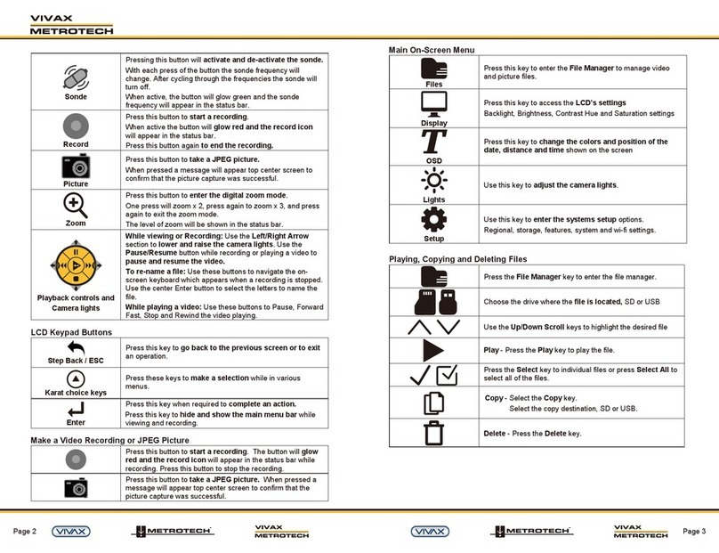
Vivax Metrotech vCamMX quick guide
