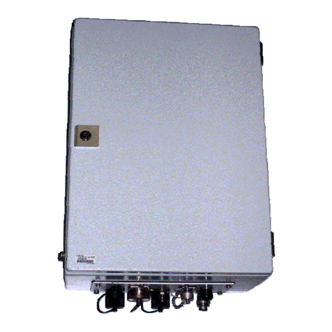
Servomex SERVOTOUGH SpectraExact 2500 Instruction manual

Part Number: 02500003E
Revision: 0
Language: UK English
SERVOTOUGH SpectraExact 2500
QUICK START MANUAL

Servomex 2500 Quick Start Manual
2 2500 Series - Configuration and Operation 02500/003E/0

Servomex 2500 Quick Start Manual
2500 Series - Configuration and Operation 02500/003E/0 3

Servomex 2500 Quick Start Manual
4 2500 Series - Configuration and Operation 02500/003E/0

Servomex 2500 Quick Start Manual
2500 Series - Configuration and Operation 02500/003E/0 5
1INTRODUCTION ........................................................................................................6
1.1 Warnings, Cautions and Notes................................................................................ 6
1.2 About this manual ................................................................................................... 6
1.3 Introduction to the user interface ............................................................................. 8
2INITIAL CONFIGURATION.........................................................................................9
2.1 Power up procedure................................................................................................ 9
2.2 General access to analyser functions...................................................................... 9
2.3 Setting passwords................................................................................................. 10
2.4 Setting time and date ............................................................................................ 11
3MAIN CONFIGURATION..........................................................................................12
3.1 Alarms................................................................................................................... 12
3.2 Allocation of relays ................................................................................................ 13
3.3 Analogue outputs .................................................................................................. 15
3.4 Defining and selecting measurement display screen............................................. 16
3.5 Communication Options ........................................................................................ 17
3.6 Communication Setup ........................................................................................... 18
3.7 RS232................................................................................................................... 18
3.8 MODBUS ASCII .................................................................................................... 20
3.9 MODBUS RTU ...................................................................................................... 20
3.10 ETHERNET........................................................................................................... 20
3.11 Functions .............................................................................................................. 21
3.12 Associate .............................................................................................................. 23
4CALIBRATION..........................................................................................................24
4.1 Introduction to calibration ...................................................................................... 24
4.2 Setting low and high calibration tolerances............................................................ 24
4.3 Manual calibration and checking ........................................................................... 25
4.4 Auto calibration and autocheck setup.................................................................... 26
4.5 Calibration when learnt cross interference is enabled............................................ 29
5VIEWING CONFIGURATION AND HISTORY FILES................................................ 30
5.1 Displaying ‘current’ alarms and faults .................................................................... 30
5.2 Displaying alarm settings ...................................................................................... 31
5.3 Displaying output configuration ............................................................................. 31
5.4 Displaying analyser histories ................................................................................. 32
5.5 Displaying analyser identity and diagnostics ......................................................... 33

Servomex 2500 Quick Start Manual
6 2500 Series - Configuration and Operation 02500/003E/0
1 INTRODUCTION
1.1 Warnings, Cautions and Notes
This publication includes WARNINGS, CAUTIONS and NOTE which provide
information relating to the following:
WARNINGS
Hazards which could result in personal injury or death.
CAUTIONS
Hazards which could result in equipment or property damage.
NOTES
Alert the user to pertinent facts and conditions.
1.2 About this manual
This manual covers software configuration and operation for the 2500, 2520 and 2550
range of analysers. Further copies of this manual may be ordered (part number
02500/003E).
Addresses for technical assistance and spares are given on the back cover.
An installation manual is supplied with the analyser which includes the technical
specification, routine maintenance and spares information.
A service manual is available for use by qualified personnel.
Some variants may be supplied with a certification manual.KEY TO FIGURES

Servomex 2500 Quick Start Manual
2500 Series - Configuration and Operation 02500/003E/0 7
KEY TO FIGURES
Figure A Analyser Front View
1. 16 Character 2 line VF Display
2. Hard key to select Measurement Display
3. Hard key to select Menu Display
4. Hard key to exit to the previous menu level
5. Fault warning LED
6. Alarm warning LED
7. Hard key to enter data or accept highlighted option within Menu
8. Up/Down/Left/Right Cursor keys to select Menu options and increase/decrease
numerical values
Figure B Analyser Menu Map
Figure C Auto calibration Examples Schematic
1. Autozero
2. Autozero and Span

Servomex 2500 Quick Start Manual
8 2500 Series - Configuration and Operation 02500/003E/0
1.3 Introduction to the user interface
See Figure A.
The keypad and display used on the 2500 series analysers have been designed to be
easy to operate and have a minimum number of keys. There are only 4 single-function
(‘hard’) keys: MEASURE; MENU; ENTER; EXIT. There are also 4 cursor (directional)
keys: Up; Down; Left; Right; these are arrow-head shapes. All keys require only a
modest pressure to operate them, and give tactile feedback.
Information is displayed on a 2-line, 16-character vacuum fluorescent display which
ensures good visibility under all conditions. Items on the display which require user-
selection are highlighted, i.e. appear flashing.
Also fitted to the keypad are red warning LEDs, one for ‘FAULT’ and one for ‘ALARM’.
These are normally only illuminated when a fault or a concentration alarm is being
signalled.
The 2500 series is controlled by the user via a ‘menu-driven’ interface; in other words,
at each level of operation the user is offered a selection, or menu, of items on the
display and he/she selects the appropriate one by highlighting it with the cursor keys
and then pressing the ENTER key. Where required, data is also entered by using the
cursor keys to increase/decrease values displayed.
Certain operations require the use of a password. There are two passwords, an
operator password and a supervisor password. These are factory set to 2000, but may
be changed if required (see Section 2.3).
Under normal operating conditions, the actual measurement result is continuously
displayed. This measurement display is the ‘default’ display. To perform any user
operations on the 2500, the user must first obtain the top-level menu display by
pressing the MENU key.
NOTE
During any operations within the menu, the fundamental measurement of the sample is
still being made by the 2500 and all relevant outputs, alarms and diagnostics remain
fully active and functioning.
To return to the (measurement) default display at any time and from any part of the
2500 user menu, simply press the MEASURE key.
NOTE
The display will also revert automatically to measurement if no key is pressed for one
minute.

Servomex 2500 Quick Start Manual
2500 Series - Configuration and Operation 02500/003E/0 9
2 INITIAL CONFIGURATION
2.1 Power up procedure
WARNING
Ensure that the instrument variant is properly installed before proceeding.
Confirm that all electrical and plumbing connections have been correctly made as
described in the installation manual.
Follow the Power up procedure as detailed in the installation manual.
The normal measurement display will then appear and the 2500 will be operational.
NOTE
•The measurement will not be valid at this point since process sample is not yet
flowing.
•If a heated cell is fitted, it will not yet be up to temperature and the intermittent
‘warming-up’ message will be displayed. Depending on set point and/or
environment, this may take several hours to reach temperature and for the
message to cease.
•The 2500 chopper box assembly will take up to 2 hours to reach specified
temperature and the ‘warming-up’ message will also be displayed until this is
accomplished.
While the analyser is warming up, the software configuration to suit the user's particular
requirements may now be accomplished. Proceed to Section 3: Configuration. Note
that during the ‘warming-up’ period, all outputs and alarms are live and fully
operational. All diagnostics are also operational, EXCEPT cell temperature and
chopper box temperature. These last two diagnostics only become operational once
the temperature set points have been reached or after 2 hours (for chopper box) or 10
hours (for cell) have elapsed from power up.
WARNING
Check for no leaks of sample at full operating pressure and temperature before
proceeding. This is especially important for toxic/flammable samples.
At this point, process sample may be turned on and allowed to flow through the 2500
sampling system.
Where the 3rd (sample/inert) solenoid valve is in use (see installation manual), the inert
medium will automatically be supplied to the analyser until the cell reaches correct
temperature.
2.2 General access to analyser functions
It is recommended that the user refers to the menu map (see Figure B) and locates the
function required. Then, using the keypad and display, follow the route as mapped. It

Servomex 2500 Quick Start Manual
10 2500 Series - Configuration and Operation 02500/003E/0
will often be necessary to enter the password.
NOTE
The factory-default password for the 2500 series is ‘2000’ - this must be entered.
Alternatively, if a keyswitch has been fitted this should now be closed. Failure to close
the keyswitch is interpreted as an invalid password, and this should prompt the user to
operate the keyswitch at this point.
NOTE
The ‘up arrow’ (↑) appears at the lower right of the display. This arrow is used
throughout the 2500 software to indicate that more information, or further items for
selection, are available and can be viewed by pressing the ▲ key. A ‘down arrow’ (↓)
means further information in the ▼ direction, and a ‘double headed’ arrow (↕) indicates
more information in either direction.
2.3 Setting passwords
NOTE
If the keyswitch facility is to be used, ignore this section.
Several sections of the 2500 menu are password-protected against unauthorised
changes by a 2-level password system. A lower-level OPERATOR password protects
basic calibration functions, and a high-level SUPERVISOR password protects the
essential configuration functions. The factory default password is ‘2000’ in both cases.
At this stage, new passwords may be selected.
NOTE
•Be sure to record the chosen passwords in a safe place.
•Three consecutive failed attempts at entering a password will cause a fault to be
signalled.
•The numbers can be scrolled round completely using the cursor keys, and the
decimal point (.) and minus sign (-) are included in the character set.

Servomex 2500 Quick Start Manual
2500 Series - Configuration and Operation 02500/003E/0 11
Go via MENU/SET UP/UTILITY/UTILITY 1 to NEW PASS - Press ENTER
At display screen Operation
SUPERVISOR
OPERATOR
Select required password and press ‘ENTER’
NEW SUPERVISOR
PASS 00 0 0
Use the cursor keys to set the new password,
then press ‘ENTER’
NEW PASS IS NNNN
ACCEPT YES/NO
To confirm new password, press ‘ENTER’
SUPERVISOR
OPERATOR
Select required password and press ‘ENTER’, or
press ‘EXIT’ to finish
2.4 Setting time and date
The 2500 is equipped with a real-time clock and this is capacitor-backed to retain the
time setting for up to 2 days without power. At this stage, it should be set to the correct
local time and date, and the preferred day/month format, in order that all future-timed
operations and historical logs reflect correct local times.
Go via MENU/SET UP/UTILITY/UTILITY 1 to CLOCK - Press ENTER
At display screen
Operation
TIME = 16:15
DATE = 07/03/00
This display will change after 4 seconds to:
CHANGE DATE/TIME
YES/NO Select ‘YES’ or ‘NO’ and press ‘ENTER’
SET CLOCK
SET YEAR 0 0 0 0
Use the cursor keys to set the correct value, then
press ‘ENTER’
SET MONTH 0 0
As above
SET DAY 0 0
As above
SET HOUR 0 0
As above
SET MINUTE 0 0 As above
SELECT FORMAT
DDMMYY/MMDDYY Select format required, then press ‘ENTER’
NOTE
Illegal times/dates outside the range of the clock are not accepted.

Servomex 2500 Quick Start Manual
12 2500 Series - Configuration and Operation 02500/003E/0
3 MAIN CONFIGURATION
3.1 Alarms
There are 4 concentration alarms for each measured component on the 2500 series,
and these are called ‘AL1’, ‘AL2’, ‘AL3’ and ‘AL4’. These must now be set up to suit the
measurement and control needs of the particular installation. Factory default settings
are 70%, 80%, 90% and 100% fsd respectively, and HIGH activation.
Each enabled alarm has four parameters which need to be set up:
i) FREEZE to prevent alarms during calibration, or FOLLOW so that alarms may be
activated by calibration gases.
ii) HIGH concentration alarm or LOW concentration alarm.
iii) The concentration LEVEL at which the alarm is to occur.
iv) The HYSTERESIS (dead band) of the alarm; this may be used to avoid ‘chatter’
if the typical sample concentration is close to the alarm level.
Go via MENU/SET UP to SET ALARM - Press ENTER
At display screen Operation
SELECT COMPONENT
CO2vpm f
(if more than 1
component)
select required component using cursor keys, then press
‘ENTER’
[Measurement]
SELECT AL 1/2/3/4
select required alarm using cursor keys, then press ‘ENTER’
[Measurement] AL1
ENABLE / DISABLE
select required state, then press ‘ENTER’
[Measurement] AL1
FREEZE / FOLLOW
select required state, then press ‘ENTER’
[Measurement] AL1
HIGH / LOW ALARM select required state, then press ‘ENTER’
[Measurement] AL1
LEVEL = 00000 [units] select required value, then press ‘ENTER’
[Measurement] AL1
HYST = 0.0% FSD
select required value, then press ‘ENTER’
[Measurement]
SELECT AL1/2/3/4
select next required alarm using cursor keys, then press
‘ENTER’, or press ‘EXIT’ to set up another component

Servomex 2500 Quick Start Manual
2500 Series - Configuration and Operation 02500/003E/0 13
3.2 Allocation of relays
Each standard 2500 series analyser has 3 relay outputs, which can now be assigned to
various functions. These relay outputs are given software identity numbers which relate
physically to the particular PCB from which they are provided. The hardware locations
and terminal strip identifiers are given in the installation manual.
Each relay output may be assigned to any combination of the following functions:
i) Any of the concentration alarms for any of the measured components, in any
combination.
ii) Calibration in Progress.
iii) Fault.
Any existing relay allocation may be edited or cleared. When cleared, the relays will
remain non-functional.
NOTES
•The Calibration in Progress function is active whenever a Manual Calibration or
Check, or an Auto calibration or Autocheck routine, is in progress.
•The Fault alarm is active whenever any Fault condition (i.e. parameter out of
tolerance) is detected, except for cell or chopper box temperature during warmup.
•Serious Faults (Shutdown/Measurement withdrawn) will also drive all analogue
outputs HIGH (or LOW, depending on user setting).
•Factory default settings are:
- All concentration alarms
- Calibration in Progress
- Faults

Servomex 2500 Quick Start Manual
14 2500 Series - Configuration and Operation 02500/003E/0
Go via MENU/SET UP/ASSIGN to RELAYS - Press ENTER
At display screen
Operation
SELECT RELAY
1.3 ASSIGNED ↑ or
1.3 UNASSIGNED ↑
Select required relay using cursor keys, then press 'ENTER'
RELAY ASSIGNMENT
1.3 EDIT / CLEAR or
1.3 ASSIGn? Y/N
Select 'EDIT' to edit allocation, or re-assign a cleared relay or
select 'CLEAR' to clear the relay, then press 'ENTER'
1.3 [Measurement] AL1
HI 10.0 % Y/N
Select 'Y' to assign this function to this relay or 'N' to clear the
function, then press 'ENTER'
1.3 [Measurement] AL2
HI 0.0 % Y/N
Select 'Y' to assign this function to this relay or 'N' to clear the
function, then press 'ENTER'
{Cycle through all the
available assignment
options, selecting with 'Y'
or 'N' as required}
Select 'Y' to assign this function to this relay or 'N' to clear the
function, then press 'ENTER'
SELECT RELAY
1.3 ASSIGNED ↑ or
1.3 UNASSIGNED ↑
Select next relay using cursor keys, then press 'ENTER'

Servomex 2500 Quick Start Manual
2500 Series - Configuration and Operation 02500/003E/0 15
3.3 Analogue outputs
Each standard 2500 series analyser has 2 analogue outputs, which can now be
assigned to the measurement being made. These analogue outputs are given software
identity numbers which relate physically to the particular PCB from which they are
provided. The hardware locations and terminal strip identifiers are given in the
installation manual for each analogue output.
Each analogue output is supplied configured as current but may be set to voltage. This
selection is made as described in the installation manual.
Each analogue output has 2 sets of parameters, one for ‘Range 1’ (normal state) and
one for ‘Range 2’ (engaged when external ‘Range 2’ contact is closed, as specified in
the installation manual).
Each analogue output can be scaled across the whole measurement range of a
component (e.g 0-100% fsd corresponds to 4-20 mA), or a smaller or larger proportion
of the calibrated range. Minimum recommended analogue output range is 5% fsd,
maximum is 200% fsd (i.e. 2x over-range). Factory default is 0-100% fsd for all outputs.
NOTE
•Above 100% fsd, linearity performance may be degraded.
•At minimum (5% fsd) output scaling, i.e. maximum expansion of output, increased
noise may require adjustment of Time Constant (see Section 3.11).
•Upper and lower limits of measurement for each output are entered in actual
concentration units. The lower limit can be non-zero, but cannot be higher than the
upper limit (i.e. reversed outputs not permitted).
The parameters which can be adjusted on the analogue outputs are:
i) LOWER and UPPER range of the output in the units of the measurement
(component).
ii) TRUE or LIVE zero. TRUE zero = 0 to 20 mA and LIVE zero = 4 to 20 mA.
iii) FREEZE to prevent alarms during calibration or FOLLOW so that alarms may be
activated by calibration gases.
Each of these parameters can also be independently set for range 2, if required.
LOWER and UPPER example:
2500 First Component Calibrated 0-20% CO2
Default analogue output range:
(4-20 mA) corresponds to (0-20% CO2)
Minimum output range:
(4-20 mA) corresponds to (0-1% CO2)
Maximum output range:
(4-20 mA) corresponds to (0-40% CO2*)
(* = approx)

Servomex 2500 Quick Start Manual
16 2500 Series - Configuration and Operation 02500/003E/0
The analogue identity (in this case ‘1.1’) appears lower left, and the current status
(ASSIGNED OR UNASSIGNED) next to it. All are initially ASSIGNED in the factory to
the measurements in logical order, one analogue per measurement.
Go via MENU/SET UP/ASSIGN to ANALOGUE - Press ENTER
At display screen
Operation
SELECT ANALOGUE
1.1 ASSIGNED ↑ OR
1.1 UNASSIGNED ↑
Select required analogue output using cursor keys, then press
‘ENTER’
ANALOGUE
ASSIGNMENT 1.3 EDIT /
CLEAR OR
1.3 ASSIGN? Y/N
Select ‘EDIT’ to edit allocation, or re-assign a cleared relay
OR select ‘CLEAR’ to clear the relay, then press ‘ENTER’
SELECT COMPONENT
CO2vpm t
(if more than 1
component)
Select component to be assigned to this analogue output
using cursor keys, then press ‘ENTER’
1.1 [Measurement] R1
L=00.0 U=20.0
Select Lower and Upper limits for the output and press
‘ENTER’
1.1 [Measurement] R1
TRUE 0 / LIVE 0
Select required state, then press ‘ENTER’
1.1 [Measurement] R1
FREEZE / FOLLOW
Select required state, then press ‘ENTER’
1.1 [Measurement] R2
L= 00.0 U=20.0
Repeat above process for range R2
SELECT ANALOGUE
1.1 ASSIGNED ↑ OR
1.1 UNASSIGNED ↑
Select another analogue output using cursor keys, then press
‘ENTER’
3.4 Defining and selecting measurement display screen
The window menu enables the user to display the measurement value and measured
component in the preferred format for the (default) measurement display.
Go via MENU/SET UP/UTILITY/UTILITY 1 to WINDOW - Press ENTER
At display screen
Operation
SELECT SCRN /
UDEF DEFINE SCRN
/ VARS
Select required function using cursor keys, then press ‘ENTER’
SELECT SCRN is used to display the required measured components on the display.
AUTOSCROLL is used on multi component analysers only, and is used to show all
measured components in a continuous circular scroll.

Servomex 2500 Quick Start Manual
2500 Series - Configuration and Operation 02500/003E/0 17
If SINGLE display is selected, the name of a chosen measured component appears on
the top line and the measurement value on the bottom line.
The SPLIT display is used on multi component analysers only, and is used to show two
measured components at a time.
UDEF is used to select the required displayed chemical name, chemical formula and
engineering unit, e.g. carbon dioxide, CO2, vpm.
DEFINE SCREEN is used on multi component analysers only, and is used to specify
the sequence order in which the measured components are displayed.
VARS is used to set the number of displayed digits (DECIMAL POINTS) appearing
after the decimal point in the measurement value. This is adjustable between values of
0 to 3.
3.5 Communication Options
A standard 2500 provides RS232 serial communications. If specified, the analyser may
be fitted with additional hardware to allow digital communications using either Modbus
over RS485 or Modbus TCP over Ethernet. If either option is fitted the RS232 output is
no longer available.
The 2500 menu system displays all communication options but for correct operation
the selection must match the analyser hardware. The following table lists the options.
Go via COMMS to SET COMMS MODE - Press ENTER
At display
screen
Operation
Analyser Option
NONE
OR
Select required
option using cursor
keys, then press
‘ENTER’
Any
RS232
OR
Standard
MODBUS
OR
ASCII
02500912 Communications Board RS485
MODBUS
OR
RTU
02500912 Communications Board RS485
ETHERNET
02500913 Communications Board Ethernet
NONE disables all digital communications.
RS232 enables the serial output and print functions. See section 3.7 for further details.
Modbus ASCII enables this protocol using the RS485 interface on the 02500912
Communication Board (if fitted).
Modbus RTU enables this protocol using the RS485 interface on the 02500912
Communication Board (if fitted).

Servomex 2500 Quick Start Manual
18 2500 Series - Configuration and Operation 02500/003E/0
Ethernet enables Modbus TCP communication using Ethernet interface on the
02500913 Communication Board (if fitted)
WARNING
Do not use an uncertified DCS, dilatator, printer or other external equipment in a
Hazardous Area.
3.6 Communication Setup
When the communication mode has been selected as described in section 3.5, it may
be configured using the SET COMMS PARMS menu. Note that this menu is only
displayed if the communication mode is not NONE.
The configuration options displayed are specific to the selected communication mode
and are described in the following sections.
3.7 RS232
The RS232 option uses the following fixed configuration.
BAUD rate: 2400
PARITY: EVEN
STOP BITS: 1
DATA BITS: 8
HANDSHAKE: HARDWARE
Any device intended for connection to the 2500 must be capable of serial RS232
communication and be configured with these settings.
Entering the RS232 menu displays further options.
SERIAL
This option configures the analyser to transmit serial data frames at user configurable
time intervals. For connection details and signal interpretation, refer to the installation
manual.
Go via MENU/COMMS/SET COMMS PARMS to SERIAL - Press ENTER
At display screen
Operation
FRAME PERIOD =
00s
Select required value using cursor keys, then press ‘ENTER’. A
zero value will disable transmission.
PRINT
The PRINT MENU is only displayed if the FRAME PERIOD under the SERIAL menu is
set to zero. It is provided to enable the user to download hard copy records of the
2500’s Identity (ID), current history logs (Alarm, Fault and calibration histories) and
complete SET-UP information. Any printer must have at least 80 column width.
Go via MENU/COMMS/SET COMMS PARMS to PRINT - Press ENTER

Servomex 2500 Quick Start Manual
2500 Series - Configuration and Operation 02500/003E/0 19
At display screen
Operation
SYSTEM SET-UP OR
IDENTITY OR
HISTORY
Select required value then press ‘ENTER’

Servomex 2500 Quick Start Manual
20 2500 Series - Configuration and Operation 02500/003E/0
3.8 MODBUS ASCII
This section details the analyser configuration that is displayed when the
communications mode is set to MODBUS ASCII. This should be adjusted as necessary
to match the requirements of the Modbus network to which the analyser is connected.
Go via MENU/COMMS to SET COMMS PARMS - Press ENTER
At display screen
Operation
MODBUS ADDRESS =
247
Select required value from 1 to 247 and press ‘ENTER’
SELECT STOP 1 / 1.5 /
2
Select required value and press ‘ENTER’
SELECT DATA BITS 8 /
7
Select required value and press ‘ENTER’
SELECT PARITY EVEN
/ ODD / NONE
Select required value and press ‘ENTER’
SELECT BAUD RATE
9K6 / 4K8 / 2K4 / 19K2 Select required value and press ‘ENTER’
3.9 MODBUS RTU
This section details the analyser configuration that is displayed when the
communications mode is set to MODBUS RTU. This should be adjusted as necessary
to match the requirements of the Modbus network to which the analyser is connected.
3.10 ETHERNET
This section details the analyser configuration that is displayed when the
communications mode is set to ETHERNET. This should be adjusted as necessary to
match the requirements of the network to which the analyser is connected.
Go via MENU/COMMS to SET COMMS PARMS - Press ENTER
At display screen
Operation
IP ADDRESS =
000.000.000.000
Select required value and press ‘ENTER’
SUBNET MASK =
000.000.000.000
Select required value and press ‘ENTER’
GATEWAY ADDRESS =
000.000.000.000
Select required value and press ‘ENTER’
Note that the SUBNET MASK value is automatically set to the appropriate default
value whenever an IP address is entered that falls into a different class. This may be
altered as required.
This manual suits for next models
1
Table of contents
Other Servomex Analytical Instrument manuals
Servomex
Servomex DF-150E User manual
Servomex
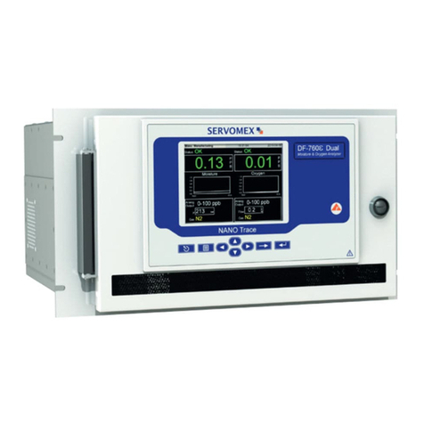
Servomex NanoTrace DF-760E User manual
Servomex
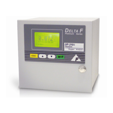
Servomex DF-310E User manual
Servomex
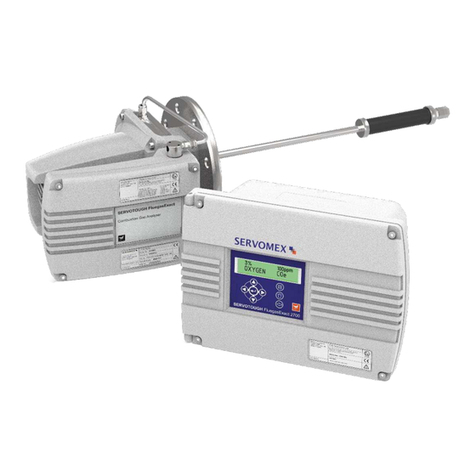
Servomex 2700 User manual
Servomex
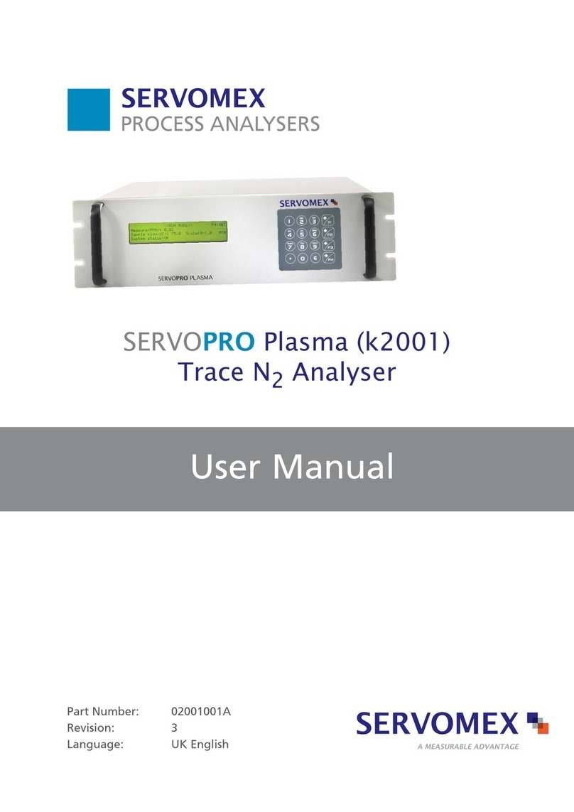
Servomex SERVOPRO k2001 User manual
Servomex
Servomex SERVOPRO Chroma User manual

Servomex
Servomex xendos 1800 Series User manual

Servomex
Servomex SERVOPRO 4900 User manual

Servomex
Servomex 700B User manual
