SEW-Eurodrive CBG22A Operating instructions

*26864967_0321*
Drive Technology \ Drive Automation \ System Integration \ Services
Addendum to the Operating
Instructions
Local Keypad
CBG22A
Local Operating Unit with Diagnostics, Manual Mode and Process
Data Interface
Edition 03/2021 26864967/EN

SEW-EURODRIVE—Driving the world

1
General information
About this documentation
Addendum to the Operating Instructions – CBG22A 3
1 General information
1.1 About this documentation
The documentation at hand is the original.
This documentation is an integral part of the product. The documentation is intended
for all employees who perform work on the product.
Make sure this documentation is accessible and legible. Ensure that persons respon-
sible for the systems and their operation as well as persons who work on the product
independently have read through the documentation carefully and understood it. If you
are unclear about any of the information in this documentation or if you require further
information, contact SEW‑EURODRIVE.
1.2 Other applicable documentation
This documentation supplements the operating instructions of the associated product.
Use this document only in connection with the operating instructions.
Always use the latest edition of the documentation and the software.
The SEW‑EURODRIVE website (www.sew‑eurodrive.com) provides a wide selection
of documents for download in various languages. If required, you can also order prin-
ted and bound copies of the documentation from SEW‑EURODRIVE.
1.3 Structure of the safety notes
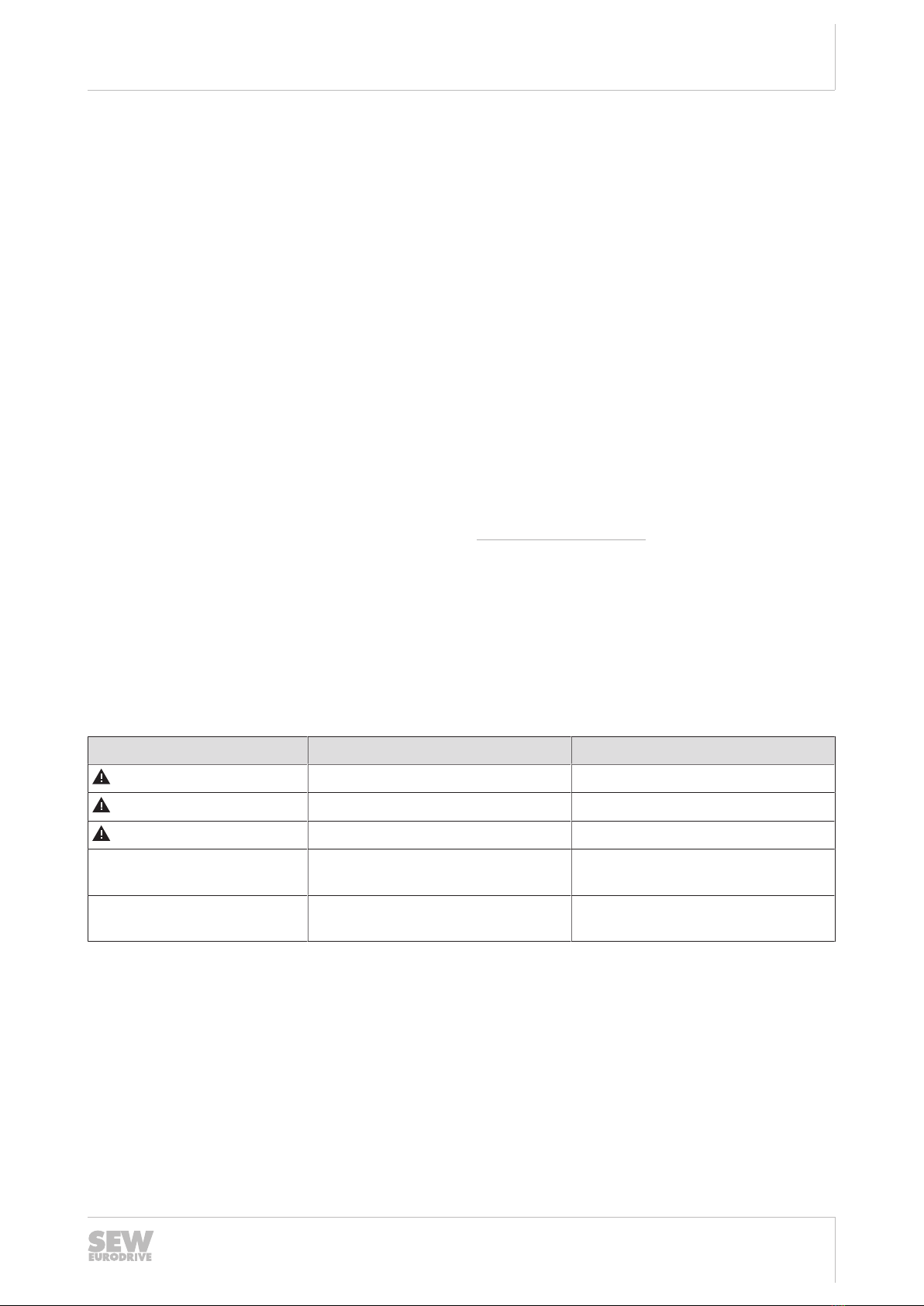
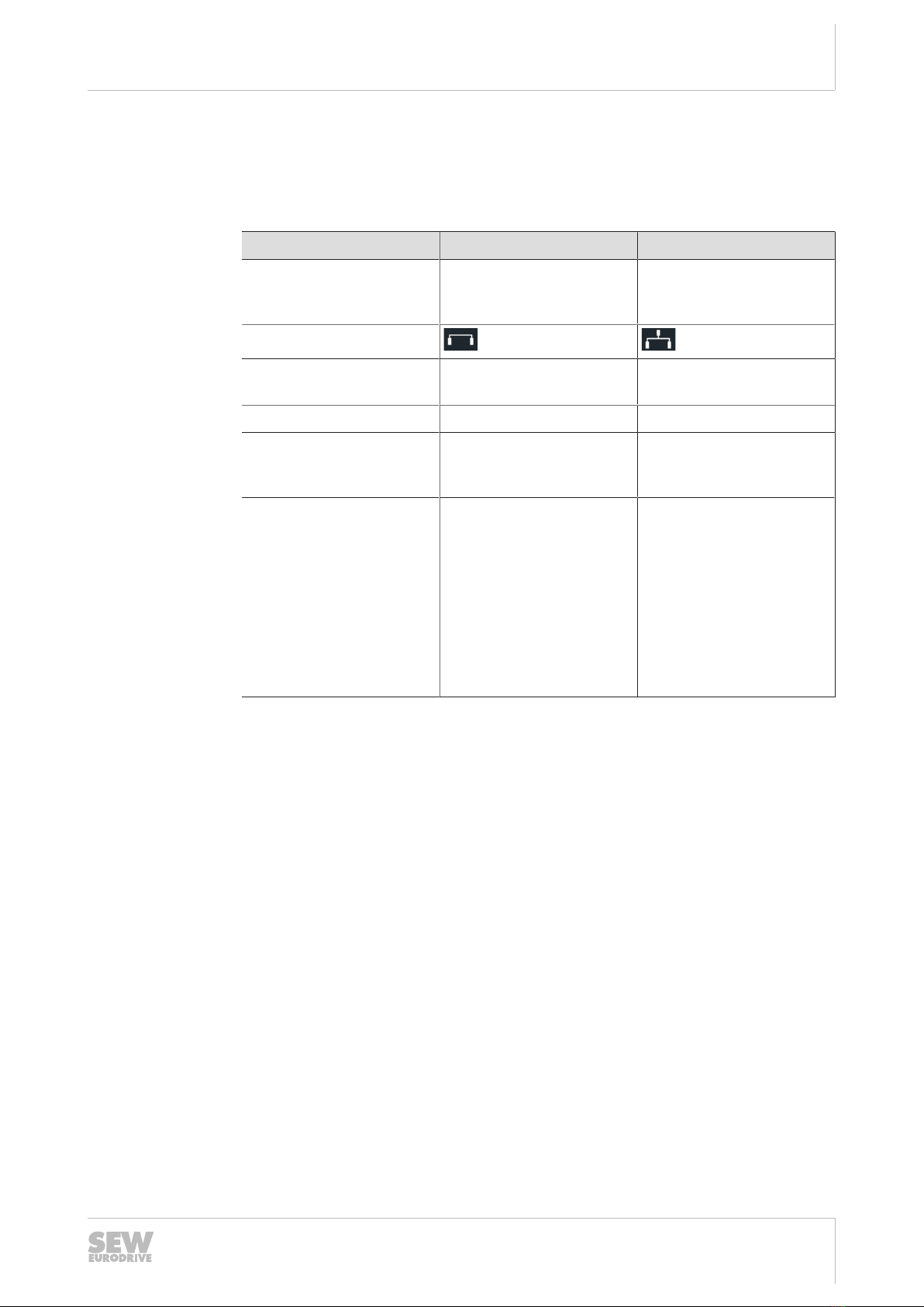
1.3.1 Meaning of signal words
The following table shows the grading and meaning of the signal words for safety
notes.
Signal word Meaning Consequences if disregarded
DANGER Imminent hazard Severe or fatal injuries
WARNING Possible dangerous situation Severe or fatal injuries
CAUTION Possible dangerous situation Minor injuries
NOTICE Possible damage to property Damage to the product or its envi-
ronment
INFORMATION Useful information or tip: Simplifies
handling of the product.
1.3.2 Structure of section-related safety notes
Section-related safety notes do not apply to a specific action but to several actions
pertaining to one subject. The hazard symbols used either indicate a general hazard
or a specific hazard.
26864967/EN – 03/2021

1General information
Decimal separator in numerical values
Addendum to the Operating Instructions – CBG22A
4
This is the formal structure of a safety note for a specific section:
SIGNAL WORD
Type and source of hazard.
Possible consequence(s) if disregarded.
• Measure(s) to prevent the hazard.
Meaning of the hazard symbols
The hazard symbols in the safety notes have the following meaning:
Hazard symbol Meaning
General hazard
1.3.3 Structure of embedded safety notes
Embedded safety notes are directly integrated into the instructions just before the de-
scription of the dangerous action.
This is the formal structure of an embedded safety note:
SIGNAL WORD! Type and source of hazard. Possible consequence(s) if disregar-
ded. Measure(s) to prevent the hazard.
1.4 Decimal separator in numerical values
In this document, a period is used to indicate the decimal separator.
Example: 30.5kg
1.5 Rights to claim under limited warranty
Read the information in this documentation. This is essential for fault-free operation
and fulfillment of any rights to claim under limited warranty. Read the documentation
before you start working with the product.
1.6 Product names and trademarks
The brands and product names in this documentation are trademarks or registered
trademarks of their respective titleholders.
1.7 Copyright notice
©2021SEW‑EURODRIVE. All rights reserved. Unauthorized reproduction, modifica-
tion, distribution or any other use of the whole or any part of this documentation is
strictly prohibited.
26864967/EN – 03/2021

Table of contents
Addendum to the Operating Instructions – CBG22A 5
Table of contents
1 General information.................................................................................................................. 3
1.1 About this documentation ...............................................................................................3
1.2 Other applicable documentation .....................................................................................3
1.3 Structure of the safety notes ...........................................................................................3
1.4 Decimal separator in numerical values ...........................................................................4
1.5 Rights to claim under limited warranty ............................................................................4
1.6 Product names and trademarks......................................................................................4
1.7 Copyright notice ..............................................................................................................4
2 Device structure ....................................................................................................................... 6
2.1 CBG22A local keypad.....................................................................................................6
2.2 Operating modes ............................................................................................................7
2.3 Representations and functions .....................................................................................10
2.4 Example nameplate of a local keypad ..........................................................................16
3 Electrical installation.............................................................................................................. 17
3.1 PC connection...............................................................................................................17
4 Startup ..................................................................................................................................... 18
4.1 Process data .................................................................................................................18
4.2 Process data configuration ...........................................................................................19
4.3 Process data description...............................................................................................21
5 Technical data and dimension sheets.................................................................................. 26
5.1 Technical data...............................................................................................................26
26864967/EN – 03/2021

2Device structure
CBG22A local keypad
Addendum to the Operating Instructions – CBG22A
6
2 Device structure
2.1 CBG22A local keypad
The following figure shows the CBG22A local keypad (front and rear):
Type: CBG22A
28277554 .0100.1000
0003461
P#:
S#:
03/20 443
[1]
[5]
[6]
[7]
[3] [4][2]
34005940491
[1] Color display
[2] Function keys (function according to bottom line on color display)
[3] USB 2.0 MiniB interface, female (PC connection)
[4] Lock
[5] D-Sub interface, 9-pin, female
[6] Nameplate
[7] Info key (for information about the selected menu)
Keys The following figure shows the required keys of the CBG22A local keypad:
[6] [7]
[3]
[4]
[5]
[1]
[2]
[1] Key 1 " "
[2] Key 2 " "
[3] Key 3 " "
[4] Key 4 " "
[5] Key 5 "OK"
[6] Key 6 "STOP"
[7] Key7 "RESET"
26864967/EN – 03/2021

2
Device structure
Operating modes
Addendum to the Operating Instructions – CBG22A 7
2.2 Operating modes
The CBG22A local keypad has 2 operating modes: direct control mode and indirect
control mode. You can switch between the two operating modes by means of process
data. The table below lists the main differences between the two operating modes.
Direct control mode Indirect control mode
Switchover via
control word1 of
indirect control mode
Bit 0 = 0 Bit 0 = 1
Symbol
Data exchange Locally between inverter
and local keypad
Via process data and
higher-level controller
Manual mode Can be activated Cannot be activated
Response to key switch The manual mode screen
opens. The drive can be
moved directly.
The monitoring screen
opens.
Monitoring Dedicated diagnostics
screen
Settings can be made via
process data
• Background color can
be set
• Free text can be output
• Keystrokes are evalu-
ated
• Background brightness
can be set
26864967/EN – 03/2021

2Device structure
Operating modes
Addendum to the Operating Instructions – CBG22A
8
2.2.1 Direct control mode
In direct control mode, the local keypad communicates directly with the inverter via the
engineering interface of the inverter. Data exchange looks as follows:
34008570507
Bit0 of control word1 of indirect control mode has the value"0". This means the local
keypad is in direct control mode, e.g. in the event of a fieldbus communication failure.
Actuating the key switch enables manual mode. The drive can be controlled directly in
manual mode if no fault is present.
All screens except for manual mode serve only for diagnostic purposes. No parame-
ters, with the exception of a fault reset, can be written to the drive but can only be
read.
26864967/EN – 03/2021

2
Device structure
Operating modes
Addendum to the Operating Instructions – CBG22A 9
2.2.2 Indirect control mode
In indirect control mode, the local keypad communicates with the inverter via a higher-
level controller (PLC). Bit 0 of control word 1 of indirect control mode has the
value"1".
With the monitoring menu open, the local keypad has the following functions in indirect
control mode:
• The local keypad sends the data entered using the keys to the higher-level control-
ler (PLC) via the process data of the inverter.
• Alphanumeric characters can be transferred via process data and displayed on the
color display for interaction purposes with the user. The background color of the
display can also be modified via process data.
• The higher-level controller can generate the inverter setpoints based on the entries
made on the local keypad, and can control the inverter using these setpoints.
The process data (PD) for the indirect control mode of the local keypad are configured
on the inverter. The inverter exchanges these process data cyclically with the local
keypad as follows:
Data exchange
PD indirect control mode
3 – 16PD
1 – 13 PO Control word inverter
1 – 14 PI Status word inverter
2 – 3 PO Indirect control mode (controller)
2 PI Indirect control mode (status)
34006686987
Actuating the key switch opens the monitoring screen.
All screens except for the monitoring screen serve only for diagnostic purposes. No
parameters, with the exception of a fault reset, can be written to the drive but can only
be read.
26864967/EN – 03/2021

2Device structure
Representations and functions
Addendum to the Operating Instructions – CBG22A
10
2.3 Representations and functions
2.3.1 Icons
The display of the local keypad shows the selectable functions in the form of icons.
Icon Meaning
Start menu
Monitoring
MOVISAFE® CS..
1 2
DIP switch
Process data
Digital inputs/outputs
Operating and energy data
Device information
Fault memory
Gateway operation
Settings
26864967/EN – 03/2021

2
Device structure
Representations and functions
Addendum to the Operating Instructions – CBG22A 11
Icon Meaning
Main menu
Manual mode
Direct control mode active
Indirect control mode active
26864967/EN – 03/2021

2Device structure
Representations and functions
Addendum to the Operating Instructions – CBG22A
12
2.3.2 Mein menu
The diagnostics screens in the main menu can be selected via tiles. Options that are
not available are dimmed.
34036803211
2.3.3 Monitoring
By default, the monitoring menu is the start screen in both operating modes. This
menu shows the current utilization of the motor and the utilization of the output stage.
The current speed in user units and an applied FCB or fault is also displayed.
34036805643
In indirect control mode, users can change the background color, display a free text,
and adjust the brightness in this menu. In addition, the keystrokes are evaluated in this
menu and passed on to the higher-level controller for processing.
26864967/EN – 03/2021

2
Device structure
Representations and functions
Addendum to the Operating Instructions – CBG22A 13
2.3.4 Manual mode
Manual mode is started solely in direct control mode by actuating the key switch. The
menu can only be exited with the key switch position ="0".
34036800779
In manual mode, the current actual speed is displayed in user units and the setpoint
speed in user units. The speed can be increased or decreased using the double arrow
keys on the local keypad. Pressing of the keys is indicated by an operating cross on
the display.
The two arrow keys right and left start the drive in the corresponding direction of rota-
tion at the set speed.
Manual mode can be enabled by 2 different key actuating modes: momentary and
latching. Pressing the second function key from the right changes between the 2
modes. The selected function also affects the manual release and application of the
brake.
• Latching function: By briefly pressing the "RUN CW" or "RUN CCW" key, the drive
starts and continues until the key is pressed again or the stop key is pressed.
• Momentary function: The drive moves only as long as the "RUN CW" or "RUN
CCW" key has been pressed (jog mode).
The brake can be released or applied manually by pressing the first function key from
the left.
26864967/EN – 03/2021

2Device structure
Representations and functions
Addendum to the Operating Instructions – CBG22A
14
2.3.5 Key switch function
The key switch is essential for using the CBG22A local keypad.
Manual mode is activated solely by the position of the key switch in direct control
mode. Activating the key switch in indirect control mode opens the monitoring screen.
With key switch position = "0" manual mode is exited immediately in direct control
mode. An enabled drive then stops based on the deceleration set in manual mode.
Present setpoints and control signals are immediately active again.
26864967/EN – 03/2021

2
Device structure
Representations and functions
Addendum to the Operating Instructions – CBG22A 15
Overview of key switch functions
The following figure shows the operating principle of the key switch in more detail.
Start
No
Yes
Yes
End
NoNo
No
Yes Yes
Key switch
actuated?
Direct
control mode active?
(Indirect control mode
control word 1
bit 0 = 0)
Monitoring
screen opens
Key switch
continues to be
active?
Last opened
menu
is
displayed
Manual mode
screen opens
Drive is directly
controlled
by CBG22A
Key switch
continues to be
active?
34036798347
26864967/EN – 03/2021

2Device structure
Example nameplate of a local keypad
Addendum to the Operating Instructions – CBG22A
16
2.4 Example nameplate of a local keypad
2.4.1 Nameplate
The following figure shows the nameplate of a CBG22A local keypad:
Type: CBG22A
28277554 .0100.1000
0003461
P#:
S#:
09/21 443
[6]
[1]
[3]
[2]
[5]
[4]
34006671115
[1] The 2D code on the nameplate indicates the part number of the local keypad.
[2] Firmware status
[3] Hardware status
[4] Unique serial number
[5] Part number and status
[6] Type designation
2.4.2 Type designation
The following table shows an example type designation of the CBG22A local keypad:
Type designation Description Part number
CBG GenerationC keypad option 28277554
22 Local keypad
AVersion
26864967/EN – 03/2021

3
Electrical installation
PC connection
Addendum to the Operating Instructions – CBG22A 17
3 Electrical installation
3.1 PC connection
The following figure shows an example of how to connect the PC to the local keypad
of MOVIMOT®flexible MMF3..:
[1]
[2]
USB
34184949515
[1] USB/MINI USBB connection cable (commercially available, high-speed type)
[2] CBG22A local keypad
26864967/EN – 03/2021

4Startup
Process data
Addendum to the Operating Instructions – CBG22A
18
4 Startup
4.1 Process data
The following process output data (PO) and process input data (PI) are available for
data exchange between the higher-level controller (PLC) and the CBG22A local
keypad:
PO Indirect control mode
Control word
Function
PO1 Control word 1 (required) Mode selection, display color, display bright-
ness, diodes
PO2 Control word 2 (required) Mode selection for transferring the character
code,
transfer of a character code
PO3 Control word 3 (optional) Optional parallel transfer of a second charac-
ter code
PE Indirect control mode
Status word
Function
PE1 Status word [0] (required) Mode, input status
PE2 Status word [1] (required) Feedback that control word2 has been trans-
ferred successfully
26864967/EN – 03/2021

4
Startup
Process data configuration
Addendum to the Operating Instructions – CBG22A 19
4.2 Process data configuration
Configure the control words and status words in the process data image of the con-
nected inverter.
4.2.1 Configuring control words
INFORMATION
Transparent mode corresponds to indirect control mode.
Configure the control words as follows:
üThe PC is connected with the local keypad.
üThe inverter has been successfully started up.
1. Start MOVISUITE®.
2. In the parameter tree of the inverter, select parameter number 4.2.24 "Transparent
mode" [1].
3. Assign the required process output data words [2] of the inverter to the control
words 1 to 3 of the transparent mode.
[2]
[2]
[2]
[1]
9007225901804299
26864967/EN – 03/2021

4Startup
Process data configuration
Addendum to the Operating Instructions – CBG22A
20
4.2.2 Configuring status words
INFORMATION
Transparent mode corresponds to indirect control mode.
Configure the status words as follows:
üThe PC is connected with the local keypad.
üThe inverter has been successfully started up.
1. Start MOVISUITE®.
2. In the parameter tree of the inverter, select parameter number 4.3.1 "PI data" [1].
3. Assign status words [0] and [1] of transparent mode to the respective process in-
put data words [2] of the inverter.
[2]
[2]
[1]
9007226995700875
26864967/EN – 03/2021
Table of contents
Other SEW-Eurodrive Keypad manuals
Popular Keypad manuals by other brands

Interlogix
Interlogix NX-182xx NetworX User reference guide

Resolution Products
Resolution Products RE152 user manual

Ramset Gate Openers
Ramset Gate Openers Heddolf Programming instructions

Russound
Russound A-K3 installation manual

Alarm Controls Corporation
Alarm Controls Corporation KP-100A manual

Manhattan
Manhattan 176354 reference guide

FBII
FBII XL STAR 4500 owner's manual

CZone
CZone 6-Way Waterproof Keypad User & installation manual

SDC
SDC EntryCheck 923P installation instructions

olympia electronics
olympia electronics JA-81F manual

Burg Wächter
Burg Wächter TSE 5111 operating instructions

Assa Abloy
Assa Abloy S series Installation & programming guide