SGM LEKTRA PTU51 User manual
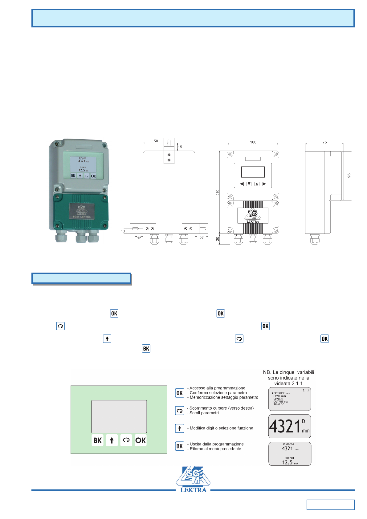
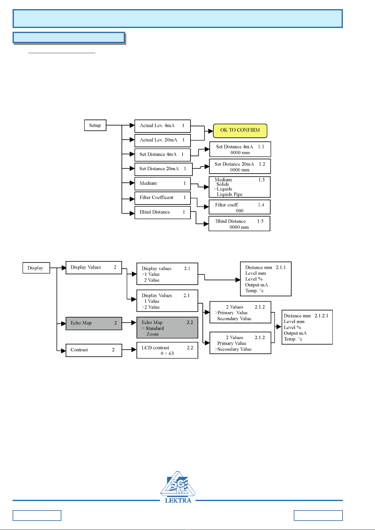
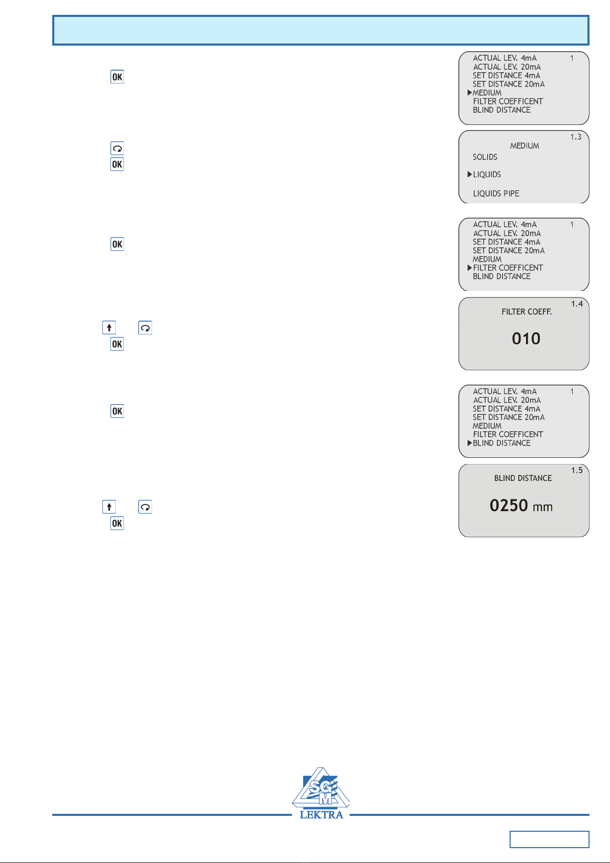
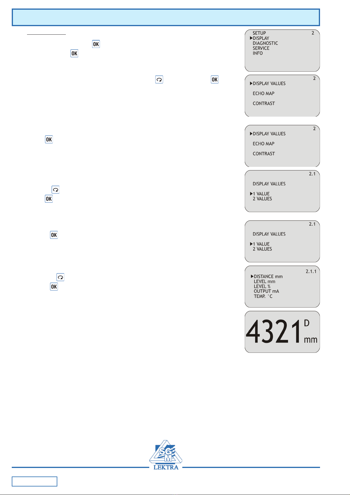
fig.3
fig.2
fig.1
applied solution for the application
Install
perpendicularly
to the surface
Do not use
with foaming
products
Avoid to install in
case of product
level distance
<0.3m from the
sensor
Important!!! close to the sensor there is a “blind zone” of
0.3m where the instrument can’t measure (see fig.3). To
reach a good and safe measurement, avoiding spurious
echoes (not reflected by the surface), take care of the
positioning of the PTU51 sensor and check that no obstacles
are interferring with the ultrasonic waves emission lobe (see
fig.2).
PTU51 Mechanical Installation
Technical Data
Housing material: PP or PVDF
Mechanical installation: 1”GAS M
Sensor protection degree: IP68
Electrical connection: IP68 or IP69K male connector
with 5/10/15/20m linking cable
Working temperature: -25° ÷ +75°C
Pressure: da 0,5 a 1,5 bar (absolute)
Power supply: 24Vdc
Power consumption: 1,5W
Analog output: 4÷20mA max 750ohm
Digital communication:MODBUS RTU
Measure range: 0.3÷6m
[In case of non perfectly reflecting surfaces, the maximu distance
value will be reduced]
Blind distance: 0,3m
Temperature compensation: digital from -30 to 80°C
Accuracy: ±0,2% (of the measured distance)
not better than ±3mm
Resolution: 1mm
Calibration: VLW601 prog. module with 4 buttons
or by MODBUS RTU
Warm-up: 30 minutes typical
LCD Display: VLW601 wall mounting module
PTU51
Ultrasonic level transmitter
825B124A

Page 2 of 16
3.1 Via MODBUS RTU
3.1.1 MODBUS RTU PC connection (fig.10)
1) RS232 or USB connector
2) PTU51
3) RS232/485 or USB/RS485 interface module
3. CONFIGURAZIONE
The PTU51 configuration and calibration can be done in two different ways:
- via MODBUS RTU by PC
- by the keyboard VLW601 module
Fig.10
2. CONNECTIONS
Table 1 shows the cable color/signal corresponding
PTU51 dimensions- dimensions
1. DIMENSIONS
Tab.1
Fig.4
nworB)V0(DNG
deRcdV42+
etihWyalpsiDADS
wolleYAm02÷4+
neerG)584SR(A
eulB)584SR(B
kniPyalpsiDV3.3+
yerGyalpsiDLCS

Page 3 of 16
3.2 Via VLW601
3.2.1 Keyboard/display module VLW601 (fig.11)
The VLW601 module can be the easy way to configure your PTU51.
The VLW601module has a large matrix LCD (Fig.12)
Also you can view the measure with:
- 2 values (small characters)
- 1 value (big characters)
The operating manual allows an easy and fast start-up through the keyboard.
Note: if VLW601 is connected, MODBUS RTU is not enable.
PTU51 Configuration
Fig.11
4. VLW601 MODULE
The VLW601 programming module has 4 buttons (Fig.12) that allows for all transmitter control and
programming operational functions:
- From “RUN” mode: press to enter “PROGRAM” mode, press to quit
- Press to move the cursor on the parameter you want to use and confirm with
- To edit numbers, press to modify the digit shown in negative, press to edit the next digit, press to
confirm and store the number. Press to quit
In the display top right there is always a number, eg. "1.2". This number is the menu or parameter index that’s
displayed
The menu structure is represented on page 4 and page 5
Fig.12

Page 4 of 16
PTU51 Programming menu structure
5. MENU STRUCTURE
5.1 Programming menu
1. SETUP – in this menù it’s possible to set the basic adjustment of the sensor
2. DISPLAY – in this menù it’s possible to setup the sensor display mode an adjust the contrast of LCD
3. DIAGNOSTIC - in this menù it’s possible to test and check the sensor, display peak values and measure status.
4. SERVICE - in this menù it’s possible to set com mode and output mode.
5. INFO - this menù show firmware revision, serial number and manufacturer information
Pag. 4 di 24

Page 5 of 16
PTU51 Programming menu structure
Pag. 5 di 24

Page 6 of 16
PTU51 - Configuration
6. CONFIGURATION
6.1 SETUP (1)
From “RUN” mode press then move the cursor on “SETUP”
and confirm with
Select the parameters by moving the cursor with , and confirm with
6.1.1 ACTUAL LEV. 4mA
Press to associate the actual measure with 4mA output value;
the following message will be displayed:
OK TO CONFIRM; press to confirm
6.1.2 ACTUAL LEV. 20mA
Press to associate the actual measure with 20mA output value;
the following message will be displayed:
OK TO CONFIRM; press to confirm
6.1.3 SET DISTANCE 4mA
Press to display the value of distance associated with 4mA output.
Use and to modify that value.
Press to confirm
6.1.4 SET DISTANCE 20mA
Press to display the value of distance associated with 20mA output.
Use and to modify that value.
Press to confirm

Page 7 of 16
PTU51 - Configuration
6.1.5 MEDIUM
Press to access the settings change.
There are 3 possible configurations:
Solids - granular solids measurement
Liquids - liquids measurement
Liquids Pipe - liquids measurement in pipe reference
Press to select the product type.
Press to confirm
6.1.6 FILTER COEFFICENT
Press to access the settings change.
input a value from 1 to 100 (10 default) to smooth the response of the sensor:
the biggest is the value, the smoothest is the response
Use and to modify that value.
Press to confirm
6.1.7 BLIND DISTANCE
Press to access the settings change.
represent the “BLIND ZONE” of the sensor. Input the desired value in order
to avoid measures near the surface of the sensor (if necessary).
The minimum value is 300mm
Use and to modify that value.
Press to confirm

Page 8 of 16
PTU51 - Configuration
6.2 DISPLAY (2)
From “RUN” mode press , then move the cursor on “DISPLAY”
and confirm with
Select the parameters by moving the cursor with , and confirm with
6.2.1 DISPLAY VALUES
Press to access the settings change.
It’s possible to select if one value with big digits or two values are shown
on the display in “RUN” mode
With the button you can select the parameter to be programmed.
Press to confirm.
6.2.1.a VALUE
Press to access the settings change.
only one value is displayed; it’s possible to choose from 5 parameters.
With the button you can select data to display.
Press to confirm.

Page 9 of 16
PTU51 - Configuration
6.2.1.b VALUES
Press to access the settings change.
Two values are displayed; it’s possible to choose which one is the primary
and which is the secondary, each with a choice of 5 parameters
With the button you can select data to display
Press to confirm.
6.2.2 ECHO MAP
NOT YET AVAILABLE.
6.2.3 CONTRAST
Press to access the settings change.
it’s possible to adjust the contrast of LCD, simply increasing or
decreasing the value of a parameter from 0 to 63 (16 default)
Use and to modify that value.
Press to confirm.

Page 10 of 16
PTU51 - Configuration
6.3 DIAGNOSTIC (3)
From “RUN” mode press , then move the cursor on “DIAGNOSTIC”
and confirm with
With the button you can select the parameter to be programmed.
Press to confirm.
6.3.1 FALSE ECHO DETECT
Press to access the "FALSE ECHO DETECT" function.
It’s necessary to imput the empty distance (distance from the instrument
to the bottom of the tank)
Use and to modify that value.
Press to confirm.
The system will automatically scan and store all echoes separating false
echoes from the real one that match the empty distance.
After this,the following message is displayed:
FALSE ECHO DETECT DONE
If something’s not corretct (e.g wrong empty distance value, obstacles
that hides the bottom) the following message is displayed
FALSE ECHO DETECT ERROR
Note: False echo detect procedure is not recommended for pipe and stand-pipe applications
6.3.2 FALSE ECHO MAP
NOT YET AVAILABLE
6.3.3 MEASURE STATUS
Press to access the “MEASURE STATUS” function.
It’s possible to display the gain of the system, with values from 0 to 255.
While displayed, the automatic gain control is not active

Page 11 of 16
PTU51 - Configuration
6.3.4 FROZEN GAIN
Press to access the “FROZEN GAIN” function.
It’s possible to fix a value of gain (from 1 to 255) and consequently
disable the automatic gain control. Once the value is 000 the automatic
gain control restarts
Use and to modify that value.
Press to confirm.
6.3.5 MAX GAIN TH
Press to access the “MAX GAIN TH” function.
it’s possible to input a value of gain that it should be not reached.
If the gain is above this value, an error occours.
Use and to modify that value.
Press to confirm.
6.3.6 PEAK VALUES
Press to access the “PEAK VALUES” function.
The system store the maximum distance and the minimum distance
measured since the power is turned ON.
It’s possible to see those values or reset the values
With the button you can select the function.
Press to confirm.
6.3.6.I DISPLAY VALUES
Press to access the “DISPLAY VALUES” function.
Displays the max. and min. distance measured from reset or power on.

Page 12 of 16
PTU51 - Configuration
6.3.6.II RESET VALUES
Pressing erase all the stored values
6.3.7 OUTPUT SIMULATION
Press to access the “OUTPUT SIMULATION” function.
It’possible to force the analog output to a desired value.
Use and to modify that value.
Press to exit
The output returns to its normal function in only in “RUN” mode.
6.3.8 AGITATORS
Press to access the “AGITATORS” function.
It’s possible to set the agitator’s impellers presence recognition.
With the setting "0000" function is disabled
Use to select the distance to be set and press 2 times to change
the value in the menu 3.7.1
In the line "Dist.ag.1 - upper" sets the distance of the sensor from the agitator
blades top.
In the line “Dist.ag.1 - lower” sets the distance of the sensor from the agitator
blades bottom.
In the line "Dist.ag.2 - upper" sets the distance of the sensor from the second
agitator blades top.
In the line “Dist.ag.2 - lower” sets the distance of the sensor from the second
agitator blades bottom.
Use and to modify that value.
Press 2 time to confirm.

Page 13 of 16
PTU51 - Configuration
6.4 SERVICE (4)
From “RUN” mode press , then move the cursor on “SERVICE”
and confirm with
Select the parameters by moving the cursor with , and confirm with
6.4.1 OUTPUT SAFE MODE
Press to access the “OUTPUT SAFE MODE” function.
It’s possible to choose a value of analog output durin condition of system’s
internal errors. “HOLD LAST VALUE” keep the output at the level corresponding
at last valid measure.”
With the button you can select the operation mode.
Press to confirm
6.4.2 COM MODE
Can assign the address UID in this submenu, for a MUDBUS RTU network.
Use and to modify that value.
Press to confirm.
6.4.3 LANGUAGE
NOT YET ACTIVE.
6.4.4 PASSWORD
NOT YET ACTIVE.
Pag. 13 di 24

Page 14 of 16
PTU51 - Quick Guide
6.5 INFO (5)
From “RUN” mode press , then move the cursor on “INFO”
and confirm with
Informations about manufacturer, firmware version and serial number
are displayed.
6.4.5 CHECK FREQUENCY
Press to access the “CHECK FREQUENCY” function.
It’s possible to check the computed emission frequency of the sensor
6.4.6 F-WINDOW
Press to access the “F-WINDOW” function.
With the enabled AGITATORS function, it’s possible to set the threshold for
acquisitions in succession that the same echo signal must reach to be
considered valid, in the agitators working area.
With the disabled AGITATORS function, F-WINDOW is the static filter
updating speed.

Page 15 of 16
PTU51 - Quick Guide
7. QUICK GUIDE
7.1 0% Calibration
For the 0% (4mA) calibration are possible 2 procedures: for self-learning (7.1.1) or by inserting the corresponding
distance (7.1.2)
7.1.1 ACTUAL LEV. 4mA
From “RUN” mode press then move the cursor on “SETUP”
and confirm with . Select the “ACTUAL LEV. 4mA” parameters by moving the
cursor with , and confirm with the following message will be displayed:
OK TO CONFIRM; press to confirm.
7.1.2 SET DISTANCE 4mA
From “RUN” mode press then move the cursor on “SETUP”
and confirm with . Select the “SET DISTANCE 4mA” parameters by moving the
cursor with , and confirm with to display the value of distance associated
with 4mA output; use and to modify that value.
Press to confirm.
7.2 100% Calibration
For the 100% (20mA) calibration are possible 2 procedures: for self-learning (7.2.1) or by inserting the corresponding
distance (7.2.2)
7.2.1 ACTUAL LEV. 20mA
From “RUN” mode press then move the cursor on “SETUP”
and confirm with . Select the “ACTUAL LEV. 20mA” parameters by moving the
cursor with , and confirm with the following message will be displayed:
OK TO CONFIRM; press to confirm.
7.2.2 SET DISTANCE 20mA
From “RUN” mode press then move the cursor on “SETUP”
and confirm with . Select the “SET DISTANCE 20mA” parameters by moving the
cursor with , and confirm with to display the value of distance associated
with 20mA output; use and to modify that value.
Press to confirm.

Documentation subject to technical change with no prior warning
PTU51 - Factory Test Certificate
In conformity to the company and check procedures I certify that the equipment:
PTU51............. Serial n. ......................
is conform to the technical requirements on Technical Data and it is made in conformity to the SGM-LEKTRA procedure
Quality Control Manager .............................................
Production and check date .............................................
PTU51 Warranty
Products supplied by SGM LEKTRA are guaranteed for a period of 12 (twelve) months from delivery date according to the
conditions specified in our sale conditions document.
SGM LEKTRA can choose to repair or replace the Product.
If the Product is repaired it will mantein the original term of guarantee, whereas if the Product is replaced it will have 12
(twelve) months of guarantee.
The warranty will be null if the Client modifies, repair or uses the Products for other purposes than the normal conditions
foreseen by instructions or Contract.
In no circumstances shall SGM LEKTRA be liable for direct, indirect or consequiential or other loss or damage whether
caused by negligence on the part of the company or its employees or otherwise howsoever arising out of defective goods
SGM LEKTRA s.r.l.
Via Papa Giovanni XXIII, 49
20090 Rodano (Milano)
tel. ++39 0295328257 r.a.
fax ++39 0295328321
e-mail: [email protected]
web: www.sgm-lektra.com
Table of contents
Other SGM LEKTRA Transmitter manuals

SGM LEKTRA
SGM LEKTRA FLOWMETER Guide

SGM LEKTRA
SGM LEKTRA RPL81 User manual

SGM LEKTRA
SGM LEKTRA RPL75 User manual

SGM LEKTRA
SGM LEKTRA METER Series Quick start guide

SGM LEKTRA
SGM LEKTRA RPL81 User manual

SGM LEKTRA
SGM LEKTRA TC26 User manual

SGM LEKTRA
SGM LEKTRA PTU50 User manual

SGM LEKTRA
SGM LEKTRA METER Guide

SGM LEKTRA
SGM LEKTRA MTU5 User manual

SGM LEKTRA
SGM LEKTRA KPT Guide