SGM LEKTRA RPL81 User manual

RPL81
80GHz Radar level transmitter
technical documentation EN Rev. of 11/04/2022

Page 2 of 40 www.sgm-lektra.com
RPL81 - contents
CONTENTS
1-WARRANTY
2-PRODUCT
3-PERFORMANCE SPECIFICATIONS
4-DIMENSIONS
5-INSTALLATION
6-ELECTRICAL CONNECTIONS
7-CONFIGURATION MODES
8-OPERATOR INTERFACE
9-QUICK SETUP
10-ADVANCED SETUP
11-FACTORY TEST AND QUALITY CERTIFICATE
page 3
page 4
page 5
page 6
page 7
page 10
page 12
page 17
page 18
page 26
page 40

Page 3 of 40
www.sgm-lektra.eu
RPL81 - warranty
Products supplied by SGM LEKTRA are guaranteed for a period of 12 (twelve) months from delivery date
according to the conditions specified in our sale conditions document.
SGM LEKTRA can choose to repair or replace the Product.
If the Product is repaired it will maintain the original term of guarantee, whereas if the Product is replaced it will have 12
(twelve) months of guarantee.
The warranty will be null if the Client modifies, repair or uses the Products for other purposes than the normal conditions
foreseen by instructions or Contract.
In no circumstances shall SGM LEKTRA be liable for direct, indirect or consequential or other loss or damage whether
caused by negligence on the part of the company or its employees or otherwise howsoever arising out of defective goods
1-WARRANTY

Page 4 of 40 www.sgm-lektra.com
RPL81 - product
2- PRODUCT
1. Skintop M16
2. Headxingbolt
3.Fixingbolt
4. Watertight connector M12
5. Sensor
6. 5m integrated cables
2.1 IDENTIFICATION
Eachmeterhasanadhesiveidenticationplateonwhichareindicatedthemetermaindata.
Thefollowingpicturedescribestheinformationontheidenticationplate.
RPL81
24Vdc
MU0081604506
2
3
1Mod.
P.S.
S.N.
1. Product code 3. Serial number2. Power supply
1
2
3
4
“1” version “3” version
5
5
6
3
5
“2” version

Page 5 of 40
www.sgm-lektra.eu
3-FEATURES
RPL81 - features
Housing/sensor material
PP
Mechanical installation
2” GAS M (Flange in PP DN80 (opt.)
Protection degree
IP67/IP68 (Sensor) - IP68 (opt.)
Electrical connection
Terminals, connector or 5m integrated cables (IP68)
Working temperature
-20 ÷ +60°C
Pressure
from 0,5 to 1,5 bar (absolute)
Power supply
24Vdc
Power consumption
5W peak; 2,5W average
Analog output
4...20mA,max750ohm
Relays output
n°2 3A 230Vac (n.o.) with a resistive load
Digital communication
MODBUS RTU
Max measure range
0.05÷10mtmaxforsolids
0.05÷20mtmaxforliquids
Incaseofnonperfectlyreectingsurfaces,themaximumdistancevaluewillbereduced
Blind distance
0,05m
Accuracy
±0,2% (of the measured distance) not better than ±3mm.
Resolution
2mm.
Calibration
Display module - MODBUS - 2 pushing buttons (only for IP67 version) / Bluetooth
LCD Display
VL620(IP67vers.)orVL621(IP68vers.)display/keyboard4buttonsmatrixLCD

Page 6 of 40 www.sgm-lektra.com
4-DIMENSIONS
RPL81 - dimensions
5.1 MECHANICAL DIMENSIONS
2" G
Ch.68
N° 2 FIXING BOLT 2"
16 Ø190
Ø18
Ø150
2" GAS
DN80 PN6 UNI 1092-1 flange in PP (Opt.)
222
Ø55,5

Page 7 of 40
www.sgm-lektra.eu
RPL81 - installation
5-INSTALLATION
5.1 MOUNTING PRECAUTIONS
5.1.1 Mounting position
- Leave a 300mm (d) minimum distance between the sensor and the tank smooth wall.
- Use a protective cover to protect the sensor from weather and direct sunlight (c).
- Do not install the sensor near the load zone (a).
- Makesurethatinthesensoremissionbeam(lobe“α”5°)therearenoobstacles(f,e)thatcanbe
intercepted as level.
g
5.1.3 Blind distance
Duringinstallationisimportanttorememberthatinthesensorproximitythereisablindzone(orBLINDDISTANCE)of
0.05m where the sensor can not measure.
Blind Distance0.05m
5.1.2 Special European directive
According to EN 302 729, paragraph 4.6.1.3, a minimum distance of 4 km from radio astronomy sites is required,
unless special authorization has been provided by the responsible national regulatory authority.
Also, at the distance between 4 km and 40 km from any radio astronomy site, the height of the LPR antenna should not
exceed15mabovetheground.
Page 8 of 40 www.sgm-lektra.com
RPL81 - installation
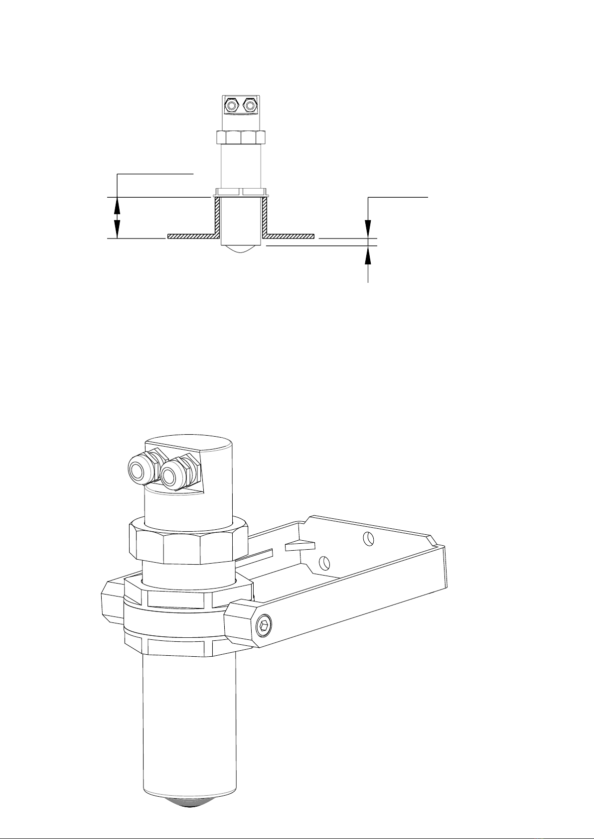
5.1.4 Installation in nozzle
In case of nozzle installation, make sure the sensor bottom protrudes at least 10mm from the bottom of the nozzle.
5.1.5 Installation with bracket (mod. 835B026Z)
By installing the RPL81 with the bracket it is possible to orient the emission lobe perpendicular to inclined surfaces
≥10mm.
Max 90mm.

Page 9 of 40
www.sgm-lektra.eu
RPL81 - installation
5.1.6 Agitators presence
ThelevelmeasurementispossiblethankstotheAuto-Tunedstatisticallter.
Shouldrarelyneedtoadjusttheltersettingbyediting2RPL81sensorprogrammingparameters:
-FILTER;thisparameterispresentintheQuickSetupmenuandintheAdvancedConguration“SETUP”menu;
increasing the parameter value, decreases the sensor sensitivity to the level measurement sudden variations.
-F-WINDOW;thisparameterispresentintheAdvancedConguration“SERVICE”menu;decreasingtheparameter
programmed value, increases the sensor immunity to false echoes.

Page 10 of 40 www.sgm-lektra.com
RPL81 - electrical connections
+24Vdc
0Vdc RL1 RL2
Power
Supply
MODBUS
4÷20mA
RL2 LED
Indicates the relay 2 status:
turner on, relay RL2 energized
ECO LED
Flashes during
Signal receiving
RL1 LED
Indicates the relay 1 status:
turned on, relay RL1 energized
MODE LED
Steady on
Flashes during transmission data
via MODBUS RTU
Micro USB-B
6-ELECTRICAL CONNECTIONS
6.1 “1” VERSION CONNECTIONS
1) Separate the engine control cables or power cables from the RPL81 connection cables
2) Open the cap by unscrewing.
3) Lead the cables into the transmitter through the glands
4) Close the cap and tighten the cable glands
6.2 “2” VERSION CONNECTIONS
BROWN
RED
YELLOW
WITHE
GREY
PINK
GREEN
BLUE
(2)
(1)
(3)
(4)
(5)
(6)
(7)
(8)
BROWN
RED
YELLOW
WITHE
GREY
PINK
GREEN
BLUE
(2)
(1)
(3)
(4)
(5)
(6)
(7)
(8)
GND DISPLAY
+3,3V DISPLAY
+ 4/20mA
SCL DISPLAY
- 4/20mA
SDA DISPLAY
A RS485 MODBUS
B RS485 MODBUS
N / 0V
L / +24V
C RL1
N.O. RL1
C RL2
N.O. RL2
N.C.
N.C.
C1
POWER - RED CABLE
C2
SIGNAL - BLACK CABLE

Page 11 of 40
www.sgm-lektra.eu
RPL81 - electrical connections
6.3 “3” VERSION CONNECTIONS
BROWN
RED
YELLOW
WITHE
GREY
PINK
GREEN
BLUE
(2)
(1)
(3)
(4)
(5)
(6)
(7)
(8)
BROWN
RED
YELLOW
WITHE
GREY
PINK
GREEN
BLUE
(2)
(1)
(3)
(4)
(5)
(6)
(7)
(8)
GND DISPLAY
+3,3V DISPLAY
+ 4/20mA
SCL DISPLAY
- 4/20mA
SDA DISPLAY
A RS485 MODBUS
B RS485 MODBUS
N / 0V
L / +24V
C RL1
N.O. RL1
C RL2
N.O. RL2
N.C.
N.C.
C1
POWER - RED CABLE
C2
SIGNAL - BLACK CABLE
6.3 HUMIDITY INFILTRATIONS
Toavoidthehumidityinltrationinsidethehousingisrecommended:
- to use a cable with a 5÷10mm outer diameter and fully tighten the M16 cable gland for electrical connections
- to fully tighten the cap
- to position the cable so that it forms a downward curve at the M16 output; in this way the condensation and/or the
rain water will tend to drip from the curve bottom
Page 12 of 40 www.sgm-lektra.com
RPL81 - electrical connections / conguration modes
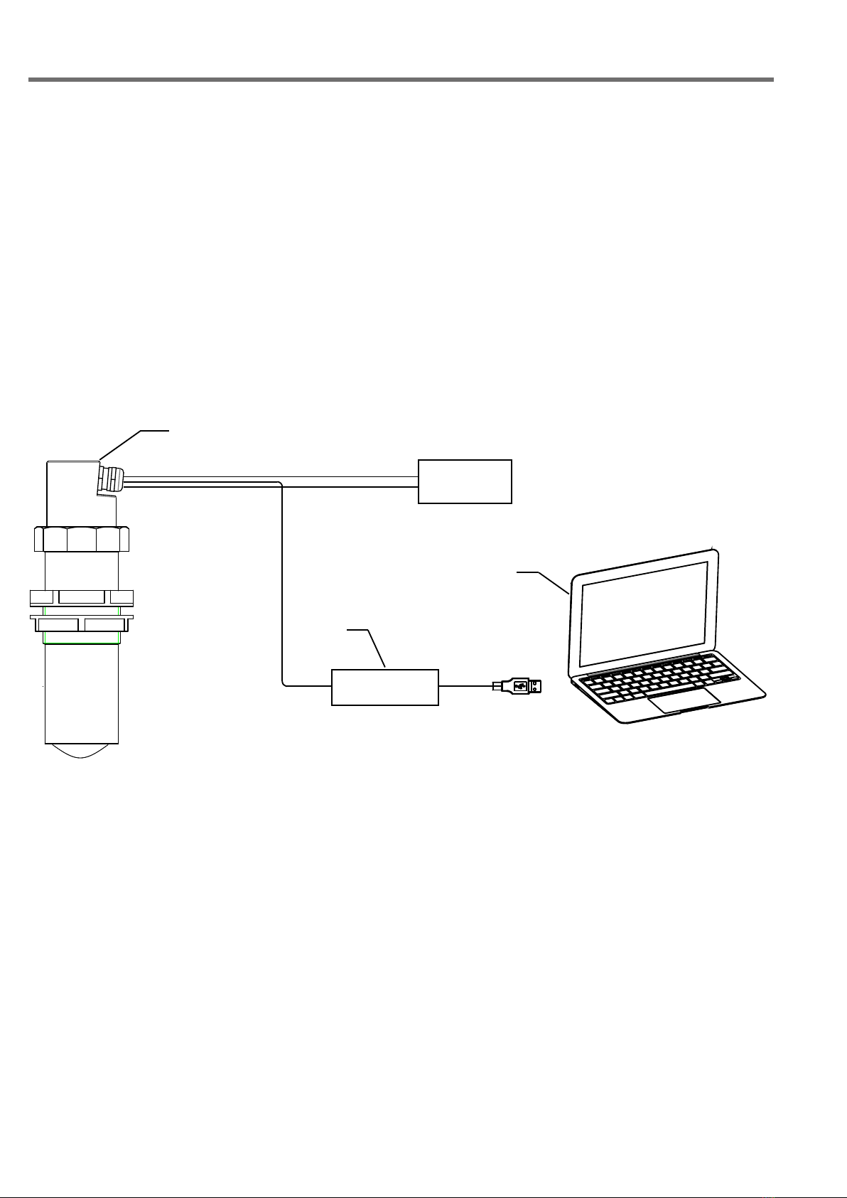
7.1 DIGITAL COMMUNICATIONS CONNECTION
7.1.1 RPL81 MODBUS RTU PC connection
1) RPL81 with MODBUS RTU communication protocol
2) USB/RS485 interface module, cod.694A004A
3) MODBUS RTU communication S/W, cod.010F105A, for RPL81 transmitter
Withthissowareispossible:
- to connect the RPL81 transmitters in MODBUS RTU network by selecting the UID address
- to read on your PC monitor all measures in reading and RPL81 operation data
-toprogramallRPL81congurationparameters
- to store the measurement readings and the operating status of RPL81
7-CONFIGURATION MODES
TheRPL81have4conguration/calibrationmodes:
-viadigitalcommunication:viaMODBUSRTU,byPC
- via 2 on board buttons
- via VL620 or VL621 programming module
- via Bluetooth with Android App
1
2
3
USB/RS485
POWER
SUPPLY

Page 13 of 40
www.sgm-lektra.eu
MODBUS REGISTERS FOR RPL81
Address
(dec)
Address
(hex)
(N°of
registers)
Type Description
0 0 1 unsigned int Distance
1 1 1 unsigned int Level
2 2 2 oat Level %
6 6 2 oat Analog output
10 A 1 unsigned int Distance 4mA
11 B 1 unsigned int Distance 20mA
12 C 1 unsigned int DAC 4mA
13 D 1 unsigned int DAC 20mA
14 E 1 unsigned int Blind distance
22 16 1 unsigned int Filter coeicent
24 18 1 unsigned int UID
37 25 1 unsigned int Delay setpoint RL1
39 27 1 unsigned int Delay setpoint RL2
42 2A 1 unsigned int Delay pump control RL1
43 2B 1
44 2C 1 unsigned int Alarm mode (MAX/MIN) RL1
45 2D 1 unsigned int Safety (NO/YES) RL1
46 2E 1 unsigned int Enable RL1
47 2F 1 unsigned int Alarm mode (MAX/MIN) RL2
48 30 1 unsigned int Safety (NO/YES) RL2
49 31 1 unsigned int Enable RL2
50 32 1 unsigned int Pump control mode RL1
51 33 1 unsigned int Enable pump control RL1
52 34 1 unsigned int Enable diagnostic alarm RL2
53 35 1 unsigned int Measurement return power
54 36 1
55 37 1 unsigned int Echo error
56 38 1
57 39 1 unsigned int Distance error
58 3A 1 unsigned int Output alarm status for analog output
59 3B 1 unsigned int Relay RL1 status
60 3C 1 unsigned int Relay RL2 status
65 41 1 unsigned int F_WINDOW value
69 45 1 unsigned int Setpoint threshold RL1 (Distance from sensor)
70 46 1 unsigned int Setpoint threshold RL2 (Distance from sensor)
71 47 1 unsigned int UPPER Setpoint pump RL1 (Distance from sensor)
72 48 1 unsigned int LOWER Setpoint pump RL1 (Distance from sensor)
73 49 1 unsigned int Modbus RS485 Parity
74 4A 1 unsigned int Modbus RS485Baudrate

Page 14 of 40 www.sgm-lektra.com
MODBUS REGISTERS FOR RPL81
Measure
unit
R W Note
mm 03h
mm 03h
% 03h
mA 03h
mm 03h 06h
mm 03h 06h
03h
03h
mm 03h 06h
03h 06h
03h 06h
s 03h 06h
s 03h 06h
s 03h 06h
03h 06h 0:MAX1:MIN
03h 06h 0:Norm_disexcited1:Norm_excited
03h 06h 0:disabled1:enabled
03h 06h 0:MAX1:MIN
03h 06h 0:Norm_disexcited1:Norm_excited
03h 06h 0:disabled1:enabled
03h 06h 0:EMPTYING1:FILLING
03h 06h 0:disabled1:enabled
03h 06h 0:disabled1:enabled
03h 0…32767
03h
03h
03h 06h 4:21.5mA6:38.5mA8:HoldLastValue
03h 0:o1:on
03h 0:o1:on
03h 06h 0:ltersdisabled
mm 03h 06h
mm 03h 06h
mm 03h 06h
mm 03h 06h
03h 06h 0:NoParity1:Even2:Odd
03h 06h 0:96001:19200
Baud rate 9600bps
8data bit
2stop bit
no parity
noHWowcontrol
Page 15 of 40
www.sgm-lektra.eu
RPL81 - conguration modes
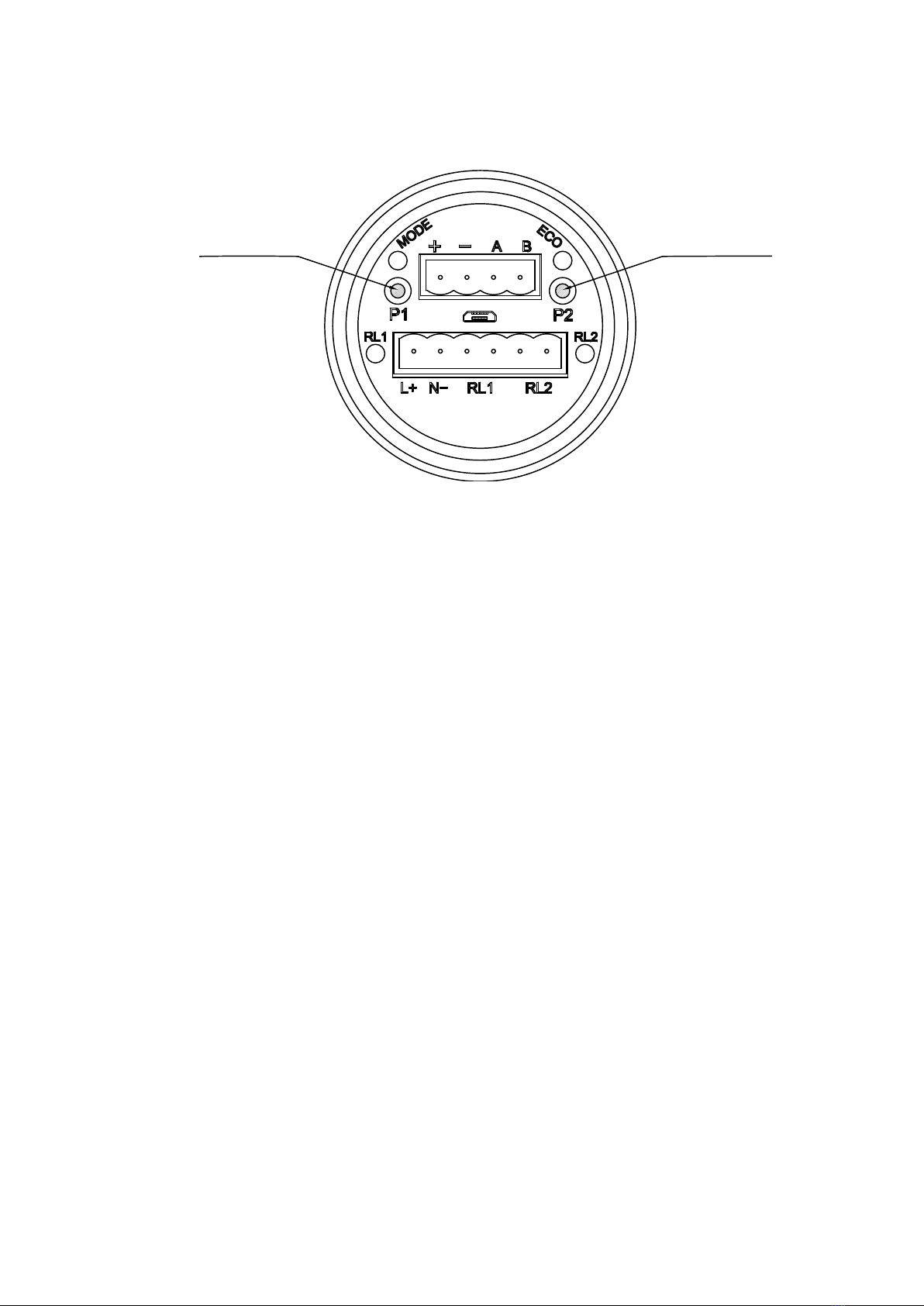
7.2 VIA 2 BUTTONS CALIBRATIONS (“1” VERS. ONLY)
RPL81has2buttonsonboard,P1andP2,withwhichitispossible:
- to program the level measurement range via the 4mA and 20mA distances self-acquisition
- to program the RL1 and RL2 thresholds via the switching distances self-acquisition.
Buttom P2Buttom P1
7.2.1 4mA DISTANCE
To set the 0% level measurement (4mA) it is necessary that the real level is the one corresponding to the
“4mA Distance”; alternatively it is possible to place a target orthogonally to the RPL81 transmitter at a distance equivalent
tothe0%level.WaituntiltheECOLEDashesforatleast30s,presssimultaneouslyP1andP2,
release them and verify that the ECO LED remains turned on.
PressP1twotimesandwaitfortheECOLEDashes.
The distance has been saved and automatically associated with the 0% level (4mA).
7.2.2 20mA DISTANCE
To set the 100% level measurement (4mA) it is necessary that the real level is the one corresponding to the
“20mA Distance”; alternatively it is possible to place a target orthogonally to the RPL81 transmitter at a distance equivalent
to the 100% level.
WaituntiltheECOLEDashesforatleast30s,presssimultaneouslyP1andP2,releasethemandverifythattheECOLED
remains turned on.
PressP2twotimesandwaitfortheECOLEDashes.
The distance has been saved and automatically associated with the 100% level (4mA).
7.2.3 RL1 MAX LEVEL THRESHOLD DISTANCE
TosettheRL1maximumlevelalarmthresholdisnecessarythatthereallevelistheonecorrespondingtothe
“RL1max.lev.thresholddistance”;alternativelyitispossibletoplaceatargetorthogonallytotheRPL81transmitterat
a distance equivalent.
WaituntiltheECOLEDashesforatleast30s,presssimultaneouslyP1andP2,releasethemand
verifythattheECOLEDremainsturnedon.PressP2andthenP1andwaitfortheECOLEDashes.
The distance has been saved and automatically associated with the RL1 threshold (see default level alarm threshold
settings on page 21)
7.2.3 RL2 MIN LEVEL THRESHOLD DISTANCE
TosettheRL2maximumlevelalarmthresholdisnecessarythatthereallevelistheonecorrespondingtothe
“RL2 min. lev. threshold distance”; alternatively it is possible to place a target orthogonally to the RPL81 transmitter at a
distance equivalent.
WaituntiltheECOLEDashesforatleast30s,presssimultaneouslyP1andP2,releasethemand
verifythattheECOLEDremainsturnedon.PressP1andthenP2andwaitfortheECOLEDashes.
The distance has been saved and automatically associated with the RL2 threshold (see default level alarm threshold
settings on page 22)

Page 16 of 40 www.sgm-lektra.com
RPL81 - conguration modes
7.3 CALIBRATION / CONFIGURATION VIA VL620/VL621
The VL620/VL621 programming module can be mounted and removed from the RPL81 without
aectingtheunitoperation.Unscrewingthecap(“1”vers.),theVL620modulecanbeconnectedor
disconnected. For “2” version connect the VL621 module directly to the unit.
TheVL620/VL621moduleareequippedwithmatrixLCD.
N:B: When the VL620/VL621 is connected the communication via MODBUS is inhibited.
ToinsertthemicroUSBconnectorconnectorcorrectly,thefollowingprocedureisrecommended:
1) disconnect the 2 removable terminals.
2) insert the male micro USB socket of the supplied cableinto the female micro USB socket present between the 2
removable terminals.
3) connect the 2 removable terminals.

Page 17 of 40
www.sgm-lektra.eu
8.1 VL620/VL621 FEATURES
The VL620/VL621 program module has 4 buttons which allow to perform all operational, control and programming instrument
functions.Inthecongurationmenus,ispossible:
1. Submenus and parameters access; press to select and press to access.
2. Parameteroptionschoice:Press to select the option and press to store the option.
Press toexitwithoutstoring.
3. Conguretheparametervalues;insomeparametersthecongurationisdonebysettingavalue(eg.,inthe
SETDISTANCE4mAparameterispossibletochangethethecorrespondingdistancevalue,inmm):
press toselectthedigittobemodied(thedigitishighlightedininverse),press to change the high
lighted digits number, press tosavethesetvalueandexitautomatically.
Press toexitwithoutstoring.
LEFT ARROW button:
• Exit conguration
• Back to previous menu
UP ARROW button:
• Parameter values modication
• Parameter scroll
SCROLL button:
• Cursor movement (to the right)
• Parameter scroll
ENTER button:
• Conguration access
• Options conrmation
• Parameters values conrmation
RPL81 - operator interface
8-OPERATOR INTERFACE
Displayed at the bottom indicates the correct echo signal reception
!Displayed at the top alerts that there is a generic error; press SCROLL to show the message that
indicates the present error type.
The RPL81 returns automatically to RUN mode.
QUICK SETUP-Menuwitheasyaccessforquickbasicparametersconguration.
Toaccess:from“RUN”modepressENTERtothequicksetupmenumodeaccess,LEFTARROWtoexit.
ADVANCED SETUP - Full menu with access to all parameters, including functional parameters.
It is recommended to carefully read the complete documentation before accessing.
Toaccess:from“RUN”mode,holdingdownUPARROW,pressENTERtotheadvancedcongurationmode
access,LEFTARROWtoexit
Page 18 of 40 www.sgm-lektra.com
Set Distance 4mA
Set Distance 20mA
Max Distance
Filter Coefficient
Blind Distance
Display
RL1 Threshold
RL2 Threshold
Set Distance 4mA
0000 mm
Set Distance 20mA
0000 mm
Filter Coefficient
000
Blind Distance
0000 mm
RL1 Threshold
0000 mm
RL1 Threshold
0000 mm
Distance mm
Level mm
Level %
Output mA
Parameter Default Values
10000mm
00000mm
20
60mm
Distance mm
0mm (Disabled RL1)
0mm (Disabled RL2)
500mm
Max Distance
00000mm
RPL81 - quick setup
9-QUICK SETUP
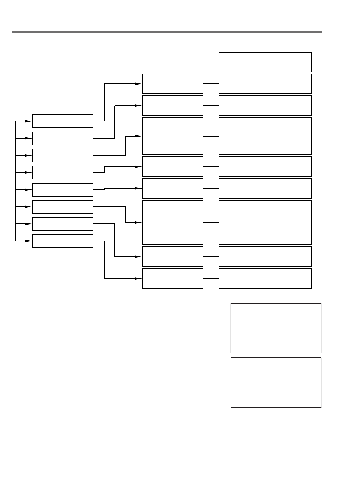
9.1 - Quick Setup menu structure
9.2 - QUICK SETUP MODE
From “RUN” mode press ENTER to access the Quick Setup menu.
SelecttheparametersbymovingthecursorwithSCROLL,andconrm
withENTER;pressLEFTARROWtoexit.
4321
D
mm
SET DISTANCE 4mA
SET DISTANCE 20mA
MAX DISTANCE
FILTER COEFFICENT
BLIND DISTANCE
DISPLAY
RL1 THRESHOLD
RL2 THRESHOLD
►

Page 19 of 40
www.sgm-lektra.eu
RPL81 - quick setup
9.2.1 SET DISTANCE 4mA
Press ENTER to display the distance value associated with 4mA output.
UseSCROLLandUPARROWtomodifythatvalue;intheexamplethe
4mA distance is 3500mm.
PressENTERtoconrm.
9.2.2 SET DISTANCE 20mA
Press ENTER to display the distance value associated with 20mA output.
UseSCROLLandUPARROWtomodifythatvalue;intheexamplethe
20mA distance is 500mm.
PressENTERtoconrm.
SET DISTANCE 4mA
SET DISTANCE 20mA
MAX DISTANCE
FILTER COEFFICENT
BLIND DISTANCE
DISPLAY
RL1 THRESHOLD
RL2 THRESHOLD
►
3500 mm
SET DISTANCE 4mA
SET DISTANCE 4mA
SET DISTANCE 20mA
MAX DISTANCE
FILTER COEFFICENT
BLIND DISTANCE
DISPLAY
RL1 THRESHOLD
RL2 THRESHOLD
►
0500 mm
SET DISTANCE 20mA
100%
0%
20mA Distance
4mA Distance
Lelev measurement
RPL81
Reference point

Page 20 of 40 www.sgm-lektra.com
RPL81 - quick setup
9.2.3 MAX DISTANCE
PresstheENTERkeytodisplaythepreviouslysetmaximumdistancevalue.
TheMAXDISTANCEisusedtopreventthesensorfromdetectinganechosignal
at a distance .
UseSCROLLandUPARROWtomodifythevalue;intheexample,themaximum
measurement distance is 3600mm.
The function is disabled with the value set to 00000mm.
ToconrmpressENTER.
SET DISTANCE 4mA
SET DISTANCE 20mA
MAX DISTANCE
FILTER COEFFICENT
BLIND DISTANCE
DISPLAY
RL1 THRESHOLD
RL2 THRESHOLD
►
00000 mm
MAX DISTANCE
4mA Distance
Max Distance
Reference Point
RPL75
Other manuals for RPL81
1
Table of contents
Other SGM LEKTRA Transmitter manuals

SGM LEKTRA
SGM LEKTRA PTU50 User manual

SGM LEKTRA
SGM LEKTRA PTU50 Guide

SGM LEKTRA
SGM LEKTRA METER Series Quick start guide

SGM LEKTRA
SGM LEKTRA RPL75 User manual

SGM LEKTRA
SGM LEKTRA METER Guide

SGM LEKTRA
SGM LEKTRA PTU05 User manual

SGM LEKTRA
SGM LEKTRA PTU51 User manual

SGM LEKTRA
SGM LEKTRA FLOWMETER Guide

SGM LEKTRA
SGM LEKTRA KPT Guide

SGM LEKTRA
SGM LEKTRA MTU5 User manual


Popular Transmitter manuals by other brands


Burkert
Burkert 8312 Series operating manual

Transmitter Solutions
Transmitter Solutions Stinger Quick manual

ARJAY ENGINEERING
ARJAY ENGINEERING EC-Gold Dual user manual

triopo
triopo TR-F3-RT instruction manual

Motorola
Motorola SG4-DRT-2X Installation sheet
uAvionix
uAvionix skyBeacon STC Maintenance manual


