SGM LEKTRA MTU5 User manual

MTU5
Ultrasonic level transmitter 825B136A
Process Control and Measurement
Factory Test Certificate
In conformity to the company and check procedures I certify that the equipment:
MTU5...................................... Production and check date: ................................
Serial n. .......................................................
is conform to the technical requirements on Technical Data and it is made in conformity to the SGM-LEKTRA procedure
Quality Control Manager .................................
Warranty
Products supplied by SGM LEKTRA are guaranteed for a period of 12 (twelve) months from delivery date according to
the conditions specified in our sale conditions document.
SGM LEKTRA can choose to repair or replace the Product.
If the Product is repaired it will mantein the original term of guarantee, whereas if the Product is replaced it will have 12
(twelve) months of guarantee.
The warranty will be null if the Client modifies, repair or uses the Products for other purposes than the normal conditions
foreseen by instructions or Contract.
In no circumstances shall SGM LEKTRA be liable for direct, indirect or consequiential or other loss or damage whether
caused by negligence on the part of the company or its employees or otherwise howsoever arising out of defective goods
Technical Data
Housing material: PC / PP wetted part
Mechanical installation: DN150 PP flange or bracket
Protection degree: IP67 / IP68 (sensor)
Electrical connection: Internal push connectors
Workingtemperature: -30÷+70°C;+80°C non-continuous
Pressure: from 0,5 to 1,5 bar (absolute)
Powersupply: 24Vdcor24,115,230Vac(specifyattheorder)
Power consumption: max 1,5W
Analog output: 4÷20mA, max 750ohm
Relays output: n°2 3A 230Vac (n.o.)
Digital communication: MODBUS RTU
Max measure range: max 0.5÷12m
[In case of non perfectly reflecting surfaces, the maximu
distance value will be reduced]
Blind distance: 0,5m
Temperature compensation: digital from -30 to 80°C
Accuracy: ±0,5% (of the measured distance)
not better than ±3mm
Resolution: 1mm
Calibration: 4 buttons or by MODBUS RTU
Warm-up: 5 minutes typical
LCDDisplay: Plug-indisplay/keyboard4buttonsmatrixLCD

Page 2 of 28
MTU5 - Safety / Mechanical installation
2. INSTALLATION
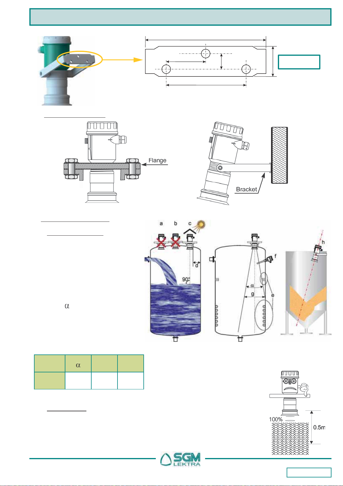
2.1 MECHANICAL DIMENSIONS
The MTU5 transmitter has the DN150 PN6 UNI 1092-1/PP flange or bracket connection.
1. SAFETY
1.1 Installation precaution
a) Installation shall only be performed by qualified personnel and in accordance with local governing regulations.
b) Make sure that the working temperature is between -30 and +70 ° C, +80 ° C non-continuous.
c) Installthetransmitterina its physicalcharacteristicsand housing/sensorconstructionmaterials compatibleenvironment.
d) The transmitter must be used safety warnings observance.
e) Improper transmitter use would cause serious damage to people, to the product and connected equipment.
Fig.3
The non intrusive system application is now preferred in the level measurements field. For this reason the
SGM-LEKTRA developed the MTU5 unity to best meet the “GENERAL-PURPOSE” application requests. The MTU5 unit
offers, together with its compact size, a complete versions range that makes the MTU5 very versatile for the most varied
applications, including areas with explosion hazard and chemically aggressive environments. MTU5 is an ultrasonic level
transmitter, temperature-compensated and suitable for connection with MODBUS RTU acquisition systems. MTU5 is a
compact unit which in addition to an analog output includes two freely addressable relay.
Non-contact level measurements
Suitable for liquids and granulates level
measurement
Integrated digital temperature sensor
to compensate the measure
MODBUS RTU com. protocol
24Vdc or 24, 115, 230Vac power s.
Mechanical protection: IP67 / IP68 (sensor)
Output: 1 4÷20mA analog output
2 relays output
DN150 flange
(Cod.2)
Fig.1 Fig.2
Anticondensation
filter (M/N code)
Drilling template
view (fig.3)
Bracket
(Cod.4)
Page 3 of 28
MTU5 - Mechanical installation
2.3.1 Blind distance
During installation is important to remember that in the sensor vicinity there is a blind
zone (or BLIND DISTANCE) of 0.5m where the sensor can not measure.
2.3 Mounting precautions
2.3.1 Mounting position (Fig.6)
- With cambered roof, Do not install the
sensor in the tank center (b).
Leave a 500mm minimum distance
between the sensor and the tank
smooth wall (d).
- Use a protective cover to protect the
sensor fromweatheranddirectsunlight(c).
- Donotinstallthesensorneartheloadzone(a).
- Make sure that in the sensor emission
beam(lobe“ ”)therearenoobstacles
(f,s) that can be intercepted as level.
- Make sure that there is not foam
presence on the product surface to be
measured
Tab.1
Liquids Bulk solids
Fig.6
Lobo
“ “ Lg
MTU5 10° 12m 2m
(12m)
2.2 Mounting examples
Fig.4
Fig.5
Drilling template
view
Fig.7
75mm
37.5mm
20mm
122mm
35mm
Fig.3
Page 4 of 28
MTU5 - Mechanical installation
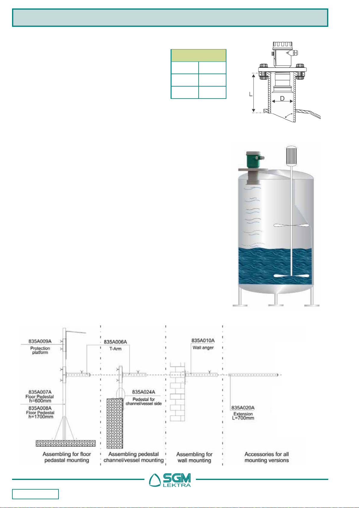
2.3.6 Mechanical installation accessories
Fig.10
2.3.5 Agitators presence
The level measurement is possible thanks to the Auto-Tuned statistical filter.
Should rarely need to adjust the filter setting by editing 2 MTU5 sensor
programming parameters:
- FILTER; this parameter is present in the Quick Setup menu (page 9)
and in the Advanced Configuration “SETUP” menu (page 16);
increasing the parameter value, decreases the sensor sensitivity to the
level measurement sudden variations.
- F-WINDOW; this parameter is present in the Advanced Configuration
“SERVICE” menu (page 26); decreasing the parameter programmed
value, increases the sensor immunity to false echoes.
Fig.9
MTU5 can be installed in an extension pipe
(see Figure 8) to turn away the sensor from
the maximum level point. The extension pipe
must be flat and without joints (welds, etc..),
also, the pipe terminal part must be cut at 45°
and with the borders without burr.
MTU5
D (mm) Lmax(mm)
80 240
100 300
Tab.2
Fig.8
Page 5 of 28
MTU5 - Connections and Configuration
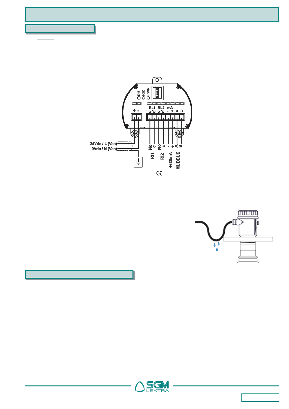
3. CONNECTIONS
3.1 Wiring
1) Separate the engine control cables or power cables from the MTU5 connection cables..
2) Open the cap by unscrewing.
3) Lead the cables into the transmitter through the glands.
4) Do not use sleeves terminals, because they might interfere with the VL601 module insertion
5) Close the cap and tighten the cable glands.
3.2 Humidity infiltrations
4. CONFIGURATION MODES
The MTU5 have 2 configuration/calibration modes:
- via MODBUS RTU, by PC, for 4-wires versions
- via VL601 programming module
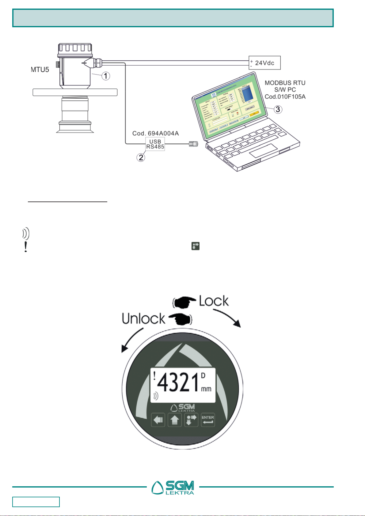
4.1 Via MODBUS RTU
4.1.1 MODBUS RTU PC connection (fig.13)
1) MTU5 with MODBUS RTU communication protocol
2) USB/RS485 interface module, cod.694A004A
3) MODBUS RTU communication S/W, cod.010F105A (3), for MTU5 transmitter
With this software is possible:
- connect, by selecting the UID address, the MTU5 transmitters in MODBUS RTU network
- read on your PC monitor all measures in reading and MTU5 operation data
- programming all MTU5 configuration parameters
- storing on files, data logger function; MTU5 measures in reading and operating states
To avoid the humidity infiltration inside the housing is recommended:
- forelectricalconnections, usea cablewith a 6÷12mm outer diameterand
fully tighten the M20 cable gland
- fully tighten the cap
- position the cable so that it forms a downward curve at the M20 output
(Fig. 12); in this way the condensation and/or rain water will tend to drip
from the curve bottom
For installations with a strong humidity/vapor presence the version with
the optional anti-condensation filter (cod.M/N) is available Fig.12
The immunity to electromagnetic interference complies with Directives
Fig.11
Page 6 of 28
4.3 via VL601 configuration
The VL601 programming module can be mounted and removed from the MTU5 without affecting the unit operation.
Unscrewing the cap, the VL601 module can be mounted (by clockwise rotation until it clicks) or dismounted (by
rotation counterclockwise) as shown in Fig.14. The VL601 module is equipped with matrix LCD.
displayed at the bottom indicates the correct echo signal reception
displayedat thetop alertsthat thereis ageneric error;press to showthe messagethat indicatesthe present
error type.
The MTU5 returns automatically to RUN mode.
MTU5 - Configuration
Fig.13
Fig.14
Page 7 of 28
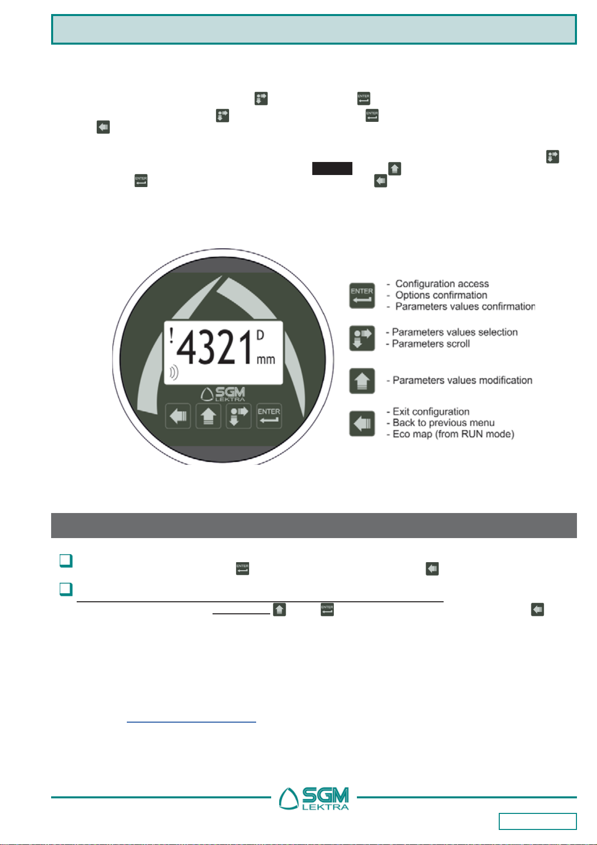
The VL601 program module has 4 buttons (fig. 15) which allow to perform all operational, control and programming
instrument functions.
In the configuration menus, is possible:
a) Submenus and parameters access; press to select and press to access.
b) Parameter options choice: Press to select the option and press to store the option.
Press to exit without storing
c) Configure the parameter values; in some parameters the configuration is done by setting a value (eg., in the
SET DISTANCE 4mA parameter is possible to change the the corresponding distance value, in mm): press to
select the digit to be modified (the digit is highlighted in inverse ), press to change the highlighted digits
number, press to save the set value and exit automatically. Press to exit without storing .
In the display top right, during the settings, there is always a number, eg. “1.2”. This number is the menu or
parameter index that’s displayed. The menu structure is represented on page 8 and on pages 13÷14.
MTU5 - Configuration
Fig.15
WiththeVL601 module is possible to access two configuration modes for the MTU5 setting:
QUICK START - Menu with easy access for quick basic parameters configuration.
To access: from “RUN” mode press to the quick setup menu mode access, to exit
ADVANCED CONFIGURATION - Full menu with access to all parameters, including functional parameters.
It is recommended to carefully read the complete documentation before accessing.
To access: from “RUN” mode, holding down , press to the advanced configuration mode access, to exit
WARNING! -The documentationprovidedwiththeMTU5containthemostfrequently
used indications. If it’s necessary refer to the full manual, it can be downloaded from
our website www.sgm-lektra.com , in the products section.

Page 8 of 28
5. QUICK START MODE
MTU5 - Quick Start
From “RUN” mode press
to access the Quick
Setup menu
Select the parameters by
moving the cursor with ,
and confirm with ;
press to exit
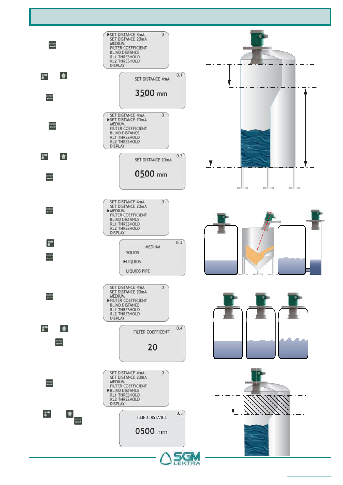
5.1 Quick Setup menu structure
Page 9 of 28
MTU5 - Quick Start
4mA distance
20mA distance 100%
0%
Level
measurement
MTU5
reference point
t
t
t
t
Fig.16
5.2.3 MEDIUM
5.2.5 BLIND DISTANCE
5.2.4 FILTER COEFFICIENT
5.2.1 SET DISTANCE 4mA
Press to display the
distance value associated
with 4mA output.
5.2.2 SET DISTANCE 20mA
Press to display the pre-
vious setting
Press to select the me-
dium type.
Press to confirm.
In fig.17 product selection
example.
Press .TheBLIND ZONE
is used to avoid undesi-
red measures near to the
transmitter
Use and to modify
the value. Press to con-
firm. The minimum value is
500mm.
Press . Increasing the
valueslows down the sensor
response speed.
Use and tomodify the
value.Input a value from 1to
99. Press to confirm.
In fig.18 value choice exam-
ple.
Use and tomodifythat
value;in the Fig.16 example,
the4mAdistanceis3500mm.
Press to confirm.
Press to display the
distance value associated
with 20mA output.
Use and tomodifythat
value;in the Fig.25 example,
the20mAdistanceis500mm.
Press to confirm.
SOLIDS
LIQUIDS
LIQUIDS
PIPE
Fig.17
Fast resp.
5÷10 Normal resp.
20 Slow resp.
40÷100
Fig.18
BLIND
DISTANCE
BLIND
ZONE
MTU5
reference point
t
t
t
Fig.19

Page 10 of 28
MTU5 - Quick Start
5.2.6 RL1 THRESHOLD
Press to display the
previous setting. Set the
distance from the sensor
Use and tomodify the
value; in the fig.20 example
the RL1 max. level threshold
distance is 700mm.
Press to confirm.
NB-RL1 inactive with
0000mm
When confirming with the button the maximum level threshold value storage, in the example 700m (figures 20 and
21), the MTU5 activates RL1 with the following default settings for level alarm threshold:
1) MIN / MAX = MAX; maximum level alarm
2) DELAY = 0 sec.; no switching delay
3) SECURITY = YES; relay de-energized, and contact open, during the maximum level alarm
4) ENABLE / DISABLE = ENABLE; alarm threshold function enabled
To change these relay settings is necessary to access the advanced setup menu (pag.16) and any subsequent changes
to the RL1 threshold value not affect the relay custom settings.
RL1
THRESHOLD
Max level
alarm zone
MTU5
reference
point
700mm
Fig.20
RL1
SET
RL1 "ON"
RL1 "OFF"
RL1 RL1
Level
RL1, MAX LEVEL ALARM
RL1 RL1
RL1
RL1
Max
Alarm Max
Alarm
MTU5
reference
point
RL1
THRESHOLD
Max. level
alarm zone
700mm
RL1
Fig.21

Page 11 of 28
MTU5 - Quick Start
5.2.7 RL2 THRESHOLD
Press to display the
previous setting. Set the
distance from the sensor
Use and tomodify the
value; in the Fig.22 example
the RL2 min. level threshold
distance is 9000mm.
Press to confirm.
NB-RL2 inactive with
0000mm
When confirming with the button the maximum level threshold value storage, in the example 3000mm (figures 22 and 23),
the MTU5 activates RL2 with the following default settings for level alarm threshold:
1) MIN / MAX = MIN; minimum level alarm
2) DELAY = 0 sec.; no switching delay
3) SECURITY = YES; relay de-energized, and contact open, during the maximum level alarm
4) ENABLE / DISABLE = ENABLE; alarm threshold function enabled
To change these relay settings is necessary to access the advanced setup menu (pag.16) and any subsequent changes
to the RL2 threshold value not affect the relay custom settings.
MTU5
reference
point
RL2
THRESHOLD Min. level
alarm zone
3000mm
Fig.22
RL2 RL2
SET
RL2 "ON"
RL2 "OFF”
RL2 RL2
Level
RL2, MIN. LEVEL ALARM
RL2 RL2
RL2 RL2
Min.
Alarm Min.
Alarm
MTU5
reference
point
RL2
THRESHOLD
Min. level
alarm zone 9000mm
Fig.23
Page 12 of 28
MTU5 - Quick Start
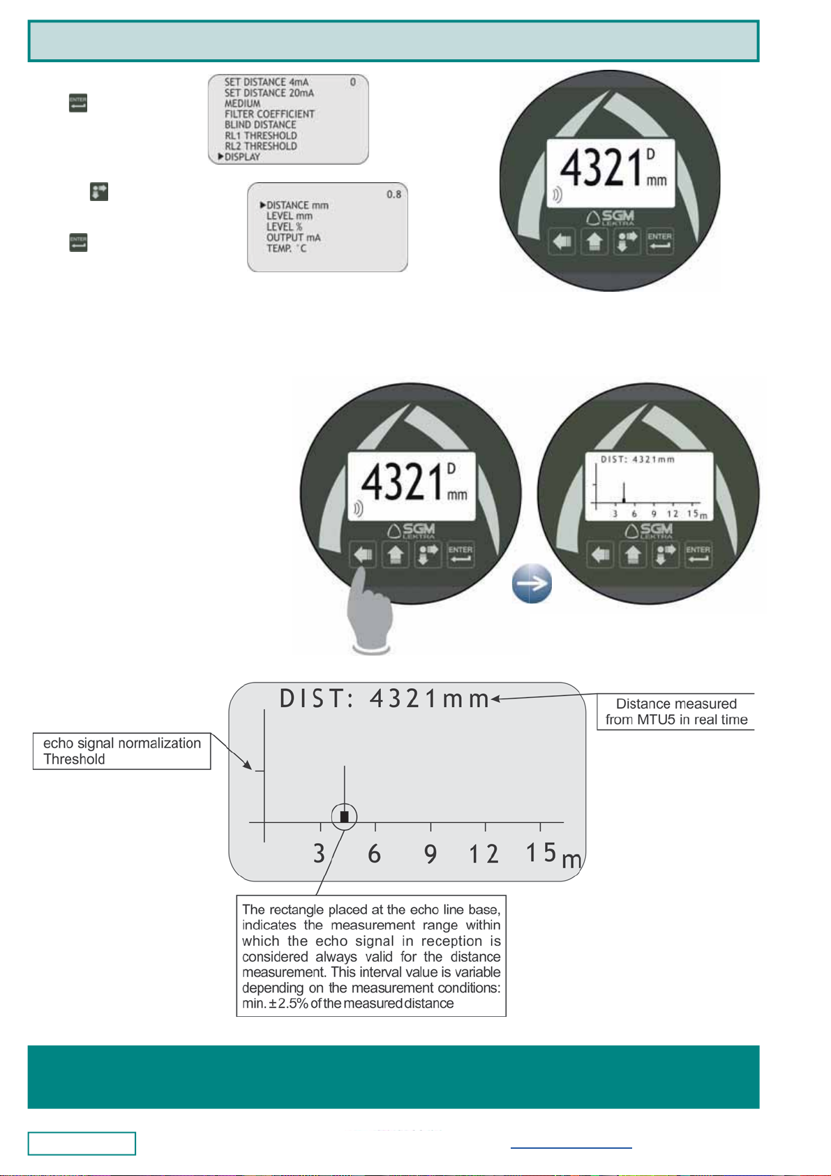
5.2 ECHO MAP
Pressing the BK, from RUN mode, to access
directly to the echoes digital map display,
which are in MTU5 receiving (Fig.25).
This function is useful for:
- properly orient the transducer
pointing.
- verify the echoes in acquisition
correctness.
- identify any false echo signals
that may cause measurement
errors.
Fig.24
Fig.25
Documentation subject to technical change with no prior warning
SGM-LEKTRA S.r.l. Via Papa Giovanni XXIII, 49 - 20090 Rodano (MI) - ITALY-
tel: ++39 0295328257 fax: ++39 0295328321
web: www.sgm-lektra.com e-mail: [email protected]
Pagesfrom13to28(fullmanual)canbedownloadedfromourwebsitewww.sgm-lektra.comintheproductssection
5.2.8 DISPLAY
Press to access the set-
tings change.
With the button is pos-
sible to select the data to
display
Press to confirm.
Table of contents
Other SGM LEKTRA Transmitter manuals

SGM LEKTRA
SGM LEKTRA PTU51 User manual

SGM LEKTRA
SGM LEKTRA PTU50 User manual

SGM LEKTRA
SGM LEKTRA METER Guide

SGM LEKTRA
SGM LEKTRA RPL81 User manual

SGM LEKTRA
SGM LEKTRA FLOWMETER Guide

SGM LEKTRA
SGM LEKTRA KPT Guide

SGM LEKTRA
SGM LEKTRA TC26 User manual

SGM LEKTRA
SGM LEKTRA RPL75 User manual

SGM LEKTRA
SGM LEKTRA PTU50 Guide

SGM LEKTRA
SGM LEKTRA RPL81 User manual


Popular Transmitter manuals by other brands


Danfoss
Danfoss AKS 32 installation guide

Cooper Menvier
Cooper Menvier 705r installation guide

Omega
Omega TX31 user guide

ZachTek
ZachTek WSPR quick start guide

EUTECH INSTRUMENTS
EUTECH INSTRUMENTS ALPHA TDS 200 TOTAL DISSOLVED SOLIDS... instruction manual

Panasonic
Panasonic Ramsa WX-RP410 operating instructions


