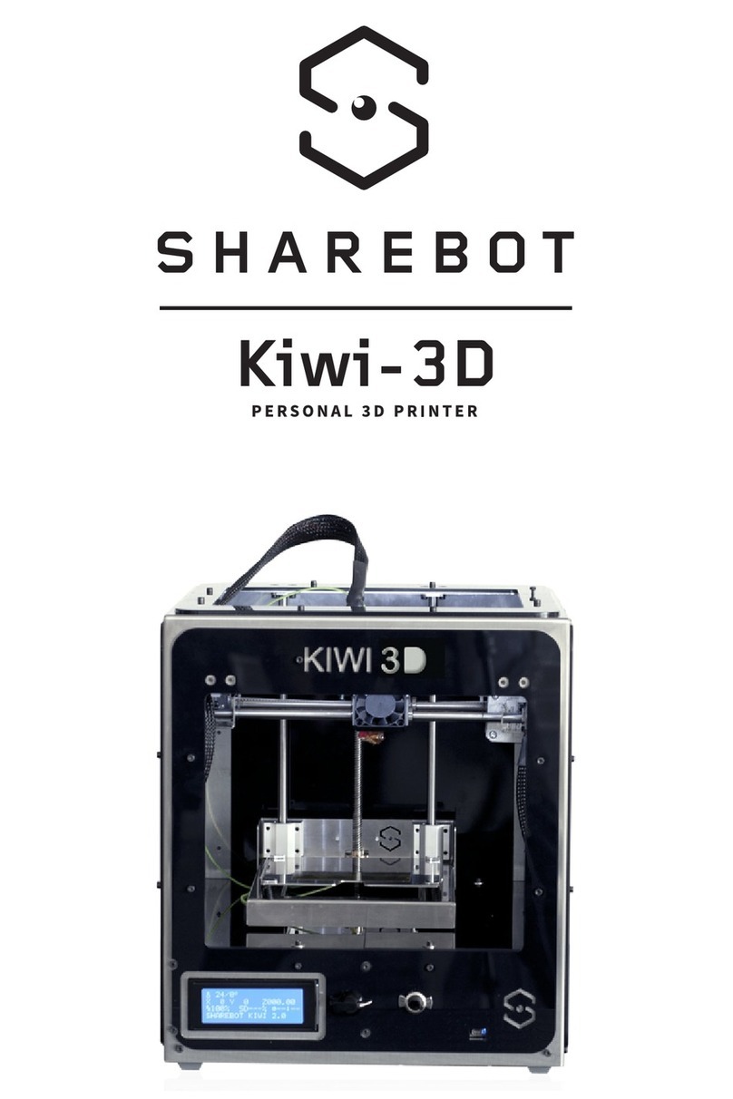
SHAREBOT Kiwi-3D User manual


1 | Introduction

4
Dear Sharebot operator, we are thrilled that you have chosen to side in the fore-
front of this new industrial revolution. As with any new technology, the pioneers
like yourself are the ones who’ll drive true innovations. Your new Sharebot 3D
printer will make you free to create all the objects you can imagine. The new de-
sign of this Sharebot’s printer incorporates all the experience gained from previ-
ous models of Sharebot 3D printers and we’re extremely proud of this new model.
Your input will help us to constantly improve Sharebot 3D printers and it will
innovation so please share your experiences on www. kiwi3dworld.com
We look forward to see what you build!
Sharebot team
KIT contents: if at the end of the installation you will exceed some of the parties,
keep them because they’ll be useful as spare parts in the future. cosa realizzerai!
1 | Introduction
2 | Parts List

7
FOIL KEY:
A – Main structure
B – Bottom tray
C – Z Plan
D – Printing bed
F - carriage X
O – Hotend Plate
P - Lead-carrier Y Z
Q – Lead-carrier X

9
METHACRYLATE CARTER KEY:
A – Frontal carter
B – Head carter
C – Right carter
E- Rear carter
G – Right deep end carter
P1 – Reel carrier
P2 - Reel carrier
P3 - Reel carrier
P4 - Reel carrier

2 | Parts list 2 | Parts list
10 11

12
2 | Parts list
2 | Parts list

3 | Assembling the base
The screws can become loose due to shock and vibration: to avoid spontaneous
loosening of the screws it is recommended that you put brakes on all screws threads
between the threaded couplings. Tip: Loctite 221-brakes low-resistance threaded for
remember you each time where to apply this trick. For the lubrication of worm of the
Z axis, bearings and guides we recommend the use of vaseline oil or sewing machine
oil. The ShareBot Kiwi-3D assembly Kit, is an advanced kit and requires good manual
dexterity skills and ability to tin solder for a correct assembly.
2 | Lista delle Parti

3 | Assembling the base
Fig. 1
10. Fan 40x40
11. Screws M3x6 8
12. Screws M3x10 2
_
Fig. 2
Take the bottom plate of the printer and turn it so that the edges have relieved
geared down. Remove the plastic protective sheet.
_
Fig. 3
Take the four rubber pins, and separate them.
1
23
17

Fig. 4
Stick the 4 rubber pins to the base’s angles.
_
Fig. 5
position you can locate the holes. Pictured are highlighted with coloured areas:
purple for the target Z-guides, green for the Z axis engine, Orange for the control
card, yellow for the fan.
_
Fig. 6
Get 4 pads lock guides. Begin to position the plates block guide to 2 pairs on the
respective holes, and point it using 2 screws M3x6 for every lead carrier.
_
Fig. 7
To center the screws before thighten them, you can use the axis Z guides D8x338.
_
Fig. 8
_
Fig. 9
the base, using 4 screws M3x6. Do not tighten too strong or there’s the risk to dam-
age the nylon threads. In this case you don’t need to use the brakes-threads.
4
6
8
5
7
9
3 | Assembling the base
19

Fig. 10
Get a 40mm fan, place the fan with its label facing downwards and the power cord
to the edge of the circuit board, connect the power connector as shown in photo,
center using 2 M3x10 screws.
_
Fig. 11 and 12
_
Fig. 13 and 14
O-rings. The O-rings are usuful to dampen engine vibrations. Insert the screws in
the positions 2 and 4 on the side of the rubber pin, now in the other side of the tray
insert on the screws the two o-rings and then approaches the Z engine and secure
it with the two screws then tighten doing attention that the two o-rings remained
under the engine, it is important to tighten the two screws with the same force.
Parades the bar cover and unscrew the brass bushing from the nut screw Z.
10
12
14
11
13
3 | Assembling the base
21
3
1

3b | Assembling the printing plate

3b | Assembling the printing plate
Fig. 1
1. Z Foil
2. 2 Linear bearings D8 in a toolbox
3. 8 Screws M4x8
4. 4 Screws M3x25 4
5. 4 Springs D10
6. Foil printing bed
7. Safety adhesive
8. 2 Nylon spacers m3x10
9. 5 Screws M3x6
10. Brass bushing nut screw Z
11. End-stop sensor
_
Fig. 2
Take the workplate and the printing plate and remove the protection plastic layer.
_
Fig. 3 e 4
Position the two bearing to the limit of the workplate’s carriage and tighten with four
screw from the Z engine and tighten to Z plate using three screws M3x6.
1
2 3
25

3b | Assembling the printing plate
Fig. 5
Tighten the end-stop to the two nylon spacers. Use two M3x6 screws orienting
tab upwards.
_
Fig. 6
Take the printing bed and stick on it the safety indication adhesive, keep the loop
_
Fig. 7 e 8
Now slide, the four M3x25 screws from the top on the printing bed, then place on the
screws the four springs D10 and tighten the workplate to the Z plane, leaving the print-
advisable to use the lock screws threads between print and plate Z-plane.
4
6
8
5
7
27

3c | Assembling the carriage

3c | Assembling the carriage
Fig. 1
To assemble the carriage, looks in the kit the components you see in the picture:
1. Right lateral blocker
3. Stepper engine with a pulley
3. 8 bearings LMU88
4. 12 seiger
5. 4 nylon bearing supports
6. 2 nylon spacers M3x10 and 2 nylon spacers M3x20
7. 20 M3x6
8. 8 thin sheets lead-carrier X
9. Belt T2,5 500
10. 1 M3x25
11. 1 selblocking nut M3
13. 2 Final leg 14. 2 m3 x10
15. Pulley T2,5 16
_
Fig. 2
carriers into the proper threaded holes as you can see in the photo. The bearing car-
riers are to be positioned inside the abutment.
_
Fig. 3
Take the X lead carriers tag, if you think is necessary clean the tag’s hole with sand-
paper, it could be a residual that does not permit the perfect joint. Using two screws
-
arriving on the abutment foil, you can do this operation by pushing to laterally the
second tag with a screwdriver while you are verifying that the system doesn’t move.
1
2 3
31

3c | Assembling the carriage
Fig. 4 e 5
M3x25 screw.
_
Fig. 6
Insert the pulley into the belt, then insert all in the lateral block while pointing the
-
sary to force it.
_
Fig. 7
If you don’t have already do it, insert the two leads D8 in the proper sites.
_
Fig. 8
Take 2 bearings LM8UU and, using a Seiger pliers, assemble 2 Seiger rings for every
bearing.
_
Fig. 9
Assemble two bearings boxing-in the nylon bearing carriers previously assembled
4
6
8
5
7
9
33

3c | Assembling the carriage
Fig. 10
Now take the 4 bearings LM8UU and build on them a seiger ring for every bearing,
remember to use the plicers. Insert the 4 bearing LM8UU with only one seiger on
_
Fig. 11
Assemble the right abutment, take the right abutment and fasten with the two ny-
the 4 X lead carriers thin sheet and secure them with two screws M3x6 in the proper
two bearing LM8UU and assemble the four seigers. Boxing-in the two bearing into
their nylon bearing carriers.
_
Fig. 12 e 13
photo shows you. Take the spacers M3x20 and tighten as shown in the photo for the
_
Fig. 14
pass between the already pointed seigers.
_
Fig. 15
10
12
14
13
15
11
35
Y
X

3c | Assembling the carriage
Fig. 16
Insert the right abutment on the X leads, boxing-in the thin sheet till the end of it.
Take the stepper engine with integrated gear wheel, pointing the connector socket
two screws M3x6 in the securing loop and in the engine’s holes.
_
Fig. 17 e 18
Take two screws M3x10 and point the to the threaded holes that are on the top part
of the carriages, they will be helpful later to tend the Y belts.
16
18
18
17
17
37

3d | Assembling X Carriage
and the extruder
Other manuals for Kiwi-3D
1
Table of contents
Other SHAREBOT 3D Printer manuals
