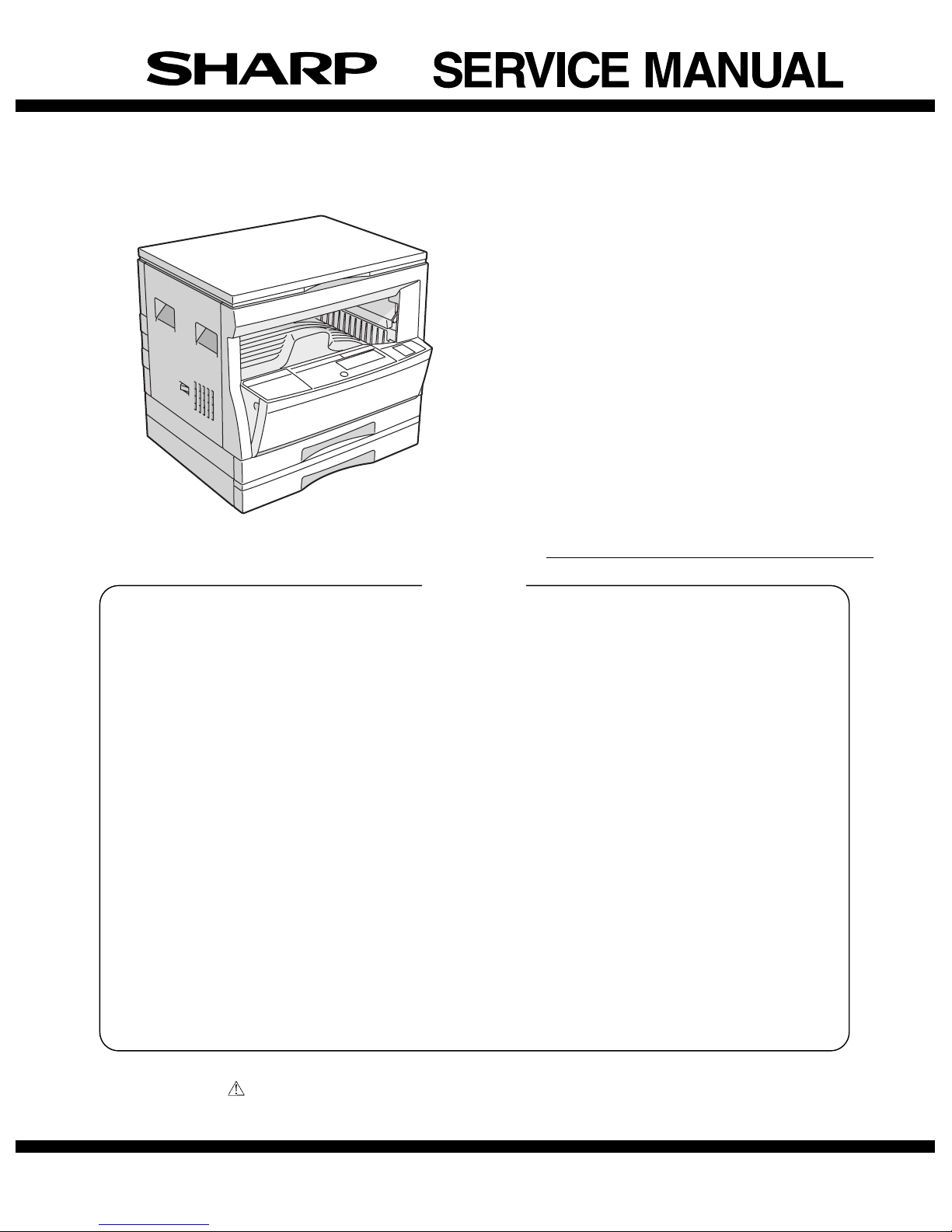
Sharp AR-162 User manual

CODE: 00ZAR162//A1E
DIGITAL COPIER
AR-162
AR-163
AR-201
AR-206
AR-207
MODEL AR-F201
Parts marked with " " are important for maintaining the safety of the set. Be sure to replace these parts with specified
ones for maintaining the safty and performance of the set.
[ 1 ] GENERAL . . . . . . . . . . . . . . . . . . . . . . . . . . . . . . . . . . . . . . . . . . . . . . . .1-1
[ 2 ] SPECIFICATIONS . . . . . . . . . . . . . . . . . . . . . . . . . . . . . . . . . . . . . . . . . . 2-1
[ 3 ] CONSUMABLE PARTS . . . . . . . . . . . . . . . . . . . . . . . . . . . . . . . . . . . . . 3-1
[ 4 ] EXTERNAL VIEWS AND INTERNAL STRUCTURES . . . . . . . . . . . . . . 4-1
[ 5 ] UNPACKING AND INSTALLATION . . . . . . . . . . . . . . . . . . . . . . . . . . . . 5-1
[ 6 ] ADJUSTMENTS . . . . . . . . . . . . . . . . . . . . . . . . . . . . . . . . . . . . . . . . . . . 6-1
[ 7 ] SIMULATIONS . . . . . . . . . . . . . . . . . . . . . . . . . . . . . . . . . . . . . . . . . . . . 7-1
[ 8 ] USER PROGRAMS . . . . . . . . . . . . . . . . . . . . . . . . . . . . . . . . . . . . . . . . . 8-1
[ 9 ] TROUBLE CODE LIST . . . . . . . . . . . . . . . . . . . . . . . . . . . . . . . . . . . . . . 9-1
[10] MAINTENANCE . . . . . . . . . . . . . . . . . . . . . . . . . . . . . . . . . . . . . . . . . . . 10-1
[11] DISASSEMBLY AND ASSEMBLY . . . . . . . . . . . . . . . . . . . . . . . . . . . . 11-1
[12] FLASH ROM VERSION UP PROCEDURE . . . . . . . . . . . . . . . . . . . . .12-1
[13] ELECTRICALSECTION . . . . . . . . . . . . . . . . . . . . . . . . . . . . . . . . . . . . 13-1
CONTENTS
SHARP CORPORATION
This document has been published to be used
for after sales service only.
The contents are subject to change without notice.
AR-162 COVER 11/21/2000

CAUTION
This product is a class 1 laser product that complies with 21CFR 1040.10 and 1040.11 of the CDRH standard and IEC825. This means that this
machine does not produce hazardous laser radiation. The use of controls, adjustments or performance of procedures other than those specified
herein may result in hazardous radiation exposure.
This laser radiation is not a danger to the skin, but when an exact focusing of the laser beam is achieved on the eye’s retina, there is the danger of
spot damage to the retina.
The following cautions must be observed to avoid exposure of the laser beam to your eyes at the time of servicing.
1) When a problem in the laser optical unit has occurred, the whole optical unit must be exchanged as a unit, not as individual parts.
2) Do not look into the machine with the main switch turned on after removing the developer unit, toner cartridge, and drum cartridge.
3) Do not look into the laser beam exposure slit of the laser optical unit with the connector connected when removing and installing the optical
system.
4) The middle frame contains the safety interlock switch.
Do not defeat the safety interlock by inserting wedges or other items into the switch slot.
Warning!
This product is a class A product.
If it is operated in households, offices or similar surroundings, it can produce radio interferences at other
appliances, so that the user has to take adequate countermeasures.
CLASS 1 LASER PRODUCT
LASER KLASSE 1
LUOKAN 1 LASERLAITE
KLASS 1 LASERAPPARAT
VAROITUS!
LAITTEEN KÄYTTÄMINEN MUULLA KUIN TÄSSÄ
KÄYTTÖOHJEESSA MAINITULLA TAVALLA SAATTAA
ALTISTAA KÄYTTÄJÄN TURVALLISUUSLUOKAN 1
YLITTÄVÄLLENÄKYMÄTTÖMÄLLE
LASERSÄTEILYLLE.
VARNING
OM APPARATEN ANVÄNDS PÅ ANNAT SÄTT ÄN I
DENNA BRUKSANVISNING SPECIFICERATS, KAN
ANVÄNDAREN UTSÄTTAS FÖR OSYNLIG
LASERSTRÅLNING, SOM ÖVERSKRIDER GRÄNSEN
FÖR LASERKLASS 1.
CAUTION
INVISIBLELASERRADIATION,
WHEN OPEN AND INTERLOCKS DEFEATED. AVOID
EXPOSURE TO BEAM.
VORSICHT
UNSICHTBARELASERSTRAHLUNG,
WENN ABDECKUNG GEÖFFNET UND
SICHERHEITSVERRIEGELUNGÜBERBRÜCKT.NICHT
DEM STRAHL AUSSETZEN.
VARO !
AVATTAESSA JA SUOJALUKITUS OHITETTAESSA OLET
ALTTIINANÄKYMÄTTÖMÄLLELASERSÄTEILYLLEÄLÄ
KATSOSÄTEESEEN.ADVARSEL
USYNLIG LASERSTRÅLNING VED ÅBNING, NÅR
SIKKERHEDSBRYDERE ER UDE AF
FUNKTION. UNDGÅ UDSAETTELSE FOR
STRÅLNING.
VARNING !
OSYNLIG LASERSTRÅLNING NÄR DENNA DEL ÄR
ÖPPNAD OCH SPÄRREN ÄR URKOPPLAD. BETRAKTA EJ
STRÅLEN. – STRÅLEN ÄR FARLIG.
CLASS 1
LASER PRODUCT
LASER KLASSE 1
Disconnect the AC cord before servicing the unit.
LASER WAVE – LENGTH : 795 ±15 mm
Pulse times : 0.481 ms/6 mm
Out put power :5 mW
CAUTION
VORSICHT
ADVARSEL
ADVERSEL
VARNING
VARO!
INVISIBLE LASER RADIATION WHEN OPEN AND INTERLOCKS DEFEATED.
AVOID EXPOSURE TO BEAM.
UNSICHTBARE LASERSTRAHLUNG WENN ABDECKUNG GE…FFNET UND
SICHERHEITSVERRIEGELUNG †BERER†CKT. NICHT DEM STRAHL AUSSETZEN.
USYNLIG LASERSTR LING VED BNING, N R SIKKERHEDSAFBRYDERE ER
UDE AF FUNKTION. UNDGA UDSAETTELSE FOR STR LING.
USYNLIG LASERSTR LING N R DEKSEL PNES OG SIKKERHEDSL S BRYTES.
UNNG EKSPONERING FOR STR LEN.
OSYNLIG LASERSTR LNING N R DENNA DEL R …PPNAD OCH SP RRAR R
URKOPPLADE. STR LEN R FARLIG. BETRAKTA EJ STR LEN.
AVATTAESSA JA SUOJALUKITUS OHITETTAESSA OLET ALTTIINA N KYM T…NT
LASERS TEILYLLE. L KATSO S TEESEEN.
Laserstrahl
AR-162 COVER 11/21/2000

CONTENTS
[ 1 ] GENERAL . . . . . . . . . . . . . . . . . . . . . . . . . . . . . . . 1-1
1. Note for servicing . . . . . . . . . . . . . . . . . . . . . . . 1-1
[ 2 ] SPECIFICATIONS . . . . . . . . . . . . . . . . . . . . . . . . 2-1
1. Copy mode . . . . . . . . . . . . . . . . . . . . . . . . . . . . 2-1
[ 3 ] CONSUMABLE PARTS . . . . . . . . . . . . . . . . . . . 3-1
1. Supply system table . . . . . . . . . . . . . . . . . . . . . 3-1
2. Environment conditions . . . . . . . . . . . . . . . . . . . 3-3
3. Production number identification . . . . . . . . . . . . 3-3
4. Consumable parts recycling procedure . . . . . . 3-4
[ 4 ] EXTERNAL VIEWS AND INTERNAL
STRUCTURES . . . . . . . . . . . . . . . . . . . . . . . . . . . 4-1
1. Appearance . . . . . . . . . . . . . . . . . . . . . . . . . . . . 4-1
2. Internal . . . . . . . . . . . . . . . . . . . . . . . . . . . . . . . 4-1
3. Operation Section . . . . . . . . . . . . . . . . . . . . . . . 4-2
4. Motor, solenoid, clutch . . . . . . . . . . . . . . . . . . . 4-3
5. Sensor, switch . . . . . . . . . . . . . . . . . . . . . . . . . . 4-4
6. PWB unit . . . . . . . . . . . . . . . . . . . . . . . . . . . . . . 4-5
7. Cross sectional view . . . . . . . . . . . . . . . . . . . . . 4-6
[ 5 ] UNPACKING AND INSTALLATION . . . . . . . . . 5-1
1. Installing conditions . . . . . . . . . . . . . . . . . . . . . . 5-1
2. Removal of protective material and
fixing screw . . . . . . . . . . . . . . . . . . . . . . . . . . . . 5-1
3. Installation of developing cartridge . . . . . . . . . . 5-1
4. Removal and storage of fixing screw . . . . . . . . 5-2
5. Changing the copy paper size in the tray . . . . . 5-3
[ 6 ] ADJUSTMENTS . . . . . . . . . . . . . . . . . . . . . . . . . . 6-1
1. Adjustment item list . . . . . . . . . . . . . . . . . . . . . . 6-1
2. Copier adjustment . . . . . . . . . . . . . . . . . . . . . . . 6-1
[ 7 ] SIMULATIONS . . . . . . . . . . . . . . . . . . . . . . . . . . . 7-1
1. Entering the simulation mode . . . . . . . . . . . . . . 7-1
2. Cancelling the simulation mode . . . . . . . . . . . . 7-1
3. List of simulations . . . . . . . . . . . . . . . . . . . . . . . 7-1
4. Contents of simulations . . . . . . . . . . . . . . . . . . . 7-2
[ 8 ] USER PROGRAMS . . . . . . . . . . . . . . . . . . . . . . . 8-1
1. List of user programs . . . . . . . . . . . . . . . . . . . . 8-1
2. Setting the user programs . . . . . . . . . . . . . . . . . 8-1
[ 9 ] TROUBLE CODE LIST . . . . . . . . . . . . . . . . . . . . 9-1
1. Trouble code list . . . . . . . . . . . . . . . . . . . . . . . . 9-1
2. Details of trouble codes . . . . . . . . . . . . . . . . . . 9-1
[10] MAINTENANCE . . . . . . . . . . . . . . . . . . . . . . . . . 10-1
1. Maintenance table . . . . . . . . . . . . . . . . . . . . . . 10-1
[11] DISASSEMBLY AND ASSEMBLY . . . . . . . . . 11-1
1. High voltage section/Duplex transport section . 11-1
2. Optical section . . . . . . . . . . . . . . . . . . . . . . . . . 11-2
3. Fusing section . . . . . . . . . . . . . . . . . . . . . . . . 11-3
4. Paper exit section . . . . . . . . . . . . . . . . . . . . . . 11-5
5. MCU . . . . . . . . . . . . . . . . . . . . . . . . . . . . . . . . 11-7
6. Optical frame unit . . . . . . . . . . . . . . . . . . . . . . 11-7
7. LSU . . . . . . . . . . . . . . . . . . . . . . . . . . . . . . . . . 11-7
8. Tray paper feed section/
Paper transport section . . . . . . . . . . . . . . . . . . 11-8
9. Manual multi paper feed section . . . . . . . . . . 11-9
10. Power section . . . . . . . . . . . . . . . . . . . . . . . 11-11
11. Developing section . . . . . . . . . . . . . . . . . . . . 11-12
12. Process section . . . . . . . . . . . . . . . . . . . . . . 11-13
[12] FLASH ROM VERSION UP PROCEDURE . . 12-1
1. MCU/E-SORT . . . . . . . . . . . . . . . . . . . . . . . . . 12-1
2. PRINTER CONTROL PWB FIRMWARE
VERSION UP . . . . . . . . . . . . . . . . . . . . . . . . . 12-1
[13] ELECTRICAL SECTION . . . . . . . . . . . . . . . . . . 13-1
1. BLOCK DIAGRAM . . . . . . . . . . . . . . . . . . . . . 13-1
2. ACTUAL WIRING DIAGRAM . . . . . . . . . . . . . 13-2
AR-162 COVER 11/21/2000

[1] GENERAL
The AR-207 is a revised model of the AR-206 with the E-sort PWB
and RSPF. For the E-sort PWB, refer to the service manual of the
AR-EB3, and for the RSPF the service manual of the AR-RP1.
The AR-F201 is a revised model of the AR-201 with the FAX function.
For the FAX section, refer to the AR-FX2 Service Manual, for the SPF
the AR-SP2 Service Manual, and for the LCD panel the AR-PA1
Service Manual.
1. Note for servicing
Pictogram
This Service Manual uses some pictographs to assure safe opera-
tion.
Please understand the meanings of pictographs before servicing.
WARNING: If this WARNING is ignored, serious injury or death
could occur.
CAUTION: If this CAUTION is ignored, an injury or damage to
property could occur.
A. Warning for servicing
1) Be sure to use the rated voltage and the rated current specified on
the rating label. Avoid complex wiring. It may cause a fire.
2) If smoke or abnormal smell occurs, stop servicing and disconnect
the power plug. It may cause a fire.
3) Be sure to set the ground wire. If not, a fire or an electric shock
may occur. The ground wire is required also for protecting the
machine from lightning.
4) If the ground wire is connected to the following places, an ex-
plosion, fire, or electric shock could result. Be sure to avoid it.
•Gas pipe
•Lightning conductor
•Water pipe (which is not approved as a ground pipe by the
authority), water faucet
•Ground wire for telephone
5) Do not cut or modify the power cord.
Do not put a weight on the power cord. Do not bend or pull it
extremely. These actions could result in fire.
6) Keep the power cord away from a heater or a heated material.
Remove dust from the power plug. If the power plug with dust on
it should be inserted into the power outlet, it may cause a fire or
an electric shock.
7) Do not put a container with water in it, or a small piece of metal on
the machine. If water or a metal piece would drop inside the
machine, it could cause a fire or an electric shock.
8) When touching the power plug, inserting/removing the telephone
line connector, or operating the machine, be sure to dry and clean
your hands to prevent against an electric shock.
B. Cautions for servicing
1) Except when in a communication test or other unavoidable situa-
tions, be sure to disconnect the power plug, the printer cable, the
network cable, and the telephone line from the machine when
servicing.
2) There are several heated areas in the machine, which can cause
a burn if touched. Use great care when servicing.
3) There are some high voltage sections in the machine, which may
cause an electric shock. Use great care when servicing.
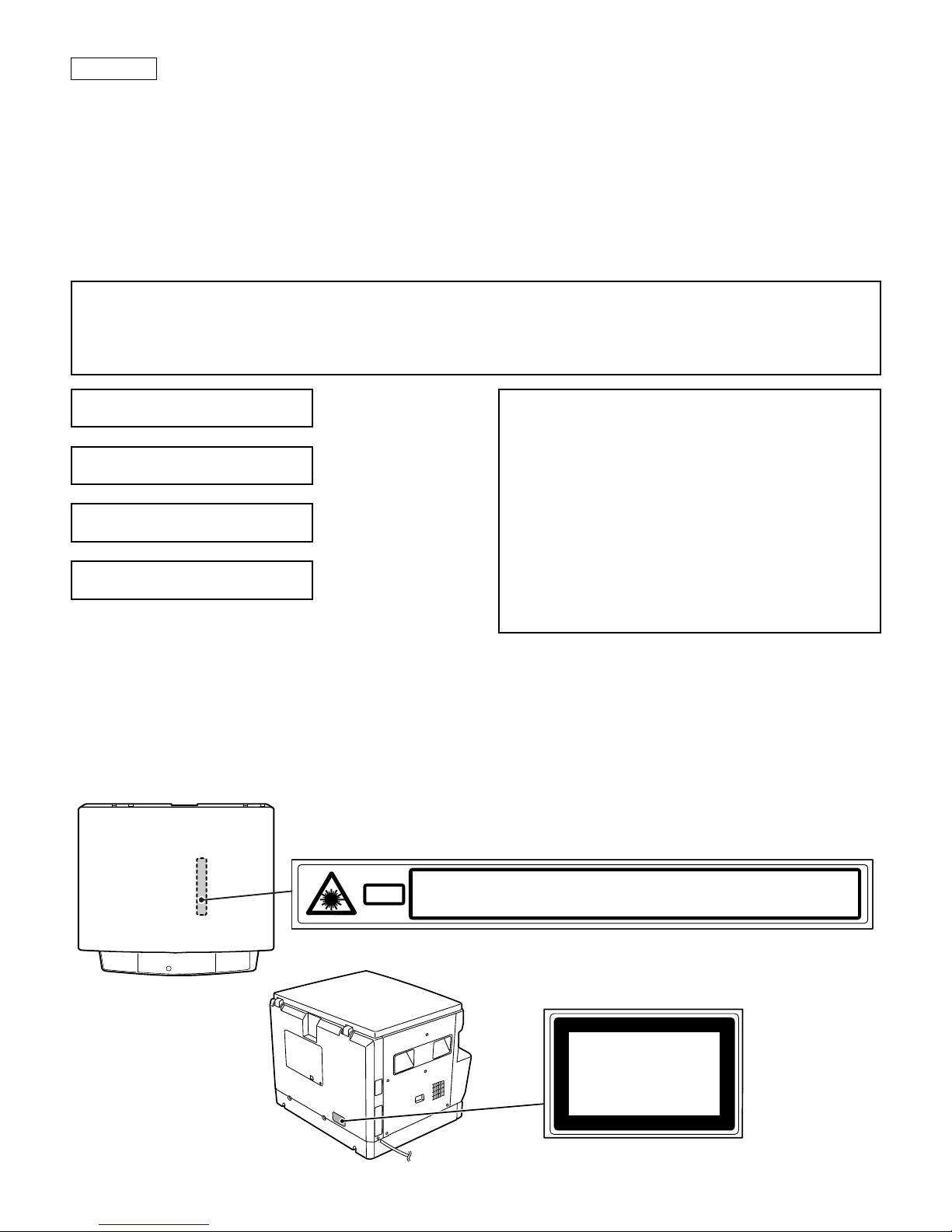
4) Do not disassemble the laser unit. Do not insert a screwdriver or
other reflecting material in the laser path. Reflected laser beam
can cause injury to your eyes.
5) When servicing with the machine operating, use great care not get
caught by chain, belt, gear, of other driving sections.
6) Do not leave the machine with the cabinet removed. If any other
person than the serviceman would touch the machine, he or she
could be injured by fire or electric shock.
7) Be careful to protect your eyes from toner, developing agent, and
ink. Be careful not to inhale them.
If toner, developing agent, or ink should enter your eyes, wash
them with water and consult a doctor if necessary.
8) There are some sharp edges in the machine. Be careful not to
injure your fingers when servicing.
9) Do not put toner or waste toner or a container with toner or waste
toner from the copier into a fire.
10)When replacing the lithium battery attached to the PWB, be sure
to use the one specified. If the specification of the battery is not
the one spcified, the battery may explode causing a breakdown or
malfunction of the machine.
11)When carrying a part of the unit with a PWB or an electronic part,
be sure to put it in an anti-static-electricity bag. Otherwise a break-
down or malfunction may occur.
C. Note for installation place
The machine performances depend on the environmental conditions
of the installation areas. Avoid installation in the following areas:
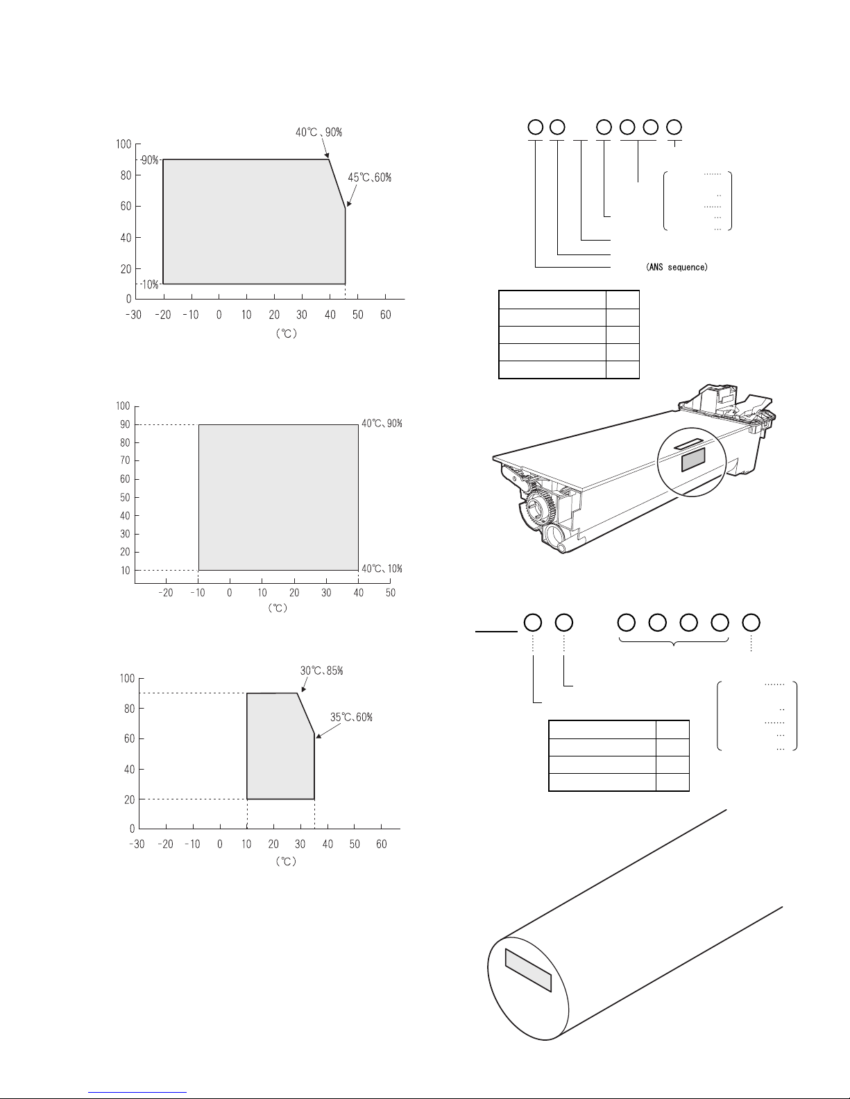
1) Avoid high temperature, high humidity, low temperature, low
humidity.
Avoid areas subject to a rapid change in temperature and
humidity.
If installed in such a place, paper may be dampened and conden-
sation may form inside the machine, causing paper jam or dirty
copy. For use and storage of the machine, refer to the specifica-
tions described below.
2) Avoid areas with excessive vibration. It may cause a breakdown
of the machine.
3) Avoid a poorly ventilated area.
This machine uses the static electricity copy process, ozone is
generated in the machine. The quantity of ozone generated is
designed to a harmless level. If, however, the machine is used
continuously in a poorly ventilated place, there may be a smell of
ozone. Therefore install the machine in a well-ventilated area.
4) Avoid area with direct sunlight.
Direct sunlight may deform plastic parts or discolor and spoil
toner, causing dirty copy or a breakdown of the machine.
5) Avoid area with ammonium or organic gases.
This machine which uses an organic photoconductor (OPC) drum,
the drum may be damaged by ammonium or organic gases.
Avoid installation near a diazo type copier. It may cause dirty copy
or a breakdown of the machine.
6) Avoid a dusty area.
If dust enters the machine, it may cause dirty copy or a break-
down of the machine.
7) Avoid installation near a wall.
Some machines have an exhaust and intake vent. If the exhaust
or intake is obstructed, it may cause dirty copy or a breakdown of
the machine.
8) Avoid installation on an unstable surface. The machine could drop
or tip over causing an injury or a breakdown of the machine. If the
paper feed desk or an option desk is available, it is advisable to
use it. When using an option desk, be sure to fix the adjusters on
the floor and lock the casters.
AR-162 [1] SPECIFICATIONS 11/21/2000
AR-162 GENERAL – 1

[2] SPECIFICATIONS
1. Copy mode
A. Type
Type Desk-top
B. Machine composition
AR-162 16-CPM standard model
AR-163 16-CPM standard model (with shifter)
AR-201 20-CPM standard model (with shifter)
AR-206 20-CPM duplex model (with shifter)
AR-207 20-CPM duplex model (with shifter, R-SPF, E-sort)
AR-F201 20-CPM (with FAX. SPF)
(1) Option
Machine Model
250 sheets paper feed unit AR-DE5
250 sheets ×2 paper feed
unit AR-DE6
SPF AR-SP2 AR-F201 standard
RSPF AR-RP1 AR-207 standard
Original cover AR-VR1
Electronic sorting kit AR-EB3 AR-207 standard
Printer expansion kit AR-PB8
Facsimile extension kit AR-FX2 AR-F201 standard
LCD panel kit
(20 digits ×2 lines) AR-PA1 AR-F201 standard
Job separator tray AR-TR2 AR-F201 standard
PS2 expantion kit AR-PS1
Extension memory for FAX
(2MB) AR-MM5
Extension memory for FAX
(4MB) AR-MM6
Extension memory for FAX
(8MB) AR-MM7
C. Copy speed
(1) Scan One Print many
AR-162 Not available
(Available for AR-163 for North America,
Australia, Asia)
AR-163
AR-201/F201 Available
AR-206/207
Condition: Copy speed in the normal copy from all the paper feed
ports including the manual paper feed port.
(2) Continuous copy speed (Sheets/min)
a. AR-162/163
Paper size Normal Enlargement
(200%) Reduction
(50%)
AB
system
A3 9 9 9
B4 10 10 10
A4 16 16 14
A4R 12 12 12
B5 16 16 16
B5R 14 14 14
Paper size Normal Enlargement
(200%) Reduction
(50%)
Inch
system
11" ×17" 9 9 9
8.5" ×14" 10 10 10
8.5" ×13" 11 11 11
8.5" ×11" 16 16 14
8.5" ×11"R 12 12 12
8.5" ×5.5" 16 16 16
b. AR-201/206/207/F201
Paper size Normal Enlargement
(200%) Reduction
(50%)
AB
system
A3 11 11 11
B4 12 12 12
A4 20 20 20
A4R 14 14 14
B5 20 20 20
B5R 16 16 16
Inch
system
11" ×17" 10 10 10
8.5" ×14" 12 12 12
8.5" ×13" 12 12 12
8.5" ×11" 20 20 20
8.5" ×11"R 15 15 15
8.5" ×5.5" 20 20 20
D. First copy time
(1) Basic speed
First copy time 7.2sec (A4, 8.5" ×11"/1st tray/with OC)
E. Document
Max. document size A3, 11" ×17"
Document reference
position Left side center
Detection (Platen) AR-162 None
AR-163
AR-201/F201 Available
AR-206/207
Detection size A3, B4, A4, A4R, B5, B5R, A5
11" ×17", 8.5" ×14",
8.5" ×13", 8.5" ×11",
8.5" ×11"R, 8.5" ×5.5" (8.5" ×13" is
detected by key input.)
(1) SPF/R-SPF
Standard/Option Option
SPF; AR-SP2 (AR-F201 standard)
RSPF; AR-RP1 (AR-206 only)
(AR-207 standard)
Document load capacity 30 sheets (56 ∼90g/m2equivalent)
(15 ∼23.9 lbs.)
Document size
(Max. ∼Min.) A3 ∼A5
11" ×17" ~ 8.5" ×5.5" (8.5" ×5.5",
duplex is inhibited.)
Document replacement
speed 16 sheets/min (A4 ×8.5" ×11"
normal copy)
Document set/Paper feed
direction Face up, Center reference, Paper
feed from the top
Document weight 56 ∼90g/m2, 15 ∼23.9 lbs
Document size detection On the document feed tray
Document mixture Copy mode: Not Available
AR-162 [2] SPECIFICATIONS 11/21/2000
AR-162 SPECIFICATIONS – 1

F. Paper feed
Copy size
(Max. ∼Min.) (A3 ∼A6) 11" ×17" ∼8.5" ×5.5"
Paper feed
system AR-162 1 cassette + Multi manual paper
feed
AR-163
AR-201/F201 2 cassette + Multi manual paper
feed
AR-206/207
Paper feed
capacity AR-162 50 ×1 (Paper feed tray) + 100
(Multi bypass feed tray)
AR-163
AR-201/F201 250 ×2 (Paper feed tray) + 100
(Multi bypass feed tray)
AR-206/207
Remaining
quantity
detection
Cassette section Empty detection available,
size detection by key input
Manual tray Only empty detection
available
(1) Paper feed section of the copier
Paper feed size A3, B4, A4, A4R, B5, B5R, A5
11" ×17", 8.5" ×14", 8.5" ×13", 8.5" ×11",
8.5" ×11"R, 8.5" ×5.5" (For A5 and 8.5" ×
5.5", only No. 1 tray available.)
Side front Front
Paper feed
capacity 250 sheets (56 ∼80g/m2equivalent) (15 ∼21
lbs.)
Detection Paper empty detection available,
size detection (by key input)
Weight 56 ∼80g/m2(15 lbs. ∼21 lbs.)
Special paper Recycled paper
(2) Manual paper feed section
Paper feed size A3 ∼A6, 11" ×17" ∼8.5" ×5.5"
Paper feed
capacity 100 sheets
Detection Size detection not available, paper empty
detection available
Weight 56 ∼128g/m2(15 ∼34 lbs.)
Special paper Recycled paper, OHP film, labels
Paper feed Single except for recycled paper
(3) Option paper feed unit
1-step paper feed
unit 2-step paper feed
unit
Model AR-DE5 AR-DE6
Paper feed size A3, B4, A4, A4R, B5, B5R
11" ×17", 8.5" ×14", 8.5" ×13", 8.5" ×11",
8.5" ×11"R
Capacity
(56 ∼80g/m2)About 250 sheets ×
1 step About 250 sheets ×
2 steps
Paper weight 56 ∼80 g/m2
(15 ∼21 lbs.)
Moisture preserving
heater None
Detection Paper empty detection, size detection
(by key input)
Paper size setting User setting (by key input)
External dimensions
(W ×D ×H) 590 ×471 ×88mm 590 ×471 ×
173.5mm
Weight About 5kg About 10kg
Special paper Recycled paper
Power Supplied from the machine
G. Job speed
S-S (1st step) 100% (document replacement rate)
(AR-162/163)
80% (document replacement rate)
(AR-201/206/207/F201)
Condition: With SPF
H. Multi copy
Max. number of multi copy 99 sheets
I. Warmup time
Warmup time Approx. 35 sec ∗
Pre-heat Available
*May vary depending on the surrounding temperature.
J. Copy magnification ratio
Fixed magnification ratio AB system: 50, 70, 81, 86, 100, 115,
122, 141, 200%
Inch system: 50, 64, 77, 95, 100, 121,
129, 141, 200%
Zooming 50 ∼200%
Independent
zooming/vertical Available (50 ∼200%)
Independent zooming
(horizontal) Available (50 ∼200%)
K. Print density
Density mode Auto/Manual/Photo
No. of manual adjustment 5 steps (Manual/Photo)
Toner save mode Set by the user program
L. Void width
Void area Lead edge 1 ∼4mm, rear edge 4mm or less
(Duplex 4mm or less), both sides 4mm or less
Image loss Max. 4mm in total of lead edge and rear
edge, max. 4mm in total of right and left
edges (Normal copy)
M. Auto duplex
Standard/Option Standard provision (AR-206/207 only) (D →
D/D →S enable only when RSPF is installed)
Not available for AR-162/163/201/F201
N. Paper exit/finishing
Paper exit
section capacity Face down 250 sheets
Job separator Job separator, option (AR-TR2)
(AR-F201 standard)
Upper: FAX/Printer, Lower: Copier
Upper: 100sheets, Lower 150sheets
Full detection Available (Job separator upper step)
Finishing Electronic sort board: Option (AR-EB3)
(AR-207 standard)
Electronic sort
capacity A4 (8.5" ×11") standard document 60 sheets
Offset function AR-162 None
AR-163 Available (by the shifter)
AR-201/F201
AR-206/207
Staple function None
AR-162 [2] SPECIFICATIONS 11/21/2000
AR-162 SPECIFICATIONS – 2

(1) Electronic sort board (Option AR-207 standard)
Electronic sort Sorting 60 sheets of A4 standard
documents
Grouping 60 sheets of A4 standard
documents
Rotation copy If there is paper of same size as the
document, the image is rotated to copy even
though the paper is set in the different
direction from the document direction.
2 in 1, 4 in 1 Copies of 2 pages or 4 pages are integrated
into one surface. Divided by solid lines,
(Selectable by the user program.)
Edge erase Images surrounding the document are erased
when copying. (Adjustable in 0 ∼20mm by the
user program.)
Center erase The image at the center is erased when
copying. (Adjustable in 0 ∼20mm by the user
program.)
Margin shift Binding margin is made at the left edge of the
set documents.
O. Additional functions
APS*(APS not available by flowing in
during use of SPF/RSPF)
AMS*(AMS not available by flowing in
during use of SPF/RSPF)
Duplex ✕AR-206/207 only available
Document count ✕
Sorter When the electronic sort board
installed.
Independent
zooming Vertical/Horizontal: 50 ∼200%
1 set 2 copy Enlargement inhibited, inhibited
during the use of SPF
Binding margin Shift width 9mm
Edge erase Width 5mm (Adjustable 0 ∼20mm)
Black-white
reversion Whole surface only
2 in 1, 4 in 1
Rotation copy
Memory copy ✕(AR-201/206/207/F201 and AR-163
for North America, Australia, Asia:
Available)
Pre-heat function Conditions set by the user program
Auto power shut
off function Conditions set by the user program
Auto tray
switching
Message display (FAX/Printerextension)
(AR-F201 standard)
User program
Total counter
: Available
✕: Not available
∗: By the document size set key
: When an option is installed
P. Other specifications
Photoconductor type OPC (Organic Photo Conductor)
Photoconductor drum dia. 30mm
Copy lamp Xenon lamp
Developing system Dry 2-component magnetic brush
development
Charging system Saw teeth charging
Transfer system (+) DC corotron
Separation system (–) DC corotron
Fusing system Heat roller
Cleaning system Contact blade
Q. Package form
Body Body/Accessaries
R. External view
External dimensions
(W ×D ×H) 590 ×531 ×470 mm (AR-162/163)
590 ×531 ×523mm (AR-201/206)
590 ×531 ×650mm (AR-207/F201)
Occupying area (W ×D) 590 ×531mm
(When the manual tray is installed.)
Weight About 32kg (AR-162/163)
About 35.7kg (AR-201)
About 36.2kg (AR-206)
About 43kg (AR-207)
S. Power source
Voltage AC120V, 220V, 230V, 240V ±15%
Frequency 50/60Hz common
T. Power consumption
Max. power consumption About 1.3KWh
*EnergyStar standard (The 2nd level conformity)
Pre-heat About 60Wh
Auto power shut
off 0wh ⋅
about 4.8wh (when FAX or the printer
expansion kit is installed)
U. Digital performance
Resolution Reading 400 dpi
Writing 600 dpi
Gradation Reading 256 gradations
Writing Binary
AR-162 [2] SPECIFICATIONS 11/21/2000
AR-162 SPECIFICATIONS – 3

[3] CONSUMABLE PARTS
1. Supply system table
A. USA/CANADA/Latin America
NO Name Content Life Model name Remark
1Toner cartridge (Black)
<With IC> Toner ×1
(Toner: Net Weight 475g)
Vinyl bag ×1 13K AR-201NT
(AR-201-J*1) Life setting by A4 6% document
<Not compatible with the
AR-160/200/225>
2Developer Developer ×1
(Developer: Net Weight 400g)
Vinyl bag ×1 30K AR-201ND <Not compatible with the
AR-160/200/225>
3Drum kit Drum ×1
Drum fixing plate ×1 30K AR-201DR The AR-201 DR/DM can be used
instead of the AR-200 MR/LR/CR.
*1: For USA government
B. Middle East/Africa
NO Name Content Life Model name Remark
1Toner cartridge (Black)
<With IC> Toner ×1
(Toner: Net Weight 475g)
Vinyl bag ×1 13K AR-201FT Life setting by A4 6% document
<Not compatible with the
AR-160/200/225>
2Developer Developer ×1
(Developer: Net Weight 400g)
Vinyl bag ×1 30K AR-201SD <Not compatible with the
AR-160/200/225>
3Drum kit Drum ×1
Drum fixing plate ×1 30K AR-201DR The AR-201 DR/DM can be used
instead of the AR-200 MR/LR/CR.
C. Europe/East Europe
NO Name Content Life Model name Remark
1Toner cartridge (Black)
<With IC> Toner ×1
(Toner: Net Weight 475g)
Vinyl bag ×1 13K AR-201T Life setting by A4 6% document
<Not compatible with the
AR-160/200/225>
2Developer Developer ×1
(Developer: Net Weight 400g)
Vinyl bag ×1 30K AR-201DV <Not compatible with the
AR-160/200/225>
3Drum kit Drum ×1
Drum fixing plate ×1 30K AR-201DM The AR-201 DR/DM can be used
instead of the AR-200 MR/LR/CR.
D. Asia
NO Name Content Life Model name Remark
1Toner cartridge (Black)
<With IC> Toner ×1
(Toner: Net Weight 475g)
Vinyl bag ×1 13K AR-201ST Life setting by A4 6% document
<Not compatible with the
AR-160/200/225>
2Developer Developer ×1
(Developer: Net Weight 400g)
Vinyl bag ×1 30K AR-201SD <Not compatible with the
AR-160/200/225>
3Drum kit Drum ×1
Drum fixing plate ×1 30K AR-201DR The AR-201 DR/DM can be used
instead of the AR-200 MR/LR/CR.
E. Hong Kong/China
NO Name Content Life Model name Remark
1Toner cartridge (Black)
<With IC> Toner ×1
(Toner: Net Weight 475g)
Vinyl bag ×1 13K AR-201ST-C Life setting by A4 6% document
<Not compatible with the
AR-160/200/225>
2Developer Developer ×1
(Developer: Net Weight 400g)
Vinyl bag ×1 30K AR-201SD-C <Not compatible with the
AR-160/200/225>
3Drum kit Drum ×1
Drum fixing plate ×1 30K AR-201DR-C The AR-201 DR/DM can be used
instead of the AR-200 MR/LR/CR.
AR-162 [3] CONSUMABLE PARTS 11/21/2000
AR-162 CONSUMABLE PARTS – 1

2. Environment conditions
A. Transportcondition
(1) Transportconditions
(2) Storage conditions (packed conditions)
B. Use conditions
C. Life (packed conditions)
Photoconductor drum (36 months from the production month)
Developer, toner (24 months from the production month)
3. Production number identification
<Toner cartridge>
The label on the toner cartridge shows the date of production.
∗: Destination
Division No.
Japan option 1
Ex option 2
Japan, same pack 6
Ex, same pack 7
<Drum cartridge>
The label on the drum cartridge shows the date of production.
Division No.
Ex production 1
Option 2
Same pack 3
Humidity (%)
Temperature
Use envi-
ronment
conditions
1
The end digit of production year
January
September
October
November
December
1
9
0
X
Y
Factory
Serial number (for each
month) (00001-99999) Production
month
~
~
Ver. A
Temperature
Humidity (%)
Temperature
Humidity (%)
The end digit of production year
Ver.No.
January
September
October
November
December
1
9
0
X
Y
Indicates production in China.
Production
day.
Production
month.
Destination
(∗)
~
~
B
AR-162 [3] CONSUMABLE PARTS 11/21/2000
AR-162 CONSUMABLE PARTS – 2

[4] EXTERNAL VIEWS AND INTERNAL STRUCTURES
1. Appearance
1 Document feeder cover 2 Original table 3 Handles
4 Power switch 5 Operation panel 6 Paper output tray
7 Front cover 8 Paper trays 9 Side cover
10 Side cover handle 11 Bypass tray guides 12 Bypass tray
13 Bypass tray extension 14 Charger cleaner
∗The AR-162/163 are equipped with one paper tray.
2. Internal
1 Document feeder tray 2 Original guides 3 Feeding roller cover
4 Exit area 5 Reversing tray 6 Toner cartridge lock release lever
7 Toner cartridge 8 Photoconductive drum 9 Roller rotating knob
10 Fusing unit release levers 11 Right side cover 12 Paper guide
1
2
3
4
5
8
7
610
9
3
11
12
13
14
Reversing single pass feeder (RSPF)
123
45
6
7
910
11
12
8
AR-162 [4] EXTERNAL VIEWS AND INTERNAL STRUCTURES 11/21/2000
AR-162 EXTERNAL VIEWS AND INTERNAL STRUCTURES – 1

3. Operation Section
1 INTERRUPT key and indicator 2 Copy quantity display 3 ZOOM indicator
4 Copy ratio display key 5 Zoom keys 6 PAPER SIZE ENTER key
7 AUDIT CLEAR key 8 PAPER SIZE indicators 9 Alarm indicators ∗2
10 POWER SAVE indicator 11 SPF/RSPFindicator 12 Output tray full indicator
13 B/W REVERSE key and indicator 14 XY-ZOOM key and indicator 15 SORT/GROUP key and indicators
16 ORIGINAL DATA indicator 17 2 IN 1 / 4 IN 1 key and indicators 18 AUTO/MANUAL/PHOTO key and
indicators
19 Light and dark keys and indicators ∗3 20 Numeric keys 21 Zero key ∗4
22 CLEAR key 23 START key and indicator 24 CLEAR ALL key
25 PRESET RATIO selector keys and
indicators 26 ORIGINAL SIZE ENTER key and
indicators 27 AUTO PAPER SELECT indicator
28 TRAY SELECT key 29 AUTO IMAGE key and indicator 30 Paper feed location/misfeed location
indicators
31 DUAL PAGE COPY key and indicator 32 ERASE key and indicators 33 MARGIN SHIFT key and indicator
34 ORIGINAL TO COPY key and indicators
∗1
ON: Indicates that the machine is in the energy saving (pre-heat)
mode.
Blink: Indicates that the machine is in the process of resetting from
the energy saving mode or just after supplying the power.
(During warmup)
OFF: Indicates that resetting from the energy saving mode is com-
pleted and that the fusing temperature is in ready state.
The combinations of the above display lamps are as follows:
( = ON, = OFF)
Lamp Immediatelyafter
power ON Ready Copying
Pre-heatlamp Blink
Ready lamp
Other lamps
Lamp Energy
saving mode
(Pre-heating)
Energy
saving mode
(Autopower
shut off)
Resetting
from energy
saving mode
Copy is
startedduring
resettingfrom
energysaving
mode
Pre-heatlamp Blink Blink
Ready lamp
Other lamps
∗2 Maintenance indicator
When the set count number (set by the simulation) is reached,
the lamp lights up. The machine does not stop.
Toner cartridge replacement required indicator
When toner density is lower than a specified level, the TONER
CARTRIDGE REPLACEMENT indicator lights up to warn the
user.
If toner is not added after approximately 10% is copied, the
indicator starts blinking and machine starts to supply toner.
(Toner cartridge replacement indicator keeps lighting up)
If toner density is not back to specific level after two minutes, the
READ indicator goes out and Toner indicator starts blinking, and
the copier stops.
Developer replacement required indicator
(1) Lights up when the developer counter reaches 30K.
(2) Selection between STOP and NON-STOP is allowed with the
service simulation No.
(Default: NON-STOP)
Paper required indicator
Misfeed indicator
∗3 Light key
Press and hold this key for 5 sec, and the machine will enter the
user program mode.
∗4 Zero key
Press and hold this key, and the total output counter value is
displayed on the copy quantity display.
Not used for the copier features.
1234567891011121314151617
18 19 20 22 23 24 25 26 27 28 29 30 31 32 343321
AR-162 [4] EXTERNAL VIEWS AND INTERNAL STRUCTURES 11/21/2000
AR-162 EXTERNAL VIEWS AND INTERNAL STRUCTURES – 2

4. Motor, solenoid, clutch
No. Name Code Function, operation
1 Exhaust fan motor VFM Cools the inside of the machine.
2 Shifter motor SHTM Shifts the paper exit tray. (Except for the AR-162)
3 Toner motor TM Toner supply
4 Mirror motor MRM Drives the optical mirror base (scanner unit).
5 Duplex motor DPX Switchback operation and paper exit motor in duplex. (only
AR-206/207)
6 Cooling fan motor CFM Cools the inside of the machine.
7 Main motor MM Drives the machine.
8 Paper feed solenoid CPFS1 Solenoid for paper feed from cassette
9 Resist roller solenoid RRS Resist roller rotation control solenoid
10 Manual paper feed clutch MPFC Drives the manual paper feed roller.
11 Manual paper feed solenoid MPFS Manual paper feed solenoid
12 Manual paper transport clutch MPTC Drives the manual paper transport roller.
13 2nd tray transport clutch CPFC2 Drives the 2nd tray transport roller.
14 2nd tray transport solenoid FSOL2 2nd tray transport solenoid
15 1st tray transport solenoid FSOL1 1st tray transport solenoid
16 2nd tray paper feed solenoid PSOL2 2nd tray transport solenoid
17 Paper feed clutch CPFC2 Drives the cassette paper feed roller.
18 1st tray paper feed solenoid PSOL1 1st tray transport solenoid
19 1st tray paper feed clutch CPFC1 Drives the 1st tray transport roller.
20 PS clutch RRC Drives the resist roller
1
24
3
9
8
10
7
6
11
12
5
13
14
15
16
17
18
19
20
AR-162 [4] EXTERNAL VIEWS AND INTERNAL STRUCTURES 11/21/2000
AR-162 EXTERNAL VIEWS AND INTERNAL STRUCTURES – 3

5. Sensor, switch
No. Name Code Function, operation
1 Mirror home position sensor MHPS Detects the mirror (scanner unit) home position.
2 Document size sensor DSIN Paper size detection
3 Toner density sensor TCS Toner quantity detection
4 Paper exit sensor (paper exit side) POD1 Detects paper exit.
5 OC open/close sensor DOC COVER Detects open/close of OC/SPF.
6 Right door switch DSWR Side door open/close detection
7 Paper full sensor P FULL Paper exit tray section full detection <For JOB separator>
8 Lift sensor LFTHP Paper feed tray lift up detection <For JOB separator>
9 Lower limit sensor JTRAY Job separator tray lower limit detection
10 Paper exit sensor (DUP side) PDPX Paper transport detection
11 Shifter home position sensor SFTHP Shifter home position detection (Excluding AR-162)
12 Thermistor RTH Fusing section temperature detection
13 Thermostat Fusing section abnormally high temperature detection
14 1st tray detection switch 1st tray detection
15 Paper in PIN Paper transport detection
16 2nd tray detection switch 2nd tray detection (Excluding AR-162/163)
17 Manual sensor MPED Manual transport detection
18 2nd tray door open/close sensor DRS2 2nd tray door open/close detection (Excluding AR-162/163)
19 2nd tray paper entry sensor PPD2 Paper transport detection (Excluding AR-162/163)
20 1st tray paper empty sensor CSS1 1st tray paper empty detection
21 2nd tray paper empty sensor CSS2 2nd tray paper empty detection (Excluding AR-162/163)
22 Power switch MAIN SW Turns ON/OFF the main power source.
123 6
5
4
7
8
9
10
11
13
14
12
15
16
17
18
19
20
22
21
AR-162 [4] EXTERNAL VIEWS AND INTERNAL STRUCTURES 11/21/2000
AR-162 EXTERNAL VIEWS AND INTERNAL STRUCTURES – 4

6. PWB unit
No. Name Function, operation
1 Copy lamp Inverter PWB Copy lamp control
2 FAX main PWB Fax communication control <AR-F201 or Option>
3 TEL/LIUPWB Line control (Fax communication) <AR-F201 or Option>
4 Printer control PWB Printer control <Option>
5 Network Board Network system interface <Option>
6 CCD sensor PWB Image scanning
7 Mother PWB Connecting the MCU and Printer/FAX PWB <AR-F201 or Option>
8 Main PWB (MCU) Machine control/Image process
9 Paper exit interface PWB Paper exit, finishing control
10 Electronic sort PWB Electronic sort function control <AR-207 or Option>
11 Tray interface PWB Paper tray control
12 High voltage PWB High voltage control
13 Operation main PWB Operation panel input/Display, operation panel section control
14 Power PWB AC power input/DC power control
15 LCD PWB Printer and FAX status display <AR-F201 or Option>
16 Fax operation PWB Operation for FAX <AR-F201 or Option>
17 CRUM PWB Saving toner cartridge data
124
39
8
10
7
6
11
12
5
13
14
15
16
17
AR-162 [4] EXTERNAL VIEWS AND INTERNAL STRUCTURES 11/21/2000
AR-162 EXTERNAL VIEWS AND INTERNAL STRUCTURES – 5

7. Cross sectional view
No. Name Function/Operation
1 Copy lamp Image radiation lamp
2 Copy lamp unit Operates in synchronization with No. 2/3 mirror unit to radiate documents sequentially.
3 LSU unit Converts image signals into laser beams to write on the drum.
4 Lens unit Reads images with the lens and the CCD.
5 MC holder unit Supplies negative charges evenly on the drum.
6 Paper exit roller Used to discharge paper.
7 Transport roller Used to transport paper.
8 Upper heat roller Fuses toner on paper (with the teflon roller).
9 Lower heat roller Fuses toner on paper (with the silicon rubber roller).
10 Waste toner transport roller Transports waste toner to the waste toner box.
11 Drum unit Forms images.
12 Transfer charger unit Transfer images (on the drum) onto paper.
13 Duplex transport roller Transports paper for duplex (only AR-206/207).
14 Resist roller Takes synchronization between the paper lead edge and the image lead edge.
15 Manual paper feed tray Manual paper feed tray
16 Manual paper feed roller Picks up paper in manual paper feed.
17 No. 2/3 mirror unit Reflects the images from the copy lamp unit to the lens unit.
18 Manual transport roller Transports paper from the manual paper feed port.
19 2nd tray paper transport roller Transports paper from the 2nd tray. (Excluding AR-162/163)
20 2nd tray paper feed roller
(semi-circularroller) Picks up paper from the 2nd tray. (Excluding AR-162/163)
21 1st tray paper feed roller
(semi-circularroller) Picks up paper from the 1st tray.
22 MG roller Puts toner on the OPC drum.
12 3 45
6
7
8
9
10
11
12
15
14
16
17
13
1819202122
AR-162 [4] EXTERNAL VIEWS AND INTERNAL STRUCTURES 11/21/2000
AR-162 EXTERNAL VIEWS AND INTERNAL STRUCTURES – 6

[5] UNPACKING AND
INSTALLATION
1. Installing conditions
1) Copierinstallation
Do not install your copier in areas that are:
•damp, humid, or very dusty
•exposed to direct sunlight
•poorly ventilated
•subject to extreme temperature or humidity changes, e.g., near an
air conditioner or heater.
•Be sure to allow the required space around the machine for servic-
ing and proper ventilation.
2) Power source
•Use an exclusive-use power outlet. If the power plug of this
machine is inserted into a power outlet commonly used with other
illumination units, flickers of the lamp may be result. Use a power
outlet which is not used commonly with any illumination units.
•Avoid complex wiring.
3) Grounding wire connection.
•To avoid danger, be sure to connect a grounding wire. If no
grounding wire is connected and a leakage occurs, a fire or an
electric shock may be result.
2. Removal of protective material and
fixing screw
1) Remove all tapes and protective material.
•Remove all tapes, then open the document cover and remove
the protective material of sheet shape
2) Remove the fixing screw.
•Use a coin to remove the fixing screw.
•The fixing screw is required when transporting the machine.
Keep it in the tray. (Refer to the later description.)
3. Installing procedure
A. Developer cartridge installation
1) Open the manual tray, and open the side cover.
2) Open the front cover.
•Hold the both sides and pull down to open.
3) Loosen the screw and remove the developer cartridge.
4) Remove the developer tank from the developer cartridge.
5) Supply developer into the developer tank while rotating the MG
roller.
*Shake the developer bag enough before opening it.
4" (10 cm)
AR-162 [5] UNPACKING AND INSTALLATION 10/5/2000
AR-162 UNPACKING AND INSTALLATION – 1

6) Attach the developer tank to the developer cartridge.
*After supplying developer into the developer cartridge, do not
tilt or shake the developer cartridge.
7) Attach the developer cartridge to the copier, and fix it with the
screw.
B. Toner cartridge installation
1) Shake the toner cartridge several times horizontally, and remove
the tape.
*Do not hold the shutter lever when shaking.
*After removing the tape, do not tilt or shake the toner cartridge.
2) Attach the toner cartridge to the copier.
3) Pull the shutter lever.
Close the front cover A, then close the side cover B.
•When closing the front cover, gently press the both sides.
•When closing the side cover, hold the knob.
•When closing the covers, be sure to close the front cover first,
then close the side cover. If closed in a wrong sequence, the
covers may be broken.
4. Removal and storage of fixing screw
1) Lift the knob and gently pull out the tray.
2) Hold the paper pressure plate and turn the fixing screw in the
arrow direction.
3) Store the fixing pin and the fixing screw in the tray.
•Store the fixing screw which was removed in the above proce-
dure 2 and the fixing screw which was removed in procedure 2
of 2.
•Removal of protective material and fixing screw in the storage
place in the tray.
A
B
Pressure
plate
lock
Screw
Tape
Shutter
4 or 5 times
AR-162 [5] UNPACKING AND INSTALLATION 10/5/2000
AR-162 UNPACKING AND INSTALLATION – 2

5. Changing the copy paper size in the tray
1) Gently lift and pull out the paper tray until it stops.
2) Push the pressure plate down until it locks in place.
3) Squeeze the lock lever of the front guide and slide the front guide
to match the width of the paper.
4) Move the left guide to the appropriate slot as marked on the tray.
•When using 11" ×17" copy paper, store the left guide in the slot
at the left front of the paper tray.
5) Load copy paper into the tray.
6) Place the paper size plate in the front of the paper tray.
•The paper size indication which shows through the slot on the
front of the copier should match the selected paper size.
7) Push the paper tray firmly back into the copier.
8) To set the selected paper size, press and hold down the PAPER
SIZE ENTER key. The selected paper feed location indicator and
the corresponding paper size (which has been set) indicator will
blink. All other indicators will go out.
•For paper size setting, ensure that the COPY mode has been
selected. However, if printer or facsimile output is being per-
formed, paper size setting cannot be made even in the COPY
mode.
9) Use the TRAY SELECT key to select the paper tray of which the
paper size has been changed.
•Each time the TRAY SELECT key is pressed, a paper tray is
indicated with a blinking paper feed location indicator. If an
optional paper feed unit is not installed, this operation is not
needed.
10) Use the ORIGINAL SIZE ENTER key to select the paper size
which is set.
•Each time the ORIGINAL SIZE ENTER key is pressed, a
paper size will be indicated with a blinking paper size in-
dicator.
11) Press the START key and then the PAPER SIZE ENTER key.
•To change the paper size setting of another tray, repeat steps
9 to 10 after pressing the START key.
Left guide
Front guide
AR-162 [5] UNPACKING AND INSTALLATION 10/5/2000
AR-162 UNPACKING AND INSTALLATION – 3

[6] ADJUSTMENTS
1. Adjustment item list
Section Adjustment item Adjustment procedure/SIM No.
A Process
section
(1) Developing doctor gap adjustment Developing doctor gap adjustment
(2) MG roller main pole position adjustment MG roller main pole position adjustment
(3) Developing bias voltage output adjustment
(4) Main charger voltage output adjustment
B Mechanism
section
(1) Image lead edge position adjustment SIM 50-1
(2) Main scanning direction (FR direction) distortion
balance adjustment
No. 2/3 mirror base unit installing position adjustment
Copy lamp unit installing position adjustment
(3) Main scanning direction (FR direction) distortion
adjustment
Rail height adjustment
(4) Sub scanning direction (scanning direction) distortion
adjustment
Winding pulley position adjustment
(5) Main scanning direction (FR direction) magnification
ratio adjustment
SIM 48-1
(6) Sub scanning direction (scanning direction)
magnification ratio adjustment
a OC mode in copying (SIM 48-2)
b SPF mode in copying (SIM 48-5)
c OC mode in FAX (SIM 48-6)
d SPF mode in FAX (SIM 48-7)
(7) Off center adjustment a OC mode (SIM 50-13)
b SPF mode (SIM 50-16)
(8) OC (SPF) open/close detection position adjustment OC (SPF) open/close detection position adjustment
(9) Document size detection sensor SIM 41-3
C Image density
adjustment
(1) Copy mode SIM 46-1
2. Copier adjustment
A. Process section
(1) Developing doctor gap adjustment
1) Loosen the developing doctor fixing screw A.
2) Insert a thickness gauge of 1.5mm to the three positions at 20mm
and 130mm from the both ends of the developing doctor as
shown.
3) Push the developing doctor in the arrow direction, and tighten the
developing doctor fixing screw. (Perform the same procedure for
the front and the rear frames.)
4) Check the clearance of the developing doctor. If it is within the
specified range, then fix the doctor fixing screw with screw lock.
*When inserting a thickness gauge, be careful not to scratch the
developing doctor and the MG roller.
<Adjustment specification>
Developing doctor gap
Both ends (20mm from the both ends): 1.5−0.15
+0.1 mm
C (Center)(150mm from the both ends): 1.55−0.2
+0.15mm
(2) MG roller main pole position adjustment
1) Remove and separate the waste toner box and put the developing
unit on a flat surface.
2) Tie a string to a needle or a pin.
3) Hold the string and bring the needle close to the MG roller
horizontally. (Do not use paper clip, which is too heavy to make a
correct adjustment.) (Put the developing unit horizontally for this
adjustment.)
4) Do not bring the needle into contact with the MG roller, but bring it
to a position 2 or 3mm apart from the MG roller. Mark the point on
the MG roller which is on the extension line from the needle tip.
5) Measure the distance from the marking position to the top of the
doctor plate of the developing unit to insure that it is 18mm.
If the distance is not within the specified range, loosen the fixing
screw A of the main pole adjustment plate, and move the adjust-
ment plate in the arrow direction to adjust.
AR-162 [6] ADJUSTMENT 11/1/2000
AR-162 ADJUSTMENTS – 1

(3) Developing bias voltage adjustment
Note: •Use a digital multi-meter with an internal resistance of
10MΩor more.
1) Set the digital multi-meter range to DC700V.
2) Put the test rod of the digital multi-meter on the developing bias
voltage output check pin.
3) Turn on the power.
4) Adjust the adjustment volume VR31 so that the output voltage is
within the specified range shown below.
<Adjustment specification>
Mode Specification
Developing bias voltage DC-400±8V VR31
(4) Grid bias voltage adjustment
Note: •Use a digital multi-meter with an internal resistance of
10MΩor more.
1) Set the digital multi-meter range to DC700V.
2) Put the test rod of the digital multi-meter on the grid bias voltage
output check pin.
3) Turn on the power.
4) Adjust the adjustment volumes (VR51, VR52) so that the output
voltage is within the specified range. (The voltage is outputted in
the grid bias high output mode during warming up, and in the grid
bias low output mode after completion of warming up.)
<Adjustment specification>
Mode Specification
Grid bias LOW DC-400±20V VR52
Grid bias HIGH DC-525±10V VR51
B. Mechanism section
(1) Image lead edge position adjustment (SIM 50-1)
a. OC image lead edge position adjustment
Note: In advance to this adjustment, the sub scanning magnification
ratio adjustment must be performed.
1) Set a scale on the OC table as shown below.
2) Make a copy.
3) Check the copy output. If necessary, perform the following adjust-
ment procedures.
4) Execute SIM 50-1.
5) Set the OC lead edge position set value (Exposure display
<AUTO> ON) to “99.”
The OC image scanning start position is shifted inside the docu-
ment edge.
6) Set the main cassette lead edge void adjustment value (Exposure
display <PHOTO> ON) * to “1.”
The lead edge void becomes the minimum.
7) Set the print start position value (Exposure display <EXP1> ON)
to “99”and make a copy.
The print start position is shifted inside the document edge.
8) Measure the image loss R of the copied image. Enter the set
value of the image scanning lead edge position (Exposure display
<AUTO> ON) again.
•1 step of the set value corresponds to about 0.127mm shift.
•Calculate the set value from the formula below.
99 - R/0.127 (mm) = Image loss set value <R: Image loss meas-
urement value (mm)>
Example: 99 - 4/0.127 = 99 - 31.5 = about 67
Note: If the set value is not obtained from the above formula,
perform the fine adjustment.
5
10
5mm
4mm
*The dimension varies depending on the model.
10
5mm
0mm
5
*The scanning edge is set.
(A line may be printed by scanning the document edge.)
AR-162 [6] ADJUSTMENT 11/1/2000
AR-162 ADJUSTMENTS –2
Other manuals for AR-162
2
This manual suits for next models
5
Table of contents
Other Sharp Copier manuals

Sharp
Sharp AR-800 imager User manual

Sharp
Sharp AR-162 User manual

Sharp
Sharp AR-RP7 User manual

Sharp
Sharp AR-156 User manual

Sharp
Sharp AL-1550 User manual

Sharp
Sharp DX-C310 Operation User manual

Sharp
Sharp Z-810 User manual

Sharp
Sharp AR-5132 User manual

Sharp
Sharp AL-2020 Setup guide

Sharp
Sharp AR-C240P User manual

Sharp
Sharp MX-2300G User manual

Sharp
Sharp AR-M208 User manual

Sharp
Sharp AR-F152 User manual

Sharp
Sharp AR-M201 Setup guide

Sharp
Sharp SF-2220 User manual

Sharp
Sharp AR-C150 User manual

Sharp
Sharp AR-5415 User manual

Sharp
Sharp SF-2218 User manual

Sharp
Sharp AR-C260 Programming manual

Sharp
Sharp AR-FX8 User manual