Sharp AR-RP3 User manual

Digital Copier
Reverse Single Pass
Feeder (RSPF)
MODEL AR-RP3
[ 1 ] PRODUCT OUTLINE..............................................................................1
[ 2 ] SPECIFICATIONS ..................................................................................1
[ 3 ] UNPACKING AND INSTALLATION........................................................1
[ 4 ] EXTERNAL VIEW AND INTERNAL STRUCTURE.................................4
[ 5 ] OPEREATIONAL DESCRIPTIONS ........................................................5
[ 6 ] ADJUSTMENTS......................................................................................6
[ 7 ] DISASSEMBLY AND ASSEMBLY..........................................................9
[ 8 ] MAINTENANCE....................................................................................14
[ 9 ] ELECTRICAL SECTION.......................................................................15
CONTENTS
Parts marked with " " are important for maintaining the safety of the set. Be sure to replace these parts with specified
ones for maintaining the safety and performance of the set.
SHARP CORPORATION This document has been published to be used
for after sales service only.
The contents are subject to change without notice.
SERVICE MANUAL

[1] PRODUCT OUTLINE
This machine is a duplex document auto feeder attached to a digital
copier.
It feeds originals automatically to allow continuous copying.
[2] SPECIFICATIONS
Document set
direction Face up
Document set
position Center reference
Document transport
system Sheet through type
Document feed
sequence Top take-up feed
Document size AB series: A3 ~ A5
Inch series: 11 x 17 ~ 8.5 x 5.5
Duplex invoice not available
Document weight 56 ~ 90g/m2, 15 ~ 23.9lbs
Document set
quantity Max. 30 sheets (90g/m2, max. thickness
4mm)
Dimensions 583mm (W) x 435mm (D) x 133mm (H)
Weight About 5.5 kg
Power source Supplied from the copier. (DC 24V)
Power consumption 26.4W
Document size
detection On the document feed tray
Detection size Japan: A3, B4, A4, A4R, B5, B5R,
A5 (A5R for FAX only)
Inch series: 11 x 17, 8.5 x 14, 8.5 x 11,
8.5 x 11R, 8.5 x 5.5
EX AB series: A3, B4, A4, A4R,
A5 (A5R for FAX only)
Mixture of different
document sizes Mixture paper feed : Not available during
copying. Available during FAX (same width
only)
Random paper feed Not available
Document reverse Not allowed
Display section (LED) None
Document exchange
speed S ®S 23 sheets/min
S ®S 27 sheets/min
[3] UNPACKING AND INSTALLATION
1. Unpacking
For unpacking, refer to the figure below.

2. Installation
Parts included
Turn off the main switch of the copier and then remove the power plug
of the copier from the outlet.
1. Remove the platen cover.
Lift the platen cover and remove it from the copier.
2. Remove the screws of the glass holders.
Remove the two screws (M3 x 8) of the left glass holder and the three
screws (M3 x 8) of the right glass holder.
3. Remove the front cabinet.
While raising the front cabinet toward your side, remove the three
pawls from the rear side of the front cabinet.
4. Remove the glass holders (right and left) and remove
the document glass.
Remove the right and left glass holders and remove the document
glass.
5. Attach the front cabinet.
Attach the front cabinet of the copier.
At this time, ensure that the three pawls on the rear side are securely
inserted to the frame of the copier.
6. Attach the RSPF glass holder.
Insert the RSPF glass holder to the document glass.
Then, attach the document glass to the copier, fix the left glass holder
that has been removed in step 3 using two screws (M3 x 8), and fix
the RSPF glass using three screws (M3 x 8).
RSPF glass cover
Intermediate tray
(only for AR-RP3/DM-RP1)
Screws (M3 x 8)
Screws (M3 x 8)
Pawls
Left glass holder
Document glass Right glass holder
Pawls
Screws (M3 x 8)
Screws (M3 x 8)
Document glass
RSPF glass holder

7. Attach the RSPF.
Insert the hinge portion of the RSPF to the mounting portion of the
copier by holding the RSPF at an angle toward the rear side.
8. Connect the relay connector.
Connect the Centronics connector of the RSPF to the connector of the
copier and then tighten the screws of the connector.
9. Remove the filament tape.
Remove the filament tape located in the positions shown in the illus-
tration.
10. Attach the intermediate tray.
Insert the intermediate tray all the way into the RSPF.
Insert the power plug of the copier to the outlet and turn on the main
switch of the copier.
11. Adjust the RSPF white correction pixel
Open the RSPF and execute SIM 63-7 to adjust the RSPF auto white
correction pixel.
12. Check the copy magnification ratio.
Set an original on the document glass and copy it.
Then, set an original in the document feeder tray and copy it.
If the magnification ratio of the copy from the RSPF is different from
that of the copy from the document glass, carry out adjustment refer-
ring to the service manual.
13. Check the center displacement.
Set an original on the document glass and copy it.
Then, set an original in the document feeder tray and copy it.
If the center of the copy image from the RSPF is different from that of
the copy image from the document glass, carry out adjustment refer-
ring to the service manual.
14. Check the top end position.
Set an original on the document glass and copy it.
Then, set an original in the document feeder tray and copy it.
If the top end position of the copy image from the RSPF is different
from that of the copy image from the document glass, carry out adjust-
ment referring to the service manual.
15. Check the open/close detection position.
If the open/close detection position measured with the open/close
detection position adjustment method described in the service manual
does not conform to the specifications, carry out adjustment referring
to the service manual.
Installation of RSPF is now complete.
Hinge
Screw
Screw
Filament tape
Intermediate tray

[4] EXTERNAL VIEW AND INTERNAL STRUCTURE
1. External view
No. Name
1 Document set tray
2 Document guide
3 Document feed section cover
4 Document transport section cover
5 Document exit section
2. Internal structure
Sensor, detector, etc.
No. Code Name Type Function/Operation
1 W0 Document set sensor Photo transmission Detects presence of documents.
2 COVER Open/close sensor Photo transmission Detects open/close of the paper feed unit.
3 W1 Document width sensor (A4R, LTR, A5) Photo transmission Detects the document width on the tray.
4 W2 Document width sensor (B4, B5) Photo transmission Detects the document width on the tray.
5 W3 Document width sensor (WL, TR, A5R, A4, LT) Photo transmission Detects the document width on the tray.
6 PSOL Pickup solenoid — —
7 PAPER Paper entry sensor Photo transmission Detects presence of documents.
8 RSOL Pressure release solenoid — —
9 CLH Transport clutch — —
10 MOT SPF motor Stepping motor Drives document feed on the tray, transport, and
paper exit roller.
11 GSOL Gate solenoid — —
12 — Interface PWB — —
13 L1 Document length detection SW (Short) Photo transmission Detects the document length on the tray.
14 L2 Document length detection SW (Long) Photo transmission Detects the document length on the tray.
15 COVER OPEN Book sensor Photo transmission Detects the SPF float.
16 PO Paper exit sensor Photo transmission Detects presence of documents.
12
3
4
5
12
3
4
5
6
7
9
8
10
11
12
13
14
15 16

[5] OPEREATIONAL DESCRIPTIONS
1. Major parts of the paper fed section
No. Part name Operation
1 Document length
sensor (L2) Detects the document length on
the tray.
2 Document length
sensor (L1) Detects the document length on
the tray.
3 Document set sensor
(W0) Detects presence of documents.
4 Document width sensor
(W1, W2, W3) Detects the document width.
5 Pickup roller Picks up documents.
6 Paper feed roller Feeds and transports documents.
7 Paper entry sensor
(PAPER) Detects transport of documents.
8 PS roller Makes synchronization between
the document lead edge and the
image lead edge.
9 PS follower roller Makes synchronization between
the document lead edge and the
image lead edge.
10 Transport roller Transports documents.
11 Transport follower roller Transports documents.
12 Paper exit sensor (PO) Detects transport of documents.
13 Paper exit follower roller Discharges documents.
14 Paper exit roller Discharges documents.
15 Reverse gate Opens/closes the document
reverse path.
16 Paper exit gate Separate document exit to the
intermediate or the paper exit tray.
17 Intermediate tray Discharges documents to the
intermediate tray during document
reverse.
2. Out line of operations
[Duplex documents]
1) Document set (Document set sensor ON)
¯
2) Document size detection (Document width sensors W1, W2, W3
detect the document width, and document length sensors L1, L2
detect the document length.)
¯
3) Copier COPY key ON
¯
4) SPF motor ON
¯
5) Pickup solenoid ON
¯
6) Pickup roller and paper feed roller rotation
¯
7) Paper entry sensor detects the document presence.
¯
8) PS roller rotation
¯
9) Copying (Front surface of document)
¯
10) Transport roller rotation
¯
11) Paper exit roller rotation
¯
12) Paper exit gate falls down. (Documents are discharged to the
intermediate tray.)
¯
13) Reverse gate falls down.
¯
14) Paper exit roller reverse rotation (Documents are fed to the re-
verse path.)
¯
15) Paper entry sensor detects document presence.
¯
16) PS roller rotation
¯
17) Copying (Back surface of document)
¯
18) Transport roller rotation
¯
19) Paper exit roller rotation
¯
20) Paper exit gate falls down (Documents are discharged to the
intermediate tray.)
¯
21) Reverse gate falls down.
¯
22) Paper exit roller reverse rotation (Documents are fed to the re-
verse path.)
¯
23) Paper entry sensor detects document presence.
¯
24) PS roller rotation
¯
25) Paper exit roller rotation
¯
26) Paper exit gate lifts up.
¯
27) Documents are fed to the paper exit tray.
¯
28) Next document ®(YES) ®Go to 4).
¯ (NO)
29) SPF motor OFF
1 2 3,4 5 6 7 8
910111314 151617 12

3. Document size detection
1) Document size detection with the document set tray
When documents are set on the document set tray in the auto selec-
tion mode of paper/copy magnification ratio, the document size is
detected and paper and the copy magnification ratio are automatically
selected. When different sizes of documents are set, the max. size is
detected. The document width is detected by the document width
sensors (W1, W2, W3), and the document length is detected by the
document length sensors (L1, L2) to identify the document size.
Judgement of the document size is made in a certain timing after
detecting the document with the document set sensor (W0).
Document set
size and set
direction
Document width sensor Document
length sensor
W1 W2 W3 L1 L2
AB
series
A5
B5
A5R
A4
B5R
A4R
8.5 x 13"
B4
A3
Inch
series
8.5" x 5.5"
8.5" x 5.5"R
11" x 8.5"
11" x 8.5"R
8.5" x 13"
8.5" x 14"
11" x 17"
(Note) Detection sensor ON: , OFF:
[6] ADJUSTMENTS
(1) SPF auto white correction pixel adjustment
[Function]
The SPF white correction start pixel position is automatically adjusted.
This adjustment is performed after the lens unit is replaced.
(2) RSPF magnification ratio adjustment
Note: When performing this adjustment, check that the CCD unit
is properly installed.
: When performing this adjustment, check that the OC mode
adjustment in copying is completed.
1) Place a scale on the document table as shown below, and make a
normal copy to make a test chart.
2) Set the test chart to the SPF and make a normal copy.
3) Compare the copy and the test chart.
If an adjustment is needed, perform the following procedures.
4) Execute SIM 8-1. The auto exposure lamp lights up.
Sim63-7 SPF ADJ.
WHITE ADJUST
PRESS OK KEY EXEC
Sim63-7 SPF ADJ.
WHITE ADJUST
EXEC
Sim63-7 SPF ADJ.
WHITE ADJUST
CPMPLETE
[160]
PRESS OK KEY EXEC
Sim63-7 SPF ADJ.
WHITE ADJUST
ERROR
[ 0]
PRESS OK KEY EXEC
Press
the [OK] key. Press
the [RETURN] key.
[Operation]
(Initial screen)
(During execution)
(Initial screen with the execution result displayed)
Normal end Abnormal end
During execution,
"EXEC" is highlighted.
Open the SPF unit and press the [OK] key.
[ ] indicates the order number of the pixel of the white
sheet for SPF exposure correction in the SPF position.
When the adjustment is completed normally,
"COMPLETE" is displayed, and data are written into the
EEPROM.
When the adjustment is completed abnormally,
"ERROR" is displayed and data are not written into the
EEPROM.
The SPF white correction start pixel = Displayed
pixel position - 34
If the simulation is executed with the SPF unit
closed, an error is resulted.
[CA] key: Cancels the test command.
[Interruption] key: Shifts to the sub code entry menu.
[OK] key: Shifts to the execution menu.
Interruption is inhibited during execution.
Note: Since the printed paper is used as the test chart,
place the scale in parallel to both sides.

5) The current correction value is displayed on the display section in
two digits.
6) Enter the set value, and press the START key.
The entered correction value is stored and a copy is made.
7) Change the duplex document mode to the simplex document
mode.
The MANUAL lamp lights up, and the current correction value of
the back surface sub scanning direction magnification ratio is dis-
played on the display section in two digits.
8) Enter the set value, and press the SATART key.
The entered correction value is stored and a copy is made.
<Adjustment specifications>
Mode Spec SIM Set value Set range
Magnification ratio adjustment Normal: ±1.0% SIM 48-1
4: SPF surface magnification ratio adjustment
5: SPF back magnification ratio adjustment
Add 1: 0.1% increase
Reduce 1: 0.1% decrease 1 ~ 99
(3) RSPF document off center adjustment
Note: When performing this adjustment, check that the paper off-
center is properly adjusted.
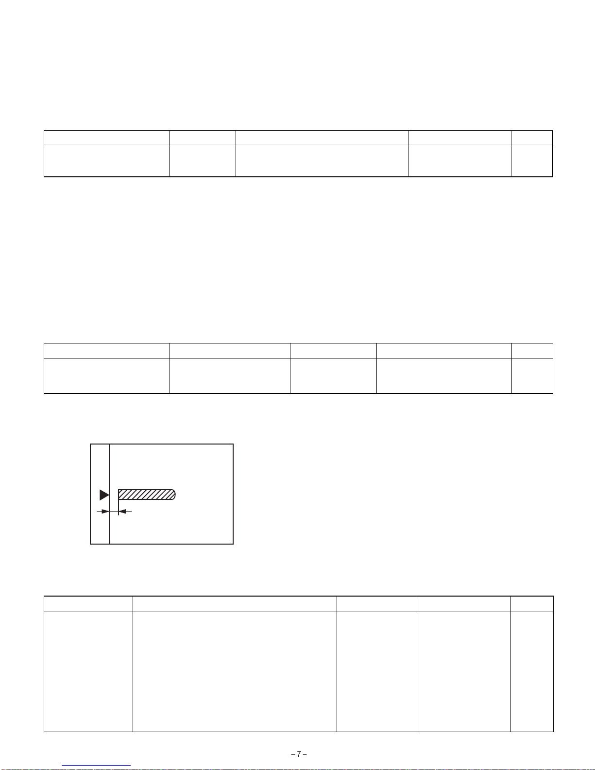
1) Set the center position adjustment test chart (made by yourself) on
the RSPF.
<Adjustment specifications>
Draw a line in the center of paper. (In the scanning direction)
2) Make a normal copy from the manual feed tray, and compare the
copy and the test chart.
If an adjustment is required, perform the following procedures.
3) Execute SIM 50-12.
4) The current off-center adjustment value is displayed on the display
section in two digits.
5) Enter the set value and press the START key.
The entered correction value is started and a copy is made.
<Adjustment specifications>
Mode Specification SIM Set value Set range
Document off-center (RSPF
mode) Simplex: Center ±3.0mm
Duplex: Center ±3.5mm SIM 50-12
2: SPF surface
3: SPF back
Add 1: 0.1mm shifted to R side.
Reduce 1: 0.1mm shifted to L side. 1 ~ 99
(4) RSPF image lead edge position adjustment
1) Set a scale on the OC table as shown below. 2) Make a copy, and use the copied paper as the document and
make a copy from RSPF again.
3) Check the copied paper. If an adjustment is required, perform the
following procedures.
4) Execute SIM 50-6.
5) Set the SPF lead edge position set value (Exposure display
<MANUAL> ON) so that the image similar to the adjusted image at
the OC image lead edge position described previously is printed.
<Adjustment specifications>
Adjustment mode SIM Set value Specification Set range
RSPF image lead edge
position SIM 50-6
1: Surface document scan start position adjustment value
2: Back document scan start position adjustment value
3: Rear edge void adjustment value (SPF)
4: Surface image loss set value
5: Back image loss set value
6: Surface rear edge image loss set value
7: Back rear edge image loss set value
8: RRC cancel adjustment value (Back of the machine)
9: memory reverse position adjustment value
10: Duplex left edge void adjustment value
1step: 0.127mm shift Lead edge void: 1 ~ 4mm
Image loss: 3mm or less 1 ~ 99
Note: Since the printed paper is used as the test chart,
place the scale in parallel to both sides.

(5) RSPF open/close detection position adjustment
(SIM 41-4)
1) Execute SIM 41-4.
2) Gradually close the RSPF from the full open position, and measure
distance A when the display on the operation panel changes. (See
the figure below.)
Distance A = Table glass top - RSPF handle rib
<Spec value>
SPF open/close position A: 125 - 225mm
3) If the distance is outside the specified range, adjust the open/close
sensor attachment plate position as shown below.
·Distance < 125mm: Shift toward A.
·Distance > 225mm: Shift toward B.
(6) RSPF white correction pixel position
adjustment (required in an RSPF model when
replacing the lens unit)
1) Fully open the SPF.
2) Execute SIM 63-2.
3) When the operation panel displays "COMPLETE," the adjustment
is completed.
4) If the operation panel displays "ERROR," perform the following
measures.
·When the display is 0: Check that the SPF is open.
Check that the lamp is ON. (If the lamp is OFF, check the MCU
con-nector.) Check that the CCD harness is properly inserted into
the MCU con-nector.
·When the display is 281 or above:
1) Remove the table glass.
2) Remove the dark box.
3) Slide the lens unit toward the front side and attach it, then
exe-cute SIM.
·When the display is 143 or below:
1) Remove the table glass.
2) Remove the dark box.
3) Slide the lens unit toward the rear side and attach it, then
execute SIM.
·After sliding the lens unit, perform the OC main scan magnification-
ratio automatic adjustment (SIM 48-1-1) and the RSPF original
off-center adjustment.
·This adjustment is basically O.K. with SIM 63-2.
Sim41-4 20˚ SENSOR
OCSW
1[128]200 2[128]200
3[128]200 4[128]200
5[128]200
A
5
R
F

[7] DISASSEMBLY AND ASSEMBLY
1. External fitting section
(Note) Turn the paw in the arrow direction.
2. Paper feed unit section
1) Paper feed unit
2) Document transport section cover
3) Document feed section cover
4) Sensor PWB
1
2
2
3
12
1
2
3
2
1
1
1
3
2
2
4

5) Pickup solenoid
(Note) Remove section A of the pickup solenoid from the solenoid
arm groove.
6) Clutch gear ass’y
7) Pickup roller ass’y
(Note) When assembling the pickup roller ass’y 4, check that rib A is
on the rib of the solenoid arm.
8) Pick up roller, paper feed roller
A
1
2
1
5
2
4
3
6
6
2.5~4.0
From Edge pawl
1
4
2
3
A
1
2
3
1
1
4

3. Interface PWB
4. Document tray section
1) Document tray
2) Rack cover
3) Document length sensor SW
5. Drive frame section
1) Book sensor
2
1
1
1
2
1
3
2
1
34
3
4
2
1
12

2) Drive frame unit
3) Drive frame ass’y and drive belt
4) Pressure release solenoid
5) SPF motor
6. Transport section
1) Clutch
(Note) When assembling, check that the rib is in the clutch groove A
and fix it with E-ring.
1
2
1
1
1
2
3
4
3
2
1
1
2
4
3
2
A
1

2) Transport roller gear
3) Reverse gate
4) Transport roller
5) PS roller
6) Paper feed paper guide lower
(Note) When assembling, check that the paper feed paper guide
lower is securely set to rib A and boss B.
7) Paper feed paper guide upper
1
1
1
1
2
3
1
1
1
2
1
1
1
1
1
2
BA
1
2

8) Paper exit roller
9) Gate solenoid
(Note) When assembling, check that the paper exit gate hook is set in
the solenoid groove.
When assembling, the bearing D-cut surface shuold be faced
down.
[8] MAINTENANCE
1. Maintenance parts
No. Name Work item Service call Remark
1 Pickup roller Cleaning
2-1 Separation unit Cleaning Replace when
worn down.
2-2 Front separation sheet Cleaning
3 Paper feed roller Cleaning
4 PS roller Cleaning
5 Transport roller Cleaning
6 Paper exit roller Cleaning
(Note) When performing maintenance, refer to [7] DISASSEMBLY
AND ASSEMBLY.
2
1
1
1
Bearing
1
3
4
5
6
2-1
2-2

87 6 5 4 32 1
A
B
C
D
1
234
5
678
D
C
B
A
SPF/RSPF INTERFACE PWB
SPFOPEN
/PSOL
/RSOL
/CLH
L2
L1
PAPER
MOTOR
DRIVER
24V
5V
SEL(A#,B#,C#)
YSPF
/GSOL
SPF(CLH,PSOL,RSOL,GSOL)
PDOWNA
PDOWNB
PAPER
/SPFCOVER
SPFOPEN
/SPFOUT
/SPFOUT
/SPFCOVER
W0
W1
W2
W3
SPF SENSOR PWB
24V
24V
24V
24V
24V
24V
5V
5V
5V
5V
24V
SENSOR
SOL/CLU
RSPF ONLY
MOTOR
(A,B,/A,/B)
TRANSISTOR
ARRAY
DATA
SELECTOR
LEOPARD
(OPTION INTERFACE
PWB)
SPF(MODA,MODB,
/MODA,/MODB)
[9] ELECTRICAL SECTION
1. Block diagram

8 7 6 5 4 32 1
A
B
C
D
12345678
D
C
B
A
SPFPSOL
CN3
B7B-PH-K-S
B20B-PHDSS BL
OR
PL
BR
LB
GY
PK
PHDR-20 BL
PL
BR
LB
PK
OR
PHR-7
SPFPSOL
24V1
1
2
2
1
BL
RD
PHNR-2-H
L1
SGND
11
/PSOL 6
15
2
24V1
16
5V
45V
CN1
B3B-PH-K-R(RD)
GY
OR
PHR-3(RD)
3
SPF0PEN2
SGND
5V
1
CN4
B2B-PH-K-S PHR-2
2/GSOL
24V1 1
3
N.C.2
24V1
/CLH
1
CN7
B3B-PH-K-S
BL BL
SPFCLH
3
/SPFOUT2
SGND
5V
1
GY
OR
CN2
B3B-PH-K-K(BK)
GY
OR
CN5
B26B-PHDSS
12
13
-
18
25
20
16
3
7
6
17
15
10
23
8
14
11
22
19
4
9
21
5
24
1
2
24V
/SPFMODA
SPFOPEN
/SPFOUT
PDOWNA
PAPER
N.C.
SGND
SGND
YSPF
/SPFCOVER
PDOWNB
SPFCLH
/SPFMODB
SPFPSOL
PGND
24V
SPFMODB
SELA#
SELB#
5V
SPFRSOL
SELC#
SPFGSOL
PGND
SPFMODA
9
10
8
12
11
24V
/SPFMODA
SPFOPEN
/SPFOUT
PDOWNA
3
PAPER
2
N.C.
6
SGND
5
SGND
7
YSPF
4
/SPFCOVER
1
21
22
20
24
23
15
14
18
17
19
16
13
25
26
PDOWNB
SPFCLH
/SPFMODB
SPFPSOL
PGND
24V
SPFMODB
SELA#
SELB#
5V
SPFRSOL
SELC#
SPFGSOL
PGND
SPFMODA
1
2
3
1
2
3
PHR-7
7
1
20
3
14
9
5
SPFCOVER
SGND
W2
5V
W0
W1
W3
W0
5v
SPFCOVER
W3
W2
W1
1
2
6
5
4
3
SGND7
GY
L1
SGND
2
3
5
4
5V 16
SGND 61
L2 52
5V 43
SPFRSOL
SPFRSOL
24V1
1
2
1
2
LB
RD
SMP-02V-BC(JST)
SMR-02V-N(JST)
3
2
1
3
2
1
5V
W1
2
3
6
5
W0 17
SGND 71
SPFCOVER 62
W3 53
W2 44
2
1
3
L2 13
17SGND
/RSOL 10
1224V1
18SGND
pull up 8
19PAPER
PHNR-7-HPHNR-7-H
BU7P-TR-P-H
PHNR-2-H
BU2P-TR-P-H
BU6P-TR-P-H
PHNR-6-HPHNR-6-H
PHR-3
DF3-3S-2C
DF3-3S-2C
DF3-3S-2C
DF3-3S-2C
SPFGSOL
OR
LB
GY
OR
GY
BL
BL
OR
PL
BR
LB
GY
PK
BL
OR
PL
BR
LB
GY
PK
BL
RD
OR
LB
GY
OR
GY
BL
OR
LB
GY
OR
GY
BL
OR
LB
GY
OR
GY
BL
GY
BR
PL
SPFOPEN
/SPFOUT
PHR-3(BK)
PAPER
L2
L1
LB
RD
BL
LB
PK
PL
RD
RD
BL
LB
PK
PL
RD
RD
PHR-6
3/B
2/A
5N.C.
4B
1A
724V1
624V1
PLUSE MOTOR
3
/B
2
/A
5
4B
1
A
24V1
6
24V1
DSPF ONLY
ORIGINAL TRAY
PAPER FEED UNIT
GY
BR
PL
GR
GY
OR
GR
PHR-3
BL
BL
BRBR
FG
FG
SRA-21T-4
26
SRA-21T-4SRA-21T-4 EARTH PLATE(SPF ONLY)
2. Actual wiring diagram
Option Interface PWB Interface PWB
Sensor PWB
(Paper Entry Sensor)
(Paper Exit Sensor)
(Book Sensor)
CN6

8 7 6 5 4 32 1
A
B
C
D
12345678
D
C
B
A
C114
0.047u/50V C115
0.047u/50V
IC2
TD62003AP
1B
2B
3B
4B
5B
6B
7B
GND
1C
2C
3C
4C
5C
6C
7C
COM
24V1
(A4) CN1-17
(A4) CN1-21
(A4) CN1-19
(A4) CN1-15
SPFCLH
SPFPSOL
SPFRSOL
SPFGSOL
/CLH
/RSOL
/GSOL
/PSOL CN2-6 (B3)
CN6-3 (B2)
CN2-10 (B3)
CN3-3 (A2)
Document size senser
(A3) CN2-9
(A3) CN2-3
(A3) CN2-5
(A3) CN2-7
(A3) CN2-15
(A3) CN2-13
W0
W2
W3
W1
L2
L1
R116
10K R117
10K R114
10K R115
10K R112
10K R113
10K R111
10K
5V
C125 C123
C126 C124 C122
C121
1000pF/50V*7
Senser Mtorix
SELC
H
L
L
L
L
H
H
H
SELB
L
L
L
L
H
H
H
H
SELA
L
H
L
H
L
H
L
H
L2
W3
W2
L1
Y
W1
SPF(H)/DSPF(L)
W0
/SPFDTC (L)
JP1
DSPF
/SPFDTC
74HC151
D0
D1
D2
D3
D4
D5
D6
D7
A
B
C
G
W
Y
VCC
GND
IC101
5V
C120
0.1u/25V ZD102
UDZ5.6
ZD104
UDZ5.6
ZD101
UDZ5.6
ZD103
UDZ5.6 C119
1000p/50V
C117
1000p/50V
C118
1000p/50V
SELA#
SELC#
SELB# CN1-5 (A4)
CN1-7 (A4)
CN1-3 (A4)
YSPF CN1-11 (A4)
CN7-4 (B2)
CN7-3 (A2)
CN7-2 (B3)
CN7-1 (B3)
CN7-6,7 (B3)
B
A
/B
/A
24V1
C103
0.047u/50V
C104
0.047u/50V
C1
47u/35V
IC1
CrA
CrB
VsA
RsA
VrefA
VrefB
RsB
VsB
In /A
In A
In /B
In B
Vmm
OUT /A
OUT A
OUT /B
OUT B
PG
LG
NC
NC
NC
NC
NC
NC
PG
PG
MTD1361
(C4) CN1-16
(C4) CN1-6
(C4) CN1-18
(C4) CN1-4 /SPFMODB
/SPFMODA
SPFMODA
SPFMODB
R2 1.5(1W)
C112
0.1uF/25V
C111
3300pF/50V
R1 1.5(1W)
R105
1KJ
R104
1KJ
C108
0.1uF/25V
C110
3300pF/50V
C107
2200pF/50V R101
7.5KJ C113
2200pF/
50V
R107
7.5KJ
5V
R102 2.4k
R106 2.4k
R103
620F
TP103
$PIN0
1
R108
390F R109
430F
TP101
$PIN0
TP102
$PIN0
PDOWNA
PDOWNB
10k 10k
10k
10k
(C4) CN1-20
(C4) CN1-22
Q101
DTC114EK
Q102
DTC114EK
R110
110F
C109
0.1u/25V
C2
10u/16V
3. Circuit Diagram Interface PWB (1/2)
Pattern width: 1.0mm or above
Pattern width: 0.5mm or above

8 7 6 5 4 32 1
A
B
C
D
12345678
D
C
B
A
/SPFOUT
SPFPSOL
SELA#
SPFGSOL
SFPRSOL SPFMODA
SPFCLH
SPFMODB
SPFOPEN
PDOWNA
PDOWNB
/SPFMODB
SELB#
SELC#
YSPF
/SPFCOVERPAPER
/SPFMODA
W3
PAPER
L2
/PSOL
W1
W2
W0
/RSOL
/SPFCOVER
L1
/SPFOUT /CLH
/GSOL SPFOPEN
A/
A
/B
B
5V CN4-2 (B2)
(C1)
(D4)
(D4)
CN2-19 (A3)
(E3)
5V
(C1)
(C1)
(B1)
CN2-20 (B3)
24V1
(D4)
(B1)
(B2) CN5-2
(E3)
(E3)
(E3)
(D4)
(C1)
(B3)
CN1-2 (C4)
(E4)
(B3)
(B3)
(B3)
CN1-1 (A4)
(D4)
(B3)
(B3)
(E4)
CN1-14 (C4)
CN1-12 (C4)
(E4)
(E4)
(E4)
(E4)
(E4)
24V1
5V
24V1
5V 5V
24V1
24V1
5V
C105
0.047u
C116
0.1u/25V
+
C3
10u/16V F1
ICP-N38
C106
0.047u
CN5
B26B-PHDSS
1
3
5
7
9
11
13
15
17
19
21
23
25
2
4
6
8
10
12
14
16
18
20
22
24
26
CN6
B20B-PHDSS
1
3
5
7
9
11
13
15
17
19
2
4
6
8
10
12
14
16
18
20
C127
0.1u/25V
CN2
B3B-PH-K-E(BL)
1
2
3
CN1
1
2
3
CN4
B2B-PH-K-S
1
2
CN7
B3B-PH-K-S
1
2
3
C102
0.1u/25V
C101
0.1u/25V
CN3
B7B-PH-K-S
1
2
3
4
5
6
7
R119
470
R118
470
B3B-PH-K-R(RD)
3. Circuit Diagram Interface PWB (2/2)

Table of contents
Other Sharp Copier manuals

Sharp
Sharp AR-5415 User manual

Sharp
Sharp AR-205 User manual

Sharp
Sharp AL-1043 User manual

Sharp
Sharp AR-800 imager User manual

Sharp
Sharp AL-1000 Series User manual

Sharp
Sharp AL-2050 Setup guide

Sharp
Sharp AR-162 User manual

Sharp
Sharp AR-120E User manual

Sharp
Sharp AR-5520 User manual

Sharp
Sharp AR-507 User manual

Sharp
Sharp AR-C262M Key User manual

Sharp
Sharp SF-2314 User manual

Sharp
Sharp AR-C160 Manual

Sharp
Sharp SF-755 User manual

Sharp
Sharp AR-C150 User manual

Sharp
Sharp AR-C250 User manual

Sharp
Sharp AR-5015 User manual

Sharp
Sharp 00ZSF1116/A1E User manual

Sharp
Sharp IMAGER AR-5316 User manual

Sharp
Sharp AL-1611 User manual