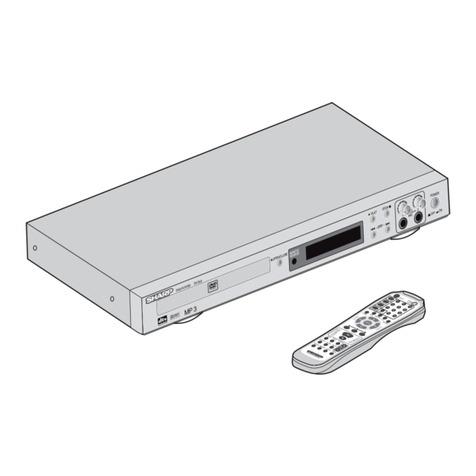
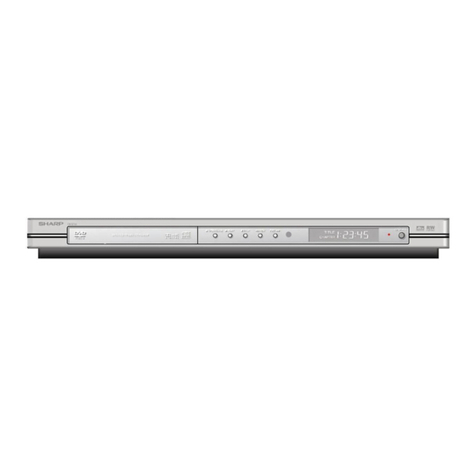
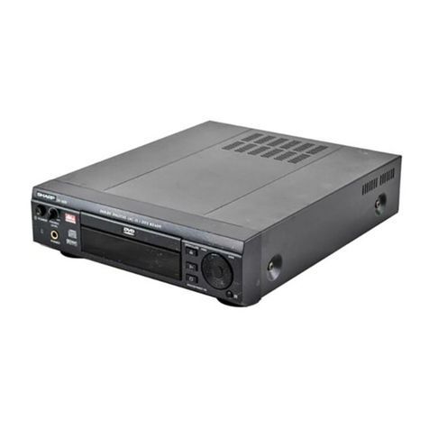
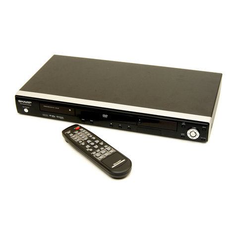
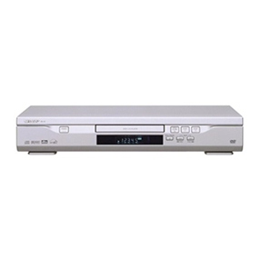
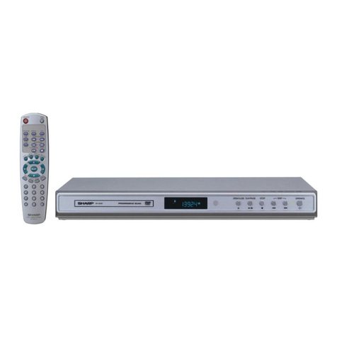
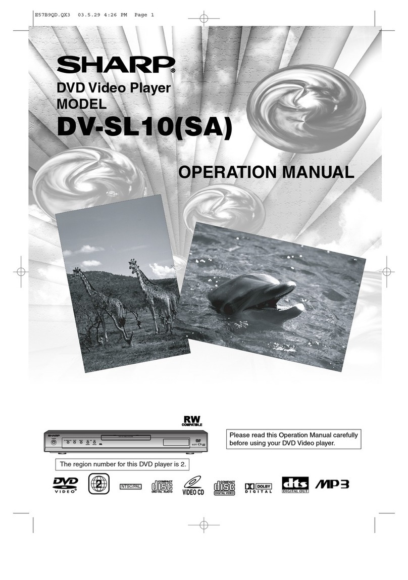
Sharp DV-740/T User manual

1
DV-740/X/W/T
S81Z3DV-740XX
SERVICE MANUAL
MODEL
Page
1. IMPORTANT SAFEGUARDS AND PRECAUTIONS ........................................................................... 2
2. FEATURES ........................................................................................................................................ 3
3. SPECIFICATIONS .............................................................................................................................. 3
4. PART NAMES ................................................................................................................................... 4
5. REMOTE CONTROL UNIT ................................................................................................................. 6
6. EXTENSION CABLE USE POINT (FOUR PLACES) ........................................................................... 7
7. SERVICE (TROUBLE SHOOTING FLOW CHART) ............................................................................. 8
8. NORMAL WAVEFORM ................................................................................................................... 11
9. IC FUNCTION LIST ........................................................................................................................... 19
10. BLOCK CIRCUIT SCHEMATIC DIAGRAMS ..................................................................................... 30
11. MAINBOARD ................................................................................................................................... 50
12. DISPLAY/OPTION BOARD .............................................................................................................. 56
13. POWER BOARD ............................................................................................................................. 58
14. PWB COMPONENT LIST ................................................................................................................ 60
15. REPLACEMENT PARTS LIST/EXPLODED VIEWS ......................................................................... 64
16. PACKING OF THE SET ................................................................................................................... 65
17. LOADER SET ................................................................................................................................. 67
CONTENTS
In the interests of user-safety (Required by safety regulations
in some countries) the set should be restored to its original
condition and only parts identical to those specified be used.
SERVICE MANUAL DVD VIDEO PLAYER MODELS DV-720S/720S(K)/720H
DVD VIDEO PLAYER
SHARP CORPORATION
DV-740/T
DV-740X/W
TENTATIVE

DV-740/X/W/T
2
1. IMPORTANT SAFEGUARDS AND PRECAUTIONS
Power Lead Protection
To avoid any malfunctions of the unit, and to protect
against electric shock, fire or personal injury, please
observe the following,
Hold the plug firmly when connecting or
disconnecting the AC power lead.
Keep the AC power lead away from heating
appliances.
Never put any heavy object on the AC power lead.
Do not attempt to repair or reconstruct the AC
power lead in any way.
Note:
This unit can be used only where the power
supply is AC 100V-240V, 50/60Hz. It cannot
be used elsewhere.
CAUTION:
USE OF CONTROLS OR ADJUSTMENTS OR
PERFORMANCE OF PROCEDURES OTHER
THAN THOSE SPECIFIED HEREIN MAY
RESULT IN HAZARDOUS RADIATION
EXPOSURE.
AS THE LASER BEAM USED IN THIS PLAYER
IS HARMFUL TO THE EYES, DO NOT
ATTEMPT TO DISASSEMBLE THE CABINET.
REFER SERVICING TO QUALIFIED
PERSONNEL ONLY.
WARNING:
TO REDUCE THE RISK OF FIRE OR
ELECTRIC SHOCK, DO NOT EXPOSE THIS
EQUIPMENT TO RAIN OR MOISTURE.
TO REDUCE THE RISK OF FIRE OR
ELECTRIC SHOCK, AND ANNOYING
INTERFERENCE, USE THE RECOMMENDED
ACCESSORIES ONLY.
Laser Diode Properties
Material: AlGalnP
Wave length: 635 nm
Emission Duration: Continuous
Laser output: Max. 0.5 mW
This player is classified as a CLASS 1 LASER product.
The CLASS 1 LASER PRODUCT label is located on
the rear cover.
This product contains a low power laser device. To
ensure continued safety do not remove any cover or
attempt to gain access to the inside of the product.
Refer all servicing to qualified personnel.
CLASS 1
LASER PRODUCT
(Rear of product)
3
DVD LOADER
Model No: SL-101H
Rating: 5V==0.6A 12V==1.2A
CLASS 1 LASER PRODUCT
“Complies with FDA radiation performance
standards, 21 CFR Subchapter J”
DANGER-
VISIBLE AND INVISIBLE LASER RADIATION
WHEN OPEN, AVOID DIRECT EXPOSURE TO
BEAM.
3
DV-740/X/W/T
•Playback of DVD, VIDEO CD, and Audio CD
•Dolby Digital*2, DTS*3, MPEG Audio digital out
*1Manufactured under license from Dolby Laboratories. "Dolby" and the double-D symbol ( ) are trademarks of Dolby
Laboratories.
*2"DTS" and "DTS Digital Surround" are trademarks of Digital Theater Systems, Inc.
2. FEATURES
3. SPECIFICATIONS
Specifications are subject to change without notice.
Weight and dimensions are approximate.
Digital Output (Linear PCM)
The digital output format (optical or coaxial) used in this Player is linear PCM audio sampled at 44.1 kHz or 48 kHz.
Linear PCM sound for DVD video discs sampled at 96 kHz cannot be output digitally.
Check the disc jacket for information on the audio sampling used.
TYPE SPECIFICATION
Power Supply type Switch Mode Power Supply
Input Voltage AC100V~240V(Auto Voltage Swithcing)
Mains Frequency 50/60Hz
Standby Power Consumption Less than 5W
Power Rating Less than 20W
Signal System NTSC/PAL
Disc compatibility DVD,VCD,VCD2.0,SVCD,CD-DA,MP3,
CD-R,CD-RW
Operating Temperature Range +5°C ~ +40°C
Media Format (1)DVD
single side/single layer ;single side/double layer
double side/single layer ;double side/double layer
(2)CD-DA
12cm CD
8cm CD
CD-R
CD-RW
(3)MP3
(4)VCD
Video Signal Composite Output Level: 1.0±0.15Vp-p(75ohm)
S-Video Output Level:
Y 1.0±0.15Vp-p
C 0.286±0.05Vp-p
BURST 0.30±0.06V
Y.U.V Output Level:
Y-CH 1.0±0.15Vp-p
U-CH 1.0±0.15Vp-p
V-CH 1.0±0.15Vp-p
R.G.B Output Level:
1.0±0.15Vp-p
1.0±0.15Vp-p
1.0±0.15Vp-p
Remark:The video output connectors are optional in line with various models of products.
Audio Signal Output Level: 2.0±0.2 Vrms(at 1KHz)
Freq Resp ±1dB
S/N 105dB
Dynamic Range(1kHz) 96dB
Distortion&Noise(1kHz) ≤≤
≤≤
≤-65dB
Digital Output Coaxial
Remark:The digital output connectors are optional in line with various models of products.

DV-740/X/W/T
4
For details on the use of each control.
4. PART NAMES
3-1. ACCESSORIES
Accessories: Video/Audio(L/R) cable x 1, AAA (UM4) batteries x 2, Remote control unit x 1,
Operation Manual x 1,
1. OPERATE Switch Button
Turn the unit’s power on and off.
2. OPEN/CLOSE Button
Open or closes the disc tray.
3. Disc Tray
To place DVD, VCD, Audio CD, and MP3 discs on.
4. STOP Button
Stop playback.
5. PLAY Button
Play the inserted disc.
6. STANDBY Indicator
LED Indicator of Standby mode.
7. Display Window
Display operation information.
8.
SKIP Button
Go to the previous chapter/track during playback with DVD/
VCD/Audio CD. It functions as “Go to the previous page”
in the PBC menu with VCD discs.
9.
REV Button
Reverse scans.
10. FWD
Button
Forward scan.
11. SKIP
Button
Go to the next chapter/track during playback with DVD/
VCD/Audio CD. It functions as “Go to the next page” in
the PBC menu with VCD discs.
4-1 Main Unit(Front)
1. Disc inside indicator
2. DTS®Digital Audio Indicator
Indicate the disc played contains DTS®Digital audio encoding.
3. Title/Track Number Indicator
Some DVDs contain multiple title pages. This indicator displays
the title number currently in use or track number (Audio CD)
currently playing.
4. SVCD/Audio CD/VCD Indicator
Identfy the inserted disc as audio SVCD and Audio CD or
Video CD.
5. Dolby®Digital Audio Indicator
Indicate the played disc contains Dolby®Digital Audio
encoding data.
6. DVD Indicator
Identfy the inserted disc as a DVD disc.
7. PBC Indicator for VCD Disc
Playback Cntrol indicator.
8. MP3 Indicator
Identfy the inserted disc as a MP3 disc.
9. Analog Audio Output Indicator
Indicate the audio sound output from analog audio jacks
when playing back VCD/SCVD/Audio CD.
10. Elapsed Playback Time/Remaining Playback Time
Indicator
Display elapsed playback time and playback remainder
time.
4-2 Front panel Display in Main Unit

5
DV-740/X/W/T
1.
VIDEO OUT jack
Connect a standard video cable here when connecting to a TV with a video input jack.
2. S-VIDEO OUT jack
Connect an S-VIDEO cable here when connecting to a TV with an S-VIDEO input jack. This type of
connection provides Superior picture quality.
3. COMPONENT OUT (Y/PB/PR) jacks
Connect a standard COMPONENT (Y/PB/PR) cable here when connecting to a TV COMPONENT (Y/PB/
PR) input jack.
4. R/L AUDIO OUT jacks
Connect standard audio cable here when connecting to a TV or audio input jack.
5. DIGITAL OUT (Coaxial) jack
Connect a coaxial cable here when connecting to a device with a coaxial digital audio input jack.
4-3 Main Unit(Rear)

DV-740/X/W/T
6
5. REMOTE CONTROL UNIT
1 OPEN/CLOSE Button
2 SETUP Button
3 AUDIO Button
4 ANGLE Button
5 SUBTITLE Button
6 3D Surround Sound Button
7 MUTE Button
8 VOCAL Button
9 A - B Button
10 TITLE Button
11 Cursor Left Key
12 Volume Level Reducing Button
13 SLOW Button
14 STEP Button
15 PREVIOUS Button
16 FAST REVERSE Button
17 FAST FORWARD Button
18 NEXT Button
19 STOP Button
20 DISPLAY Button
21 Cursor Down Key
22 Volume Level Increasing Button
23 ENTER/PLAY Button
24 Cursor Right Key
25 Cursor Up Key
26 MENU Button
27 REPEAT Button
28 GOTO Button
29 Numeric Buttons
30 Zoom Button
31 PBC Button
32 PROGRAM Button
33 POWER/STAND BY Button

7
DV-740/X/W/T
6. EXTENSION CABLE USE POINT
141 9HLCP1614 -1- - - J2 Loader to Main Board 40Pin
142 9HLCS1679 -1- - - JP5 Power Board to Loader 4Pin
143 9HLDP1199 -1W - - CN1-J3 Panel Board to Main Board 12Pin
144 9HLCP1613 -1 - - - JP7-J1 Power Board to Main Board 14Pin
EXTENSION CABLE LIST
MECHANISM EXPLODED VIEW

DV-740/X/W/T
8
TROUBLESHOOTING FLOW CHART
Power troubleshooting
Unplug AC power cord See flow chart F1 blown
replug it a few seconds later out
YES NO
Is the fuse good ? NO Replace fuse
YES
Is AT 5V voltage normal ? NO Check primary circuit
YES
Is AT -28V voltage normal ? NO Check D5,R16
YES
Is AT 3.6V voltage normal ? NO Check RG(AMS1085)
R26,R4&circuit
YES
Is JP7 pin10 base pin “H”? NO Check MPEG decoder U1 pin
167 AUX5 “H” and line circuit
YES
Check Q1,2,5,6,7,8,9 circuit ?
In case fuse(F1) blown out
Replace F1 check D001-004, Checkshort-circuit
IC1,if poor
replace at the same time
7. SERVICE
No power

9
DV-740/X/W/T
Picture does not operate normally.
Set the disc on the disc tray.
Are the video signals outputted to the pins
of video encoder chip U11?
U11 32PIN CVBS
U11 27PIN S-Y/YUV-Y
U11 26PIN S-C/YUV-Cr
U11 31PIN YUV/Cb
Is the setup menu “TV OUTPUT” se
t
correct?
YES
YES
Set it correct.
N
O
N
O
Check other pin o
f
U11.
Make sure
Pin38-42, 2-4;
Pin23 SCLOCK,
Pin24 SDATA,
Pin44 CLOCK
work normally.
Replace U11.
YES
N
O
Check U1.
Are the video signals outputted to eac
h
emitter of the Q12, Q17, Q18, and Q19?
Q12, Q17, Q18, Q19 is video buffer.
Q12: YUV-Y/S-Y
Q18: YUV-Cr/S-C
Q17: YUV-Cb
Q19: CVBS
Check the each buffe
r
and each filter.
N
O
YES
Are the video signals outputted to the
specific output terminal?
Are the composite video signals outputte
d
to the Video Out terminal (Pin1 of P5)?
Are the Y/C signals outputted to the
S-Video out terminal (Pin5, 3 of P5)?
Are the YUV signals outputted to the YUV
Out terminal (Pin1, 2,3 of P5)?
YES
Check the connect circuit fro
m
Q19 to P5.
Check the connect circuit from
Q12 and Q18 to P5.
Check the connect circuit fro
m
Q12 and Q17 and Q18 to P4.
N
O
N
O
N
O

DV-740/X/W/T
10
Sound does not operate normally.
Set the disc on the disc tray.
Are the digital signals inputted to the
pins of audio D/A convert U12?
U12 PIN2 SDATA
U12 PIN3 SCLK
U12 PIN4 LRCK
U12 PIN5 MCLK
Is the setup menu “AUDIO OUTPUT” se
t
correct?
YES
YES
Set it correct.
N
O
N
O
Replace U12.
YES
Check U1.
Are the analog audio signals outputted to
the amplifiers?
U12 PIN12 AOUTL
U12 PIN16 AOUTR
Make sure the mute
pin is “L” level.
U12 PIN16 MUTEC
N
O
YES
Are the L/R analog audio signals outputte
d
to the specific output terminal?
P3 2PIN LEFT OUT
P3 3PIN RIGHT OUT
YES
Check the audio amplifiers
U16 and peripheral circui
t
and make sure it works
normally.
N
O
Check U1.
N
O
Check the audio mute circui
t
works normally.
YES
N
O
Check
the
connect
circuit.

11
DV-740/X/W/T
8. NORMAL WAVEFORM

DV-740/X/W/T
12

13
DV-740/X/W/T

DV-740/X/W/T
14

15
DV-740/X/W/T

DV-740/X/W/T
16

17
DV-740/X/W/T

DV-740/X/W/T
18

19
DV-740/X/W/T
9. IC FUNCTION LIST
9 - 1. U1 ES4318 PINOUT DIAGRAM

20
DV-740/X/W/T
U1 ES4318 PIN DESCRIPTION
This manual suits for next models
1
Table of contents
Other Sharp DVD Player manuals

Sharp
Sharp DV-S15H User manual

Sharp
Sharp DV-S1S(Y) User manual

Sharp
Sharp DV-SL80U User manual

Sharp
Sharp DV-SV92S(B) User manual

Sharp
Sharp DV-SL2000W User manual

Sharp
Sharp DV-SL16H User manual

Sharp
Sharp DV-SV 80 H User manual

Sharp
Sharp QT-V5E User manual

Sharp
Sharp DV-SL1200W User manual

Sharp
Sharp DV-740S User manual

Sharp
Sharp DV-SL10S(Y) User manual

Sharp
Sharp QT-V5H User manual

Sharp
Sharp DV-600S User manual

Sharp
Sharp DV-SL80X User manual

Sharp
Sharp DV-SV97S(S) User manual

Sharp
Sharp DV-SV90S(B) Guide

Sharp
Sharp DV-SV 80 H User manual

Sharp
Sharp DV-SL85X User manual

Sharp
Sharp DV-S1S(S) User manual

Sharp
Sharp DV-SV90S(RU) User manual