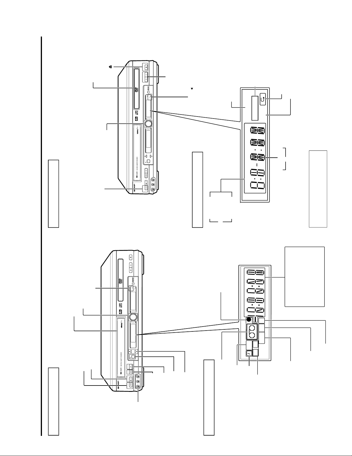
Sharp DV-NC65H User manual

1
DV-NC65H/S
DV-NC70H
SERVICE MANUAL VCR/DVD COMBINATION MODEL MODELS DV-NC65H/S/70H
S92P3DV-NC65H
SERVICE MANUAL
Page
1. IMPORTANT SERVICE NOTES ........................................................................................................ 2
2. FEATURES ........................................................................................................................................ 3
3. SPECIFICATIONS ............................................................................................................................. 3
4. PART NAMES .................................................................................................................................... 5
5. MAINTENANCE CHECK ITEMS AND EXECUTION TIME ............................................................. 14
6. DISASSEMBLY METHOD ............................................................................................................... 15
7. OPERATION OF PICKUP ............................................................................................................... 19
8. ADJUSTMENT, REPLACEMENT AND ASSEMBLY OF MECHANICAL UNITS ............................ 20
9. TEST MODE .................................................................................................................................... 43
10. MECHANISM OPERATION FLOWCHART AND TROUBLESHOOTING ....................................... 49
11.TROUBLESHOOTING ...................................................................................................................... 51
12. BLOCK DIAGRAMS ......................................................................................................................... 64
13. SCHEMATIC DIAGRAMS ................................................................................................................ 74
14. PRINTED WIRING BOARD ASSEMBLIES ..................................................................................... 96
15. REPLACEMENT PARTS LIST ...................................................................................................... 113
16. PACKING OF THE SET ................................................................................................................. 132
CONTENTS
In the interests of user-safety (Required by safety regula-
tions in some countries) the set should be restored to its
original condition and only parts identical to those specified
be used.
MODELS
DV-NC65H
DV-NC65S
DV-NC70H
VCR/DVD COMBINATION MODEL
SHARP CORPORATION
OPEN/CLOSE
OPERATE
EJECT/STOP
REW PLAY/X2
REC
CH VCR/DVD
SELECTOR
TIMER
VCR DVD
PLAY STOP
LINE IN 3 VIDEO L - AUDIO - R
/
DV-NC65
DVD / CD PLAYER
PAL
OPEN/CLOSE
OPERATE
EJECT/STOP
REW PLAY/X2
REC
CH VCR/DVD
SELECTOR
TIMER
VCR DVD
PLAY STOP
LINE IN 3 VIDEO L - AUDIO - R
/
DV-NC70H
DVD / CD PLAYER
PAL
DV-NC65H
DV-NC65S
DV-NC70H

2
DV-NC65H/S
DV-NC70H
Note:
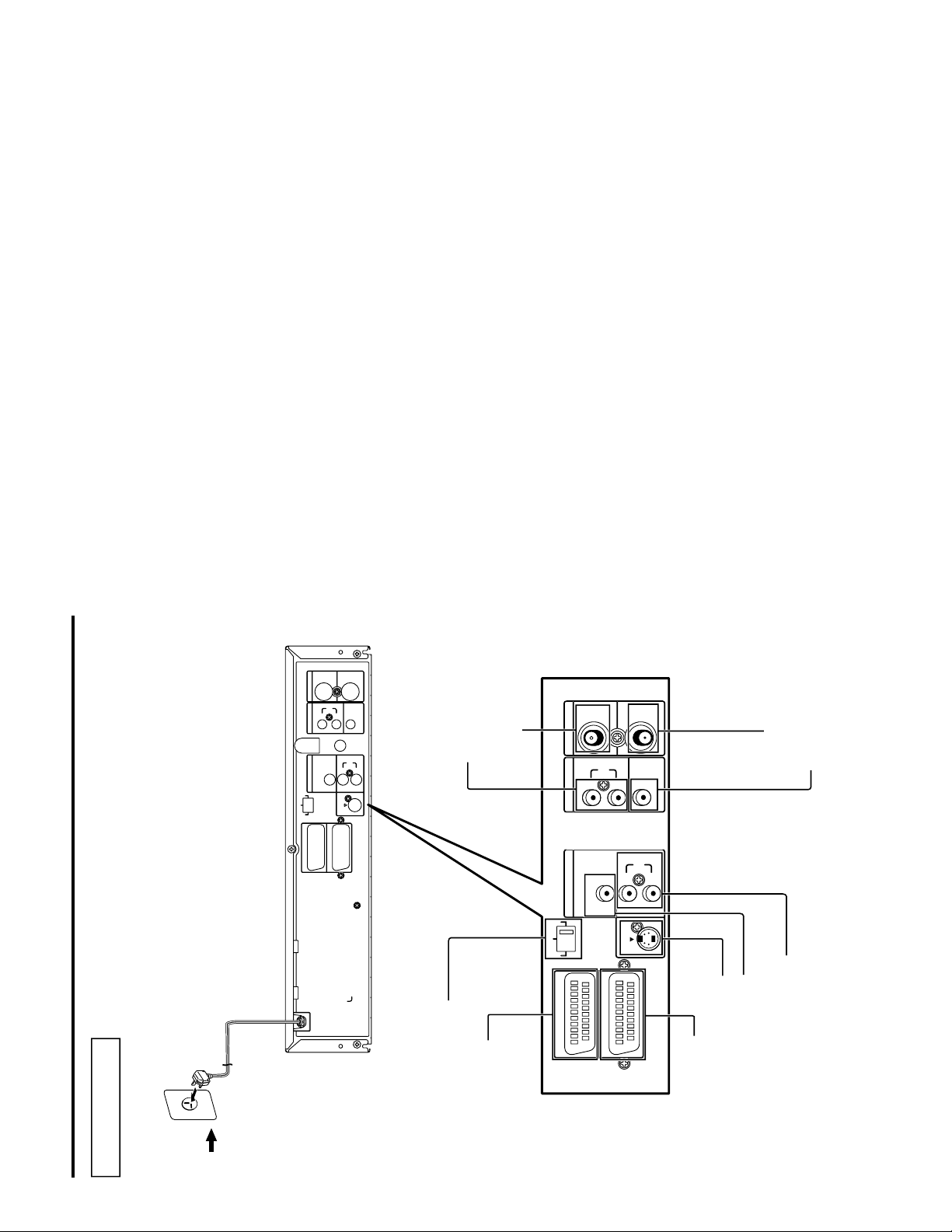
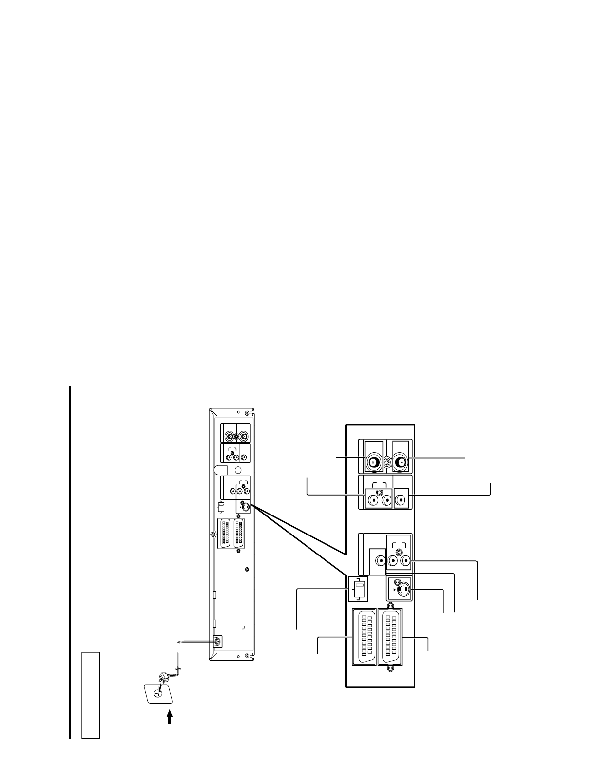
This unit can be used only where the power
supply is AC 230V-240V, 50Hz. It cannot be used
elsewhere.
CAUTION:
USE OF CONTROLS OR ADJUSTMENTS OR
PERFORMANCE OF PROCEDURES OTHER
THAN THOSE SPECIFIED HEREIN MAY RESULT
IN HAZARDOUS RADIATION EXPOSURE.
DO NOT STARE INTO THE LASER BEAM OR
VIEW WITH OPTICAL INSTRUMENT.
WARNING:
TO REDUCE THE RISK OF FIRE OR ELECTRIC
SHOCK, DO NOT EXPOSE THIS EQUIPMENT TO
RAIN OR MOISTURE.
TO REDUCE THE RISK OF FIRE OR ELECTRIC
SHOCK, AND ANNOYING INTERFERENCE, USE
THE RECOMMENDED ACCESSORIES ONLY.
Laser Diode Properties
Material: AlGaInP
Wave length: 650 nm
Emission Duration: Continuous
Laser output: Max. 0.7 mW
(Rear of product)
•This Unit is classified as a CLASS 1 LASER
product.
•The CLASS 1 LASER PRODUCT label is located
on the rear cover.
•This product contains a low power laser device.
To ensure continued safety do not remove any
cover or attempt to gain access to the inside of
the product. Refer all servicing to qualified
personnel.
Power Lead Protection
To avoid any malfunctions of the unit, and to protect
against electric shock, fire or personal injury, please
observe the following.
•Hold the plug firmly when connecting or
disconnecting the AC power lead.
•Keep the AC power lead away from heating
appliances.
•Never put any heavy object on the AC power lead.
•Do not attempt to repair or reconstruct the AC
power lead in any way.
CLASS 1
LASER PRODUCT
VARO! AVATTAESSA OLET ALTTIINA LASERSÄTEILYLLE.
ÄLÄ TUIJOTA SÄTEESEEN ÄLÄKÄ KATSO SITÄ OPTISEN LAITTEEN LÄPI.
VARNING - LASERSTRÅLNING NÄR DENNA DEL ÄR ÖPPNAD.
STIRRA EJ IN STRÅLEN OCH BETRAKTA EJ STRÅLEN GENOM OPTISKT
INSTRUMENT.
1. IMPORTANT SERVICE NOTES

3
DV-NC65H/S
DV-NC70H
2. FEATURES
ËË
ËË
ËCommon Features
• A DVD, CD player and VCR all in one.
• Simultaneous VCR recording and DVD playback.
ËË
ËË
ËVCR
• Hi-Fi Stereo Sound/Double-Azimuth 4-Heads
• 1 minute Rewind (E-180)
• S-VHS Simple Playback
• HQ (High Quality) Circuitry
• Simple Recording Timer
• Sharp Super Picture
ËË
ËË
ËDVD
• Plays DVD, CD (Digital Audio) discs as well as CD-R/CD-RW discs recorded in MP3 file format
• 3D Virtual Surround provides high-quality surround sound
• Digital Gamma correction
• Dolby Digital*1/DTS*2, MPEG Audio digital out capability
• High-quality digital images
• High-quality digital sound
*1Manufactured under license from Dolby Laboratories. "Dolby", "Pro Logic" and the double-D symbol are
trademarks of Dolby Laboratories.
*2"DTS" and "DTS Digital Surround" are trademarks of Digital Theater Systems, Inc.
3. SPECIFICATIONS
Signal System PAL (DV-NC65H/70H)
PAL/MESECAM (DV-NC65S)
INPUT/OUTPUT JACKS
DVD/VCR shared output jacks VIDEO jack: RCA Pin-jack
AUDIO jack: RCA Pin-jack
DVD output jacks VIDEO jack: S-Video jack
AUDIO jack: RCA Pin-jack
DIGITAL AUDIO IF: Coaxial digital (DV-NC65H/S)
: Coaxial digital and Optical digital (DV-NC70H)
AUDIO output jack: RCA Pin-jack
VIDEO input jacks VIDEO jack: SCART
AUDIO jack: SCART
VIDEO jack: RCA Pin-jack
AUDIO jack: RCA Pin-jack
VCR
Video Recording System Rotary Two-Head Helical Scanning
Number of Video Heads 4
Video Signal Standard PAL Colour System (DV-NC65H/70H)
PAL/MESECAM Colour System (DV-NC65S)
Audio Recording System 1 Stationary Head for Linear Audio
2 Rotary Heads for Hi-Fi stereo
Tape Width 12.7 mm
Tape Speed (PAL) (SP) 23.39 mm/sec.
(LP) 11.7 mm/sec.
(EP) 7.8 mm/sec.
(NTSC) (SP) 33.35 mm/sec. (Playback only)
(LP) 16.67 mm/sec. (Playback only)
(EP) 11.12 mm/sec. (Playback only)
Recording/Playback Time (SP) 240 min. (With E-240 Cassette)
(LP) 480 min. (With E-240 Cassette)
(EP) 720 min. (With E-240 Cassette)

4
DV-NC65H/S
DV-NC70H
3-1. ACCESSORIES
Accessories: Remote control unit ×1, "AA" size battery (R-6, UM/SUM-3) ×2,
AV cable ×1, RF cable (75 Ohm, 1 m) ×1
Channel Coverage UHF E21-E69 (DV-NC65H/70H)
VHF E2-E12 + S1-S41; UHF E21-E69 (DV-NC65S)
Antenna Input 75Ω
Video Input Input level: 0.5 to 2.0 Vp-p (75Ω)
Video Output Output level: 1.0 Vp-p (75Ω)
Audio Output Input level: –3.8 dBs (47kΩ)
(0 dBs = 0.775 Vrms)
Audio Output Output level: –3.8 dBs (1kΩ)
(0 dBs = 0.775 Vrms)
Hi-Fi Audio Dynamic Range: 90 dB
Frequency Response: 20 Hz-20 kHz
Memory Backup 10 minutes
DVD
DVD/VCR shared Video output Output level: 1 Vp-p (75Ω)
S video output Y output level: 1 Vp-p (75Ω)
C output level: 0.3 Vp-p (75Ω)
Audio output Output level: 2 Vrms (1 kHz, 0 dB)
Video signal horizontal resolution 500 lines (450 lines min.)
S/N ratio 60 dB (50 db min.)
Audio signal frequency characteristics For DVD linear PCM playback:
4 Hz to 22 kHz (48 kHz sampling)
CD playback: 4 Hz to 20 kHz (JEITA)
S/N ratio CD: 96 dB, 1 kHz (JEITA)
Dynamic range DVD linear PCM: 96 dB (JEITA)
CD: 96 dB (JEITA)
Total harmonic distortion ratio CD: 0.006% (JEITA)
Pickup Wave length: 650 nm (DVD) / 780nm (CD)
Laser output: Max. 0.7 mW
Operating temperature 5 °C to 35 °C (41 °F to 95 °F)
Storage temperature –20 °C to 55 °C (–4 °F to 131 °F)
Power supply 230 V-240 V AC, 50 Hz
Power consumption 21 W
Dimensions W × H × D: 430 mm × 93.5 mm × 350 mm (DV-NC65H/S)
W × H × D: 430 mm × 93.5 mm × 356 mm (DV-NC70H)
Weight 5.3 kg
Specifications are subject to change without notice.
Weight and dimensions are approximate.

5
DV-NC65H/S
DV-NC70H
OPEN/CLOSE
OPERATE
EJECT/STOP
REW PLAY/X2
REC
CH
VCR/DVD
SELECTOR
TIMER
VCR DVD
PLAY STOP
LINE IN 3 VIDEO L - AUDIO - R
/
DV-NC65H
DVD / CD PLAYER
PAL
DVD Main Unit (Front)
DVD Front Panel Display
You can toggle between 1and 2by
pressing the remote control unit’s
DISPLAY button.
VCR/DVD
Selector/Indicator
Disc tray
Disc operation buttons
(PLAY, STOP)
A B
TITLE TRACK CHAPTER TOTAL PROGRAM
VIRTUAL
ANGLE
Operation status/Time indicator
2
TITLE
indicator
TRACK
indicator
CHAPTER
indicator
1
PROGRAM indicator
VIRTUAL surround
indicator
REPEAT indicator
ANGLE indicator
OPEN/CLOSE
VCR DVD indicator
OPERATE
4. PART NAMES
OPEN/CLOSE
OPERATE
EJECT/STOP
REW PLAY/X2
REC
CH
VCR/DVD
SELECTOR
TIMER
VCR DVD
PLAY STOP
LINE IN 3 VIDEO L - AUDIO - R
/
DV-NC65H
DVD / CD PLAYER
PAL
VCR Main Unit (Front)
VCR Front Panel Display
Front AUDIO/
VIDEO input
jack
EJECT/STOP
OPERATE
PLAY/X2
REC
REW
CH
'
/"
Cassette compartment
VCR/DVD SELECTOR
TIMER indicator
SEPVP D
VCR
LR
VCR Mode
Indicator
Cassette-in Indicator
Timer Recording
Indicator
Tape Speeds
Indicator
Audio Output
Indicator
Video Programming System/
Programme Delivery Control
Indicator
Decoder Indicator
Recording Indicator
Clock Indicator
Channel Indicator
Tape Counter Indicator
Tape Status Indicator
Tape Remain Indicator
DV-NC65H (Front)

6
DV-NC65H/S
DV-NC70H
Main Unit (Rear)
VCR/DVD shared
AUDIO output jacks
ANTENNA IN (antena
or cable input)
OUTPUT SELECTOR
SCART LINE 2 socket
DVD AUDIO output jacks
VCR/DVD shared VIDEO
output jack
ANTENNA OUT
DVD S-VIDEO output jack
SCART LINE 1 (TV) socket
DVD DIGITAL AUDIO output jack
LINE 2
LINE 1 (TV)
S-VIDEO
OUTPUT
SELECTOR
RGB VIDEO
S-VIDEO
DIGITAL
AUDIO
VCR/DVD OUT
R
L
AUDIO
VIDEO
ANTENNA
IN
OUT
DVD OUT
R
L
AUDIO
To an AC outlet
LINE 2
LINE 1 (TV)
S-VIDEO
OUTPUT
SELECTOR
RGB VIDEO
S-VIDEO
DIGITAL
AUDIO
VCR/DVD OUT
R
L
AUDIO
VIDEO
ANTENNA
IN
OUT
DVD OUT
R
L
AUDIO
DV-NC65H (Rear)

7
DV-NC65H/S
DV-NC70H
Remote (VCR Operation Buttons)
»The explanations on this page use the VCR/DVD CHANGE Switch in the VCR position.
REV FWD
STOP
OPEN/
CLOSE
VCR/DVD
SELECTOR
VCR MENU
DVD SETUP
TAPE
SPEED
ON
SCREEN
TITLE
DVD MENU
DISPLAY
FUNCTION
CONTROL
PROG/
REPEAT
ANGLE
CLEAR
RETURN
OPERATE
TIMER
ON/OFF
PLUSCODE
EJECT
SET
ENTER
ZERO BACK
SKIP SEARCH
TV/VCR
VCR DVDAM/PM
INPUT SELECT
PAUSE/STILL
REC
SLOW
CH
VCR DVD
SKIP
DPSS
AUDIO
OUTPUT
VCR/ DVD COMBINATION
/
RRMCGA069WJSA
ON SCREEN
TIMER ON/OFF
OPERATE
DISPLAY
CLEAR
Number buttons
TAPE SPEED
VCR/DVD CHANGE Switch
PLUS CODE
VCR/DVD SELECTOR
EJECT
VCR MENU
SET
ZERO BACK
SKIP SEARCH
TV/VCR
INPUT SELECT
AUDIO OUTPUT
VCR DVD
CURSOR ( / / / )
CH /
STOP
REW
FF
PAUSE/ STILL
REC
PLAY
AM/PM or
-/--
SLOW
—
/
±
, DPSS /
SLOW
PLAY
REV FWD
STOP
OPEN/
CLOSE
VCR/DVD
SELECTOR
VCR MENU
DVD SETUP
TAPE
SPEED
ON
SCREEN
TITLE
DVD MENU
DISPLAY
FUNCTION
CONTROL
PROG/
REPEAT
ANGLE
CLEAR
RETURN
OPERATE
TIMER
ON/OFF
PLUSCODE
EJECT
SET
ENTER
ZERO BACK
SKIP SEARCH
TV/VCR
VCR DVDAM/ PM
INPUT SELECT
PAUSE/STILL
REC
SLOW
CH
VCR DVD
SKIP
DPSS
AUDIO
OUTPUT
VCR/ DVD COMBINATION
/
RRMCGA069WJSA
ON SCREEN
OPERATE
DISPLAY
FUNCTION CONTROL
RETURN
TITLE
Number buttons
REV
STOP
CURSOR ( / / / )
VCR/DVD SELECTOR
PROG, REPEAT
ANGLE
PLAY
DVD MENU
OPEN/CLOSE
DVD SETUP
ENTER
PAUSE/ STILL
FWD
SLOW
VCR/DVD CHANGE Switch
SKIP
PLAY
»
Do not subject the Remote to shock, water or excessive humidity.
»
The Remote may not function if the Unit sensor is in direct sunlight or any other strong light.
»
Incorrect use of batteries may cause them to leak or burst. Read the battery warnings and use the batteries properly.
»
Do not mix old and new batteries, or mix brands in use.
»
Remove the batteries if you do not use the Remote for an extended period of time.
Remote (DVD Operation Buttons)
»The explanations on this page use the VCR/DVD CHANGE Switch in the DVD position.
DV-NC65H (Remote Control)

8
DV-NC65H/S
DV-NC70H
VCR Main Unit (Front)
VCR Front Panel Display
OPEN/CLOSE
OPERATE
EJECT/STOP
REW PLAY/X2
REC
CH
VCR/DVD
SELECTOR
TIMER
VCR DVD
PLAY STOP
LINE IN 3 VIDEO L - AUDIO - R
/
DV-NC65S
DVD / CD PLAYER
PAL
Front AUDIO/
VIDEO input
jack
EJECT/STOP
OPERATE
PLAY/X2
REC
REW
VCR/DVD SELECTOR
TIMER indicator
SEPVP D
VCR
LR
VCR Mode
Indicator
Cassette-in Indicator
Timer Recording
Indicator
Tape Speeds
Indicator
Audio Output
Indicator
Video Programming System/
Programme Delivery Control
Indicator
Decoder Indicator
Recording Indicator
Clock Indicator
Channel Indicator
Tape Counter Indicator
Tape Status Indicator
Tape Remain Indicator
CH '/"
Cassette compartment
DV-NC65S (Front)
DVD Main Unit (Front)
DVD Front Panel Display
You can toggle between 1and 2by
pressing the remote control unit’s
DISPLAY button.
OPEN/CLOSE
OPERATE
EJECT/STOP
REW PLAY/X2
REC
CH
VCR/DVD
SELECTOR
TIMER
VCR DVD
PLAY STOP
LINE IN 3 VIDEO L - AUDIO - R
/
DV-NC65S
DVD / CD PLAYER
PAL
OPERATE VCR/DVD
Selector/Indicator
Disc tray
Disc operation buttons
(PLAY, STOP)
VCR DVD indicator
A B
TITLE TRACK CHAPTER TOTAL PROGRAM
VIRTUAL
ANGLE
Operation status/Time indicator
2
TITLE
indicator
TRACK
indicator
CHAPTER
indicator
1
PROGRAM indicator
VIRTUAL surround
indicator
REPEAT indicator
ANGLE indicator
OPEN/CLOSE

9
DV-NC65H/S
DV-NC70H
DV-NC65S (Rear)
Main Unit (Rear)
VCR/DVD shared
AUDIO output jacks
ANTENNA IN (antena
or cable input)
OUTPUT SELECTOR
SCART LINE 2 socket
To an AC outlet
DVD AUDIO output jacks
VCR/DVD shared VIDEO
output jack
ANTENNA OUT
DVD S-VIDEO output jack
SCART LINE 1 (TV) socket
DVD DIGITAL AUDIO output jack
LINE 2
LINE 1 (TV)
S-VIDEO
OUTPUT
SELECTOR
RGB VIDEO
S-VIDEO
AUDIO
VCR/DVD OUT
R
L
AUDIO
VIDEO
ANTENNA
IN
OUT
DVD OUT
LINE 2
LINE 1 (TV)
S-VIDEO
OUTPUT
SELECTOR
RGB VIDEO
S-VIDEO
AUDIO
VCR/DVD OUT
R
L
AUDIO
VIDEO
ANTENNA
IN
OUT
DVD OUT
R
L
AUDIO
R
L
AUDIO

10
DV-NC65H/S
DV-NC70H
Remote (VCR Operation Buttons)
»The explanations on this page use the VCR/DVD CHANGE Switch in the VCR position.
REV FWD
OPEN/
CLOSE
VCR/DVD
SELECTOR
VCR MENU
DVD SETUP
TAPE
SPEED
ON
SCREEN
TITLE
DVD MENU
DISPLAY
FUNCTION
CONTROL
PROG/
REPEAT
ANGLE
CLEAR
RETURN
OPERATE
TIMER
ON/OFF
SHOWVIEW
EJECT
SET
ENTER
ZERO BACK
SKIP SEARCH
TV/VCR
VCR DVDAM/PM
INPUT SELECT
PAUSE/STILL
REC
SLOW
CH
VCR DVD
SKIP
DPSS
AUDIO
OUTPUT
VCR/ DVD COMBINATION
/
RRMCGA055WJSA
ON SCREEN
TIMER ON/OFF
OPERATE
DISPLAY
CLEAR
Number buttons
TAPE SPEED
VCR/DVD CHANGE Switch
S
HOW
V
IEW
VCR/DVD SELECTOR
EJECT
VCR MENU
SET
ZERO BACK
SKIP SEARCH
TV/VCR
INPUT SELECT
AUDIO OUTPUT
VCR DVD
CURSOR ( / / / )
CH /
STOP
REW
FF
REC
PLAY
AM/PM or
-/--
SLOW
—
/
±
, DPSS /
SLOW
PLAY
STOP
PAUSE/ STILL
REV FWD
STOP
OPEN/
CLOSE
VCR/DVD
SELECTOR
VCR MENU
DVD SETUP
TAPE
SPEED
ON
SCREEN
TITLE
DVD MENU
DISPLAY
FUNCTION
CONTROL
PROG/
REPEAT
ANGLE
CLEAR
RETURN
OPERATE
TIMER
ON/OFF
SHOWVIEW
EJECT
SET
ENTER
ZERO BACK
SKIP SEARCH
TV/VCR
VCR DVDAM/ PM
INPUT SELECT
PAUSE/STILL
REC
SLOW
CH
VCR DVD
SKIP
DPSS
AUDIO
OUTPUT
VCR/ DVD COMBINATION
/
RRMCGA055WJSA
ON SCREEN
OPERATE
DISPLAY
FUNCTION CONTROL
RETURN
TITLE
Number buttons
REV
STOP
CURSOR ( / / / )
VCR/DVD SELECTOR
PROG, REPEAT
ANGLE
PLAY
DVD MENU
OPEN/CLOSE
DVD SETUP
ENTER
PAUSE/ STILL
FWD
SLOW
VCR/DVD CHANGE Switch
SKIP
PLAY
»Do not subject the Remote to shock, water or excessive humidity.
»The Remote may not function if the Unit sensor is in direct sunlight or any other strong light.
»Incorrect use of batteries may cause them to leak or burst. Read the battery warnings and use the batteries properly.
»Do not mix old and new batteries, or mix brands in use.
»Remove the batteries if you do not use the Remote for an extended period of time.
Remote (DVD Operation Buttons)
»The explanations on this page use the VCR/DVD CHANGE Switch in the DVD position.
DV-NC65S (Remote Control)

11
DV-NC65H/S
DV-NC70H
DV-NC70H (Front)
DVD Main Unit (Front)
DVD Front Panel Display
You can toggle between 1and 2by
pressing the remote control unit’s
DISPLAY button.
OPEN/CLOSE
OPERATE
EJECT/STOP
REW PLAY/X2
REC
CH
VCR/DVD
SELECTOR
TIMER
VCR DVD
PLAY STOP
LINE IN 3 VIDEO L - AUDIO - R
/
DV-NC70H
DVD / CD PLAYER
PAL
OPERATE VCR/DVD
Selector/Indicator
Disc tray
Disc operation buttons
(PLAY, STOP)
VCR DVD indicator
A B
TITLE TRACK CHAPTER TOTAL PROGRAM
VIRTUAL
ANGLE
Operation status/Time indicator
2
TITLE
indicator
TRACK
indicator
CHAPTER
indicator
1
PROGRAM indicator
VIRTUAL surround
indicator
REPEAT indicator
ANGLE indicator
OPEN/CLOSE
VCR Main Unit (Front)
VCR Front Panel Display
OPEN/CLOSE
OPERATE
EJECT/STOP
REW PLAY/X2
REC
CH
VCR/DVD
SELECTOR
TIMER
VCR DVD
PLAY STOP
LINE IN 3 VIDEO L - AUDIO - R
/
DV-NC70H
DVD / CD PLAYER
PAL
Front AUDIO/
VIDEO input
jack
EJECT/STOP
OPERATE
PLAY/X2
REC
REW
Cassette compartment
VCR/DVD SELECTOR
TIMER indicator
SEPVP D
VCR
LR
VCR Mode
Indicator
Cassette-in Indicator
Timer Recording
Indicator
Tape Speeds
Indicator
Audio Output
Indicator
Video Programming System/
Programme Delivery Control
Indicator
Decoder Indicator
Recording Indicator
Clock Indicator
Channel Indicator
Tape Counter Indicator
Tape Status Indicator
Tape Remain Indicator
CH '/"

12
DV-NC65H/S
DV-NC70H
Main Unit (Rear)
VCR/DVD shared
AUDIO output jacks
ANTENNA IN (antena
or cable input)
OUTPUT SELECTOR
SCART LINE 2 socket
To an AC outlet
DVD AUDIO output jacks
VCR/DVD shared VIDEO
output jack
ANTENNA OUT
DVD Coaxial/Optical
DIGITAL output jack
DVD S-VIDEO output jack
SCART LINE 1 (TV) socket
DVD DIGITAL AUDIO output jack
LINE 2
LINE 1 (TV)
S-VIDEO
OUTPUT
SELECTOR
RGB VIDEO
S-VIDEO
DIGITAL
AUDIO
OPT.
R
L
AUDIO
VCR/DVD OUT
R
L
AUDIO
VIDEO
ANTENNA
IN
OUT
LINE 2
LINE 1 (TV)
S-VIDEO
OUTPUT
SELECTOR
RGB VIDEO
S-VIDEO
DIGITAL
AUDIO
OPT.
R
L
AUDIO
VCR/DVD OUT
R
L
AUDIO
VIDEO
ANTENNA
IN
OUT
DVD OUT
DVD OUT
DV-NC70H (Rear)

13
DV-NC65H/S
DV-NC70H
Remote (VCR Operation Buttons)
»The explanations on this page use the VCR/DVD CHANGE Switch in the VCR position.
REV FWD
STOP
OPEN/
CLOSE
VCR/DVD
SELECTOR
VCR MENU
DVD SETUP
TAPE
SPEED
ON
SCREEN
TITLE
DVD MENU
DISPLAY
FUNCTION
CONTROL
PROG/
REPEAT
ANGLE
CLEAR
RETURN
OPERATE
TIMER
ON/OFF
PLUSCODE
EJECT
SET
ENTER
ZERO BACK
SKIP SEARCH
TV/VCR
VCR DVDAM/PM
INPUT SELECT
PAUSE/STILL
REC
SLOW
CH
VCR DVD
SKIP
DPSS
AUDIO
OUTPUT
VCR/ DVD COMBINATION
/
RRMCGA054WJSA
ON SCREEN
TIMER ON/OFF
OPERATE
DISPLAY
CLEAR
Number buttons
TAPE SPEED
VCR/DVD CHANGE Switch
PLUS CODE
VCR/DVD SELECTOR
EJECT
VCR MENU
SET
ZERO BACK
SKIP SEARCH
TV/VCR
INPUT SELECT
AUDIO OUTPUT
VCR DVD
CURSOR ( / / / )
CH /
STOP
REW
FF
PAUSE/ STILL
REC
PLAY
AM/PM or /
62
SLOW
—
/
±
, DPSS /
SLOW
PLAY
-/--
REV FWD
STOP
OPEN/
CLOSE
VCR/DVD
SELECTOR
VCR MENU
DVD SETUP
TAPE
SPEED
ON
SCREEN
TITLE
DVD MENU
DISPLAY
FUNCTION
CONTROL
PROG/
REPEAT
ANGLE
CLEAR
RETURN
OPERATE
TIMER
ON/OFF
PLUSCODE
EJECT
SET
ENTER
ZERO BACK
SKIP SEARCH
TV/VCR
VCR DVDAM/ PM
INPUT SELECT
PAUSE/STILL
REC
SLOW
CH
VCR DVD
SKIP
DPSS
AUDIO
OUTPUT
VCR/ DVD COMBINATION
/
RRMCGA054WJSA
ON SCREEN
OPERATE
DISPLAY
FUNCTION CONTROL
RETURN
TITLE
Number buttons
REV
STOP
CURSOR ( / / / )
VCR/DVD SELECTOR
PROG, REPEAT
ANGLE
PLAY
DVD MENU
OPEN/CLOSE
DVD SETUP
ENTER
PAUSE/ STILL
FWD
SLOW
VCR/DVD CHANGE Switch
SKIP
PLAY
»Do not subject the Remote to shock, water or excessive humidity.
»The Remote may not function if the Unit sensor is in direct sunlight or any other strong light.
»Incor rect use of batteries may cause them to leak or burst. Read the battery warnings and use the batteries properly.
»Do not mix old and new batteries, or mix brands in use.
»Remove the batteries if you do not use the Remote for an extended period of time.
Remote (DVD Operation Buttons)
»The explanations on this page use the VCR/DVD CHANGE Switch in the DVD position.
DV-NC70H (Remote Control)

14
DV-NC65H/S
DV-NC70H
5. MAINTENANCE CHECK ITEMS AND EXECUTION TIME
Parts Maintained 1,000 hrs. 2,000 hrs.
Pickup
Spindle Unit
Sled Motor
Loading Motor
Belt
Note : Part Replacement
: Cleaning
(For cleaning, use a lint-free cloth danpened with pure isopropyl alcohol.)
Use the following table as a guide to maintain the mechanical parts in good operating condition.
CARES WHEN USING THE PICKUP
1. The laser light having wavelength 650 nm is emitted from the objective lens. BE CAREFUL SO THAT THE LASER
LIGHT DOES NOT ENTER DIRECTLY INTO YOUR EYE.
2. The semiconductor laser may be easily damaged by electrostatic charges. When handling the pickup, take care so that
the electrostatic charge is not generated.
3. The semiconductor laser may be easily damaged by overcurrent. Use the power supply unit which does not give any
spike current when the power is turned on and off.
4. Carefully remove the dust and dirt from the objective lens with the lens blower.
When handling the objective lens, take due care so that it is not contaminated with fingerprint, etc. If the objective lens
is contaminated, impregnate the cleaning paper with a small quantity of solvent (isopropyl alcohol), and gently wipe to
clean.
5. The ozone layer depleting components (ODC) are not used in the production process for the product.
MECHANICAL PARTS REGUIRING PERIODICAL INSPECTION

15
DV-NC65H/S
DV-NC70H
6. DISASSEMBLY METHOD
6-1. DISASSEMBLY METHOD
1) Removing the top cabinet.
(1) Remove the four screws 1and the three screws 2.
2) Removing the front panel.
(1) Remove the two screws 3.
(2) Release the six hooks 4.
3) Removing the front PWB.
(1) Release the one hook 5and tilt the PWB
toward you to remove it.
(2) Release the one hook 6and tilt the PWB
toward you to remove it.
4) Removing the DVD mechanism.
(1) Remove the four screws 7 to remove the DVD REINF.
angle.
(2) Remove the two screws 8and the two screws 9.
(3) Remove the two screws 0 to remove the angle (DVD) .
(4) Remove the DVD shield (lower) q.
2
1
1
4
35
6
4
4
4
9
10
9
10
8
7
12
11
(5) Remove the four screws wto remove the DVD main PWB
unit from the angle (DVD).

16
DV-NC65H/S
DV-NC70H
6) Removing the cassette housing control/ the VCR mechanism.
(1) Remove the two screws u.
(2) Remove the two screws i.
(3) Remove the one screw o.
13
14
16
15
17
18
19
21
20
23
22
24
(6) Remove the two screws e to remove the power PWB unit.
7) Removing the rear panel/ the antenna terminal cover/
the VCR main PWB unit.
(1) Remove the five screws pat rear side.
(four screws in DV-NC65H/S)
(2) Remove the one screw afor Tuner.
(3) Remove the rear panel.
(4) Remove the two screws s.
5) Removing the rear PWB unit.
(1) Remove the two screws r(for 21 pin) at rear side.
(2) Remove the five screws tto remove the rear PWB unit
and the earth plate.
(3) Remove the five connectors of the FFCs.
(4) Remove the rear PWB unit.
(5) Remove the four screws yto remove the rear PWB
holder.
(5) Remove the antenna terminal cover.
(6) Remove the one screw d.
(7) Remove the VCR main PWB unit.
8) Removing the bottom plate.
(1) Remove the one screw f.

17
DV-NC65H/S
DV-NC70H
Parts Code Price Code Name/Description
QCNW-8571GEZZ AN Extension cable (wire), 9pin 500mm
DVD Main CN3201–Power CN201
6-2. EXTENSION CABLE USE POINT (ONE PLACE)
Extension Cable Diagram
Power PWB
CN201
Tuner
CN3201
DVD Main PWB
DVD Mechanism
F-AV PWB VCR/DVD Display PWB
VCR Mechanism
VCR Main PWB
QCNW-8571GEZZ
9 pin

18
DV-NC65H/S
DV-NC70H
<Replacing the Pickup and the Spindle Motor>
Since the Pickup optical axis and turntable inclination of DVD are adjusted with higher accuracy, make a replacement as a
mechanism service chassis ass'y.
Front Side
Sled Motor Lead Wire
Pickup FFC
Traverse Fixing Screw
Loading Motor Lead Wire
Pickup Interface PWB
Pickup FFC
Short Land
6-3. REPLACEMENT OF MAIN PARTS
<Take out disk>
1. Remove the mechanism with angle from the set. (refer to 33 on page 130. Remove K , M , N )
2. It is in such cases as the thin driver, and it is pushed in slowly, and a tray is drawn in the arrow direction the Slide Rack on the
left of the base chassis.
3. Take out disk.
<Disassembling and assembling the mechanism chassis>
1. After setting the mechanism chassis to the angle state, ground it to prevent the electrostatic discharge damage of the pickup.
2. Remove the DVD Shield (lower) 40 (refer to the illustration on page 130).
3. Remove P , Q from the DVD Main PWB Unit 27 . (Pickup Relay FFC 58 isn't removed.) (refer to the illustration on page 130)
4. Remove screws fixing the base chassis (located at the back right and at front left when facing the set).
5. With the Pickup FFC connected, turn over the base chassis and short (solder) two short lands on the pickup interface PWB in
order to prevent the electrostatic discharge damage of the pickup.
6. Remove the Pickup FFC from the Main PWB.
7. Remove the Pickup FFC from the Pickup Interface PWB.
8. Remove the Traverse Fixing Screws to remove the Traverse Chassis ass'y.
Note: After assembling and wiring, remove the solder joint of the short land. If short-circuited, a disk is not played back.

19
DV-NC65H/S
DV-NC70H
7. OPERATION OF PICKUP
7-1. CIRCUIT CONFIGURATION OF PICKUP
The pickup unit reads signals from the disk, and the flexible cable is connected to the board. The following signals flow through the
cable.
7-2. EQUIVALENT CIRCUIT OF PICKUP 7-3. POLARITIES OF SIGNAL
Focus When electric current is flowed
FO+, FO- from FO+ to FO-, the lens comes
to near the disk.
Tracking When electric current is flowed
TR+, TR- from TR+ to TR-, the lens goes
toward the outer circumference.
FO+
TR–
TR+
FO–
ACTUATOR
OSC V
OS
–
+
–
+
–
+
–
+
HOLOGRAM LASER UNIT
1
2
3
4
5
6
7
8
9
10
11
12
13
14
15
16
17
18
19
20
1
TR–
FO+
TR+
FO–
VR
PD
V
CC
GND
LD
GND
V
OS
NC
NC
V
ref
(VCC/2)
VA
VD
NC
GND
VB
VC
(NC)
Power adjust
HIGH-FREQUENCY CONVOLUTION
LD
PD
VA
VB
VC
VD
V
ref
V
cc
GND
7-4. SIGNALS OF PICKUP
7-4-1. Tracking drive signal (TR+, TR-)
The signal drives the tracking servo mechanism which projects the beam on the track by moving the objective lens (OL) to the outer
or inner circumference (at a right angle against the track) of the disk.
7-4-2. Focus drive signal (FO+, FO-)
The signal drives the focus servo mechanism which aligns the focus on the pit of the disk
by elevating OL (vertically against the disk surface.)
The VR terminal is connected to GND.
2-focus objective lens
Actuator assembly
7-4-3. Monitor Diode (PD)
Since the laser diode largely varies output of the laser light even if the flowing current is slightly varied, the projection
light is detected with the monitor diode to control the laser light to be equally output.
Since the current varies on the monitor diode according to the intensity of the received light of the laser diode, the drive current of
the laser diode is reduced if the current of the monitor diode increases. On the contrary, the drive current of the laser diode is increased
if the current of the monitor diode decreases.
As the projection light of the laser diode becomes stronger, the current of the monitor diode increases to increase the current which
flows into the monitor diode output (PD). This is input to the pin 44 of IC301 and is compared with the reference voltage to control
the drive current of the laser diode.
The circuit is called ALPC (Automatic Laser Power Control).
7-4-4. Laser diode drive current control (LD)
Power supply to drive the laser diode
7-4-5. High-frequency convolution module power supply (VOSC)
The high-frequency convolution imposes the high-frequency signal on the DC current to impose the high frequency on the drive
current of the laser. Thus, the interference of outgoing light and reflected light is prevented.
LD PD
7-4-6. HF Signal (VA, VB, VC, VD)
Signals recorded in the disk
When the quantity of laser light increases, the
current shown in figure increases and the PD
terminal voltage rises.
IC301 is used to control. The LD terminal voltage
lowers, and the quantity of light reduces. (IC301 is
actuated by voltage input.)

20
DV-NC65H/S
DV-NC70H
Video Audio HiFi Audio Track
625 Monoscope 6 kHz — 35 µm
VROCPSV CK
11.
JiGHMEC-M005 CK
10. JiGDRiVER-6 BM
9.
JiGDRiVERH-4
AP
4. Torque Driver JiGTD1200 CB
8. ADJUSTMENT, REPLACEMENT AND ASSEMBLY OF MECHANICAL UNITS
The explanation given below relates to the on-site general service (field service) but it does not relates to the adjustment
and replacement which need high-grade equipment, jigs and skill. For example, the drum assembling, replacement and
adjustment service must be performed by the person who have finished the technical courses.
8-1. MECHANISM CONFIRMATION ADJUSTMENT JIG
So as to perform completely the mechanism adjustment prepare the following special jigs. So as to maintain the initial
performance of the machine the maintenance and check are necessary. Utmost care must be taken so that the tape is
not damaged. If adjustment needs any jig, be sure to use the required jig.
JiGTG1200 CN
JiGMP0001 BY
1. Torque Cassette Meter JiGVHT-063 CZ
No. Jig ltem Part No. Code Configuration Remarks
JiGTG0090 CM
3. Torque Gauge Head JiGTH0006 AW
JiGRH0002 BR
JiGSG2000 BS
JiGSG0300 BF
7. JiGADP003 BK
Tension Gauge
These Jigs are used for checking
and adjusting the reel disk height.
When fixing any part to the threaded
hole using resin with screw, use the
jig. (Specified torque 5 kg)
This cassette torque meter is used for check-
ing and adjusting the torque of take-up for
measuring tape back tension.
These Jigs are used for checking
and adjusting the torque of take-up
and supply reel disks.
Master Plane Jig and
Reel Disk Height
Adjusting Jig
Pinch pressing force
measuring jig
This Jig is used with the tension
gauge. Rotary transformer clearance
adjusting jig.
There are two gauges used for the
tension measurements, 300 g and
2.0 kg.
This tape is especially used for elec-
trical fine adjustment.
This screwdriver is used for adjusting the
guide roller height.
For X value adjustment
This Jig is used for adjustment
of tension pole.
X value adjustment
gear driver
Tension Pole
Adjustment Driver
625 Monoscope 6 kHz
and and — 49 µm
Colour bar 1 kHz
2. Torque Gauge
6.
5.
8. Alignment Tape
Guide roller height
adjustment driver
Other manuals for DV-NC65H
1
This manual suits for next models
2
Table of contents
Other Sharp DVD Player manuals

Sharp
Sharp DV-SL80U User manual

Sharp
Sharp DV-S1X User manual

Sharp
Sharp DV-SV90S(Y) User manual

Sharp
Sharp DV-760S User manual

Sharp
Sharp DV-SV 80 H User manual

Sharp
Sharp DV-S15H User manual

Sharp
Sharp DV-SL1000W User manual

Sharp
Sharp DV-SV80S(G) User manual

Sharp
Sharp DV-SL16H User manual

Sharp
Sharp DV-NC80W User manual

Sharp
Sharp DV-SV80S(B) User manual

Sharp
Sharp DV-SV 80 H User manual

Sharp
Sharp DV-SL80X User manual

Sharp
Sharp BD-HP90RU User manual

Sharp
Sharp DV-720S User manual

Sharp
Sharp DV-S1S(Y) User manual

Sharp
Sharp DV-SV90S(B) User manual

Sharp
Sharp DV-SL2000W User manual

Sharp
Sharp DV-SL1500W User manual

Sharp
Sharp DV-560H User manual