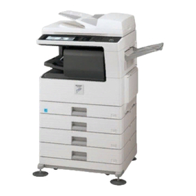
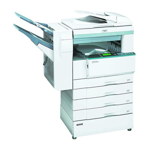
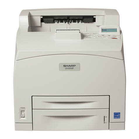
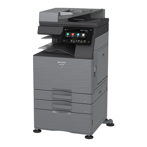
Sharp AR-C260P User manual

•BEFORE USING
THE PRODUCT
•
MANAGING THE MACHINE
•
OPERATION CONDITION
SETTINGS
•
PRINTING FROM THE
OPERATION PANEL
•PERIPHERAL DEVICES
•SPECIFICATIONS
1-1
2-1
3-1
4-1
5-1
6-1
Page
MODEL
AR-C260P
DIGITAL FULL COLOUR PRINTER
OPERATION MANUAL
(for general information)
Be sure to become thoroughly familiar with this manual to
gain the maximum benefit from the product.
Before installing this product, be sure to read the
installation requirements and cautions sections.
Be sure to keep all operation manuals handy for reference
including this manual, and operation manuals for any
optional equipment which has been installed.

The CE mark logo label is affixed on an equipment in case that the directives described in the above
sentence are applicable to the product. (This sentence is not applicable in any country where the above
directives are not required.)
Shielded Network cable, USB cable and Centronics cable must be used with this equipment to
maintain compliance with standards.
In some areas, the "POWER" switch positions are marked "I" and " " on the copier
instead of "ON" and "OFF".
The symbol " " denotes the copier is not completely de-energized but in a stand-by
condition at this "POWER" switch position.
If your copier is so marked, please read "I" for "ON" and " " for "OFF".
Caution!
For a complete electrical disconnection, pull out the main plug.
The socket-outlet shall be installed near the equipment and shall be easily
accessible.

0-1
OPERATION MANUALS
The following operation manuals are provided with the machine.
●
●●
●Operation manual (for general information) (this manual):
This manual provides general information about the machine, including safety information, loading paper,
removing misfeeds, and regular maintenance.
●
●●
●Software setup guide (for printer):
This explains the contents of the accompanying CD-ROM and the procedure for installing the software.
●
●●
●Operation manual (for printer)* :
This manual explains the procedures for using the machine as a printer.
●
●●
●Key operator's guide*:
This explains key operator programs for machine management.
Key operator programs are used by key operators to customize the machine to meet the needs of the customer.
* The Operation manual (for printer) and the Key operator's guide are provided as PDF files in the CD-ROM that
accompanies the AR-C260P.
These manuals are not provided as printed manuals.
NOTES
●Considerable care has been taken in preparing this manual. If you have any comments or concerns about the
manual, please contact your nearest SHARP Service Department.
●This product has undergone strict quality control and inspection procedures. In the unlikely event that a defect
or other problem is discovered, please contact your dealer or nearest SHARP Service Department.
●Aside from instances provided for by law, SHARP is not responsible for failures occurring during use of the
product or its options, or failures due to incorrect operation of the product and its options, or other failures, or for
any damage that occurs due to use of the product.

0-2
Improper installation may damage this product. Please note the following during initial installation and whenever the
machine is moved.
1. The machine should be installed near an accessible
power outlet for easy connection.
2. Be sure to connect the power cord only to a power
outlet that meets the specified voltage and current
requirements. Make sure that the outlet is properly
grounded.
●For the power supply requirements, see the
name plate on the main unit.
3. Do not install the machine in areas that are:
●damp, humid, or dusty
●exposed to direct sunlight
●poorly ventilated
●subject to extreme temperature or humidity
changes, e.g., near an air conditioner or heater.
4. Be sure to allow the required space around the
machine for servicing and proper ventilation.
A small amount of ozone is produced within the printer during operation. The emission level is insufficient to cause
any health hazard.
NOTE:
The present recommended long term exposure limit for ozone is 0.1 ppm (0.2 mg/m3) calculated as an 8 hr.
time-weighted average concentration.
However, since the small amount that is emitted may have an objectionable odor, it is advisable to place the copier
in a ventilated area.
INSTALLATION REQUIREMENTS

INSTALLATION REQUIREMENTS
0-3
Moving this machine
Pull out the four handles as shown below, grasp them firmly, and keep the machine horizontal while moving it.
If the machine has been placed on a stand/paper drawer:
The stand/paper drawer is on casters for moving. Unlock the adjusters of the stand/paper drawer and gently move
the machine, taking care to steady it to prevent it from toppling.
To lock and unlock the adjusters, see page 0-4.
Left side Right side
Bypass
tray
Exit
tray
Handles Handles
Caution
Two people are required to lift and carry this machine.
If the machine is to be left unused for a long time
If the machine is to be left unused for a month or longer, follow the procedure on pages 2-6 and 2-7 to release
the pressure on the fusing roller.
Before lifting the machine,
fold up the exit tray and
tape it securely to the
machine.
Before lifting the machine,
fold up the bypass tray
and tape it securely to the
machine.

0-4
CAUTIONS
1. Do not touch the photoconductive drum. Scratches
or smudges on the drum will cause dirty prints.
2. The fusing unit is extremely hot. Exercise care in
this area.
3. Four adjusters are provided on all optional
stand/paper drawer units. These adjusters should
be lowered until they contact the floor.
When moving the machine with the optional
stand/paper drawer, be sure to raise the adjusters.
Also, unlock the two casters at the front of the
optional stand/paper drawer. After moving the
machine, lower the four adjusters until they reach
the floor and lock the two casters.
4. Do not make any modifications to this machine.
Doing so may result in personal injury or damage to
the machine.
5. Since this machine is heavy, it is recommended that
it be moved by more than one person to prevent
injury.
6. When connecting this machine to a computer, be
sure to first turn both the computer and the machine
off.
7. Do not print anything which is prohibited from
printing by law. The following items are normally
prohibited from printing by national law. Other items
may be prohibited by local law.
●Money ●Stamps ●Bonds ●Stocks
●Bank drafts ●Checks ●Passports
●Driver's licences
"BATTERY DISPOSAL"
THIS PRODUCT CONTAINS A LITHIUM PRIMARY MEMORY BACK-UP BATTERY THAT MUST BE
DISPOSED OF PROPERLY. PLEASE CONTACT YOUR LOCAL SHARP DEALER OR AUTHORISED SERVICE
REPRESENTATIVE FOR ASSISTANCE IN DISPOSING OF THIS BATTERY.
Fusing unit
Adjuster
Lock
Lock Release
Caster
Release

0-5
CONTENTS
OPERATION MANUALS.................................................0-1
INSTALLATION REQUIREMENTS.................................0-2
●Moving this machine ....................................................0-3
CAUTIONS......................................................................0-4
CONTENTS ....................................................................0-5
CHAPTER 1
BEFORE USING THE PRODUCT
INTRODUCTION.............................................................1-2
MAIN FEATURES ...........................................................1-3
PART NAMES AND FUNCTIONS ..................................1-4
●Exterior ........................................................................1-4
●Interior..........................................................................1-5
●Part names and functions of peripheral devices..........1-6
●Operation panel ...........................................................1-8
CHAPTER 2
MANAGING THE MACHINE
LOADING PAPER...........................................................2-2
●Tray numbers...............................................................2-2
●Loading paper in paper tray 1......................................2-2
●Changing the paper size in paper tray 1......................2-3
●Loading paper in the bypass tray.................................2-4
●Loading paper in the stand/1 x 500 sheet paper
drawer/stand/3 x 500 sheet paper drawer ...................2-7
●Specifications (stand/1 x 500 sheet paper drawer/
stand/3 x 500 sheet paper drawer) ..............................2-7
●Loading paper in the duplex module/2 x 500 sheet
paper drawer................................................................2-8
●Specifications (duplex module/2 x 500 sheet paper
drawer).........................................................................2-8
●Specifications of paper trays........................................2-9
●Structure of the tray setting menu (except for the
bypass tray) ...............................................................2-11
●Setting the paper type (except for the bypass tray) ...2-12
●
Specifying the size when the paper size is set to "Extra"
(except for the bypass tray)
.........................................2-13
●Structure of the bypass tray setting menu .................2-14
●
Setting the paper type and paper size in the bypass tray
...2-15
CUSTOM SETTINGS....................................................2-17
●Basic procedure for custom settings..........................2-17
●Structure of the custom settings menu ......................2-18
●Setting items ..............................................................2-19
REPLACING THE TONER CARTRIDGES ...................2-20
STORAGE OF SUPPLIES ............................................2-22
CLEANING THE CABINET ...........................................2-22
MISFEED REMOVAL....................................................2-23
●Misfeed in the paper feed area ..................................2-24
●
Misfeed in the transport area, fusing area, and exit area
....2-25
●Misfeed in the stand/1 x 500 sheet paper drawer......2-26
●Misfeed in the stand/3 x 500 sheet paper drawer......2-26
●
Misfeed in the duplex bypass/inverter unit and duplex
module/2 x 500 sheet paper drawer............................ 2-27
TROUBLESHOOTING ..................................................2-29
CHAPTER 3
OPERATION CONDITION SETTINGS
CONFIGURING THE OPERATION CONDITION
SETTINGS...................................................................... 3-2
●
Basic procedure for operation condition settings (settings
that can be configured from the operation panel)
........... 3-2
●Structure of the operation conditions menu ................ 3-3
●Default settings ........................................................... 3-4
●PCL settings................................................................ 3-5
●Print PS errors............................................................. 3-6
CHAPTER 4
PRINTING FROM THE OPERATION
PANEL
HOLD JOB LIST
.............................................................. 4-2
CHAPTER 5
PERIPHERAL DEVICES
SADDLE STITCH FINISHER ......................................... 5-2
●Part names.................................................................. 5-2
●Specifications .............................................................. 5-2
●
Staple cartridge replacement and staple jam removal
.. 5-4
●Misfeed in the saddle stitch finisher ............................ 5-7
LARGE CAPACITY TRAY.............................................. 5-9
●Part name.................................................................... 5-9
●Specifications .............................................................. 5-9
●Loading paper ........................................................... 5-10
●Misfeed removal........................................................ 5-11
CHAPTER 6
SPECIFICATIONS
SPECIFICATIONS.......................................................... 6-2
●Printer.......................................................................... 6-2
●Duplex bypass/inverter unit (optional)......................... 6-4
●Print area..................................................................... 6-4
INDEX............................................................................. 6-5
1-1
CHAPTER 1
BEFORE USING THE
PRODUCT
This chapter contains basic information that should be read before using
the product.
Page
INTRODUCTION ...........................................................................................1-2
MAIN FEATURES..........................................................................................1-3
PART NAMES AND FUNCTIONS .................................................................1-4
●Exterior...................................................................................................1-4
●Interior....................................................................................................1-5
●Part names and functions of peripheral devices ....................................1-6
●Operation panel......................................................................................1-8

1-2
INTRODUCTION
This product is a high speed Digital full colour printer. Optional peripheral devices are available for the product that
expand its capabilities to meet a wide range of needs.
This manual contains general information on using the machine, including installation requirements, safety
information, and procedures for loading paper, replacing the toner cartridge, and removing misfeeds. For information
on printing from a computer connected to the machine and installing the printer driver, please see the additional
manuals that are provided with the machine.
Paper sizes
This machine allows use of standard sizes in both the AB and inch systems.
These are shown in the tables below.
The meaning of "R" in paper size indications in manuals
Some paper sizes can be placed in either the portrait or landscape orientations. To differentiate between landscape
and portrait, the landscape orientation size indication will contain an "R". These are indicated as A4R, B5R, 8-1/2"
x 11"R, 5-1/2" x 8-1/2"R, etc. Sizes that can be placed only in the landscape orientation ( A3, B4, 11" x 17", 8-1/2"
x 14", 8-1/2" x 13") do not contain the "R" in their size indication.
Size indication with "R"
Landscape orientation
Size indication without "R"
Portrait orientation
Sizes in the inch system
When the machine is being
operated from the operation panel:
In this manual, the indications
below are used.
12 x 18 12" x 18"
LEDGER 11" x 17"
LEGAL 8-1/2" x 14"
FOOLSCAP 8-1/2" x 13"
LETTER 8-1/2" x 11"
EXECUTIVE 7-1/4" x 10-1/2"
INVOICE 5-1/2" x 8-1/2"
Sizes in the AB system
A3W
A3
B4
A4
B5
A5

1-3
1
MAIN FEATURES
1Brilliant full colour printing based on digital image processing
Prints high-resolution 600 dpi images in brilliant full colour at a blazing speed of 26 pages per minute (A4 or letter
size). Black and white printing is even faster at 32 pages per minute* (A4 or letter size).
* When the same document is printed repeatedly without using the offset function.
2A range of optional units to enhance productivity
A range of optional equipment is available to enhance productivity, such as duplex units for producing two-sided
output, additional paper feed units to increase the number of available paper sizes and paper capacity, and
paper output units that are capable of stapling and saddle stitch binding.
3Standard offset function makes it easy to distinguish between sets of prints
As sets of prints are delivered to the centre tray, each set is offset from the previous set for easy separation.
4PostScript compatible
Installation of an optional PS3 expansion kit (AR-PK4) gives PostScript compatibility (PostScript 3).
Energy saving features
This product has the following two power reducing modes that conform to the
Energy Star guidelines to help conserve natural resources and reduce
environmental pollution.
Preheat mode
The preheat mode is the first level of power reduction. The power is reduced
to the fuser unit a preset time after the machine has completed a job and no
further machine operations have been performed. The machine can recover
to the ready condition within a short period of time. The preset time to enter
the mode can be set by a key operator program.
Auto power shut-off mode
The auto power shut-off mode is the second level of power reduction. In this mode power is shut off to the
fusing unit and the message display. In this state more energy is saved than in the preheat mode but the
time to recover to the ready condition will be longer. The preset time to enter this mode can be set by a key
operator program.
When either of the above modes is active, the mode will be deactivated automatically by an incoming job and
the machine will automatically warm up and start to print when it has reached the ready temperature.
Either mode will also be deactivated by any key operation on the operation panel.
As an ENERGY STAR®
Partner, SHARP has
determined that this product
meets the ENERGY
STAR®guidelines for
energy efficiency.

1-4
PART NAMES AND FUNCTIONS
Exterior
Left tray
Finished sheets are deposited here.
Paper that cannot be output to the centre tray is
output face-up to the left tray.
Left side cover
Open this cover when a paper misfeed occurs in
the fusing unit or the transfer unit.
Main switch
Press to turn power on and off.
Front cover
Open to replace toner cartridge.
Operation panel
Centre tray
Finished sheets are deposited here.
Paper stopper
To prevent output paper from falling.
Bypass tray
Special papers (including transparency film) and
paper can be fed from the bypass tray.
Stand/1 x 500 sheet paper drawer * (See page
2-7)
Stand/3 x 500 sheet paper drawer * (See page
2-7)
Duplex module/2 x 500 sheet paper drawer *
(See page 2-8)
Paper tray
Each tray can hold approximately 500 sheets of the
recommended paper for colour (80 g/m
2
or 20 lbs.),
or approximately 500 sheets of SHARP standard
paper (80 g/m
2
or 20 lbs.).
Left side cover release
Push this release up to open the left side cover.
Duplex bypass/inverter unit * (See page 1-6)
* , , and are peripheral devices. For a description of these devices, see page 1-6.
Without the duplex
bypass/inverter unit
installed.

PART NAMES AND FUNCTIONS
1-5
1
Interior
Fusing unit
Toner images are fused here.
Toner cartridge
The toner cartridge must be replaced when
indicated on the operation panel. (See page 2-20)
Right side cover
Open when a misfeed has occurred in the paper
feed area.
Right cover of paper drawer
Open this cover to remove paper misfed in the
paper drawer.
CAUTION
The fusing unit is hot. Take care in removing misfed
paper.

PART NAMES AND FUNCTIONS
1-6
Part names and functions of peripheral devices
Large Capacity tray (AR-LC5N)
The large capacity tray provides the convenience of
having 3,000 additional sheets of A4 or 8-1/2" x 11"
paper (80 g/m
2
or 20 lbs.) available.
Stand/1 x 500 sheet paper drawer (AR-D17)
This stand has one paper tray. It can hold
approximately 500 sheets of the recommended
paper for colour (80 g/m2or 20 lbs.), or
approximately 500 sheets of SHARP standard
paper (80 g/m2or 20 lbs.).
Duplex module/2 x 500 sheet paper drawer (AR-D19)
This stand includes a module for automatic
two-sided printing and two paper trays. The two
trays can hold approximately 500 sheets of the
recommended paper for colour (80 g/m2or 20 lbs.),
or approximately 500 sheets of SHARP standard
paper (80 g/m2or 20 lbs.). To perform two-sided
printing, a duplex bypass/inverter unit (AR-RB1) is
required.
Stand/3 x 500 sheet paper drawer (AR-D18)
This stand has three paper trays. Each tray can
hold approximately 500 sheets of the
recommended paper for colour (80 g/m2or 20 lbs.),
or approximately 500 sheets of SHARP standard
paper (80 g/m2or 20 lbs.).
Saddle stitch finisher (AR-F13)
The finisher can deliver sets saddle stitched and
folded at the paper centreline to form a pamphlet,
edge stapled in three different modes, or
unstapled. For two-hole or three-hole output, a
hole punch module must be installed.
Duplex bypass/inverter unit (AR-RB1)
This module is required to automatically turn paper
over within the machine for face-down output to the
left exit tray.
■
■■
■Other optional equipment
PS3 expansion kit (AR-PK4)
This kit provides compatibility of PostScript level 3
to the printer.
Data Security Kit (AR-FR8)
This kit provides security function to the Printer.

PART NAMES AND FUNCTIONS
1-7
1
■
■■
■Face-up and face-down output
After printing, the paper is delivered to the exit tray. This product has two exit trays (centre tray and left tray). The
paper specifications (page 6-3) and output conditions differ for each tray; however, if the paper and output
conditions are such that the paper can be delivered to either tray, you can select the tray to which the paper will
go.
●Paper exits to the centre tray face-down only.
●Paper exits to the left tray face-up only. However, if a duplex bypass/inverter unit has been installed,
face-down output is also possible. In this case, face-up or face-down output is automatically selected
according to the paper and output conditions (it is not possible to manually select face-up or face-down.)

PART NAMES AND FUNCTIONS
1-8
Operation panel
The display and indicators show the current status of the printer. All printer settings are configured by using the keys
and display panel.
Message display
Displays the current status of the printer.
[ i ] displayed in any message indicates that the
[INFORMATION] key should be pressed.
[ERROR] indicator
Lights up when paper or toner must be added or
when a misfeed has occurred in the machine.
Blinks when an abnormal condition has occurred in
the machine.
[DATA] indicator
Lights up or blinks when print data is being
received or output. Also lights up when job data is
stored by the job retention function.
[READY] indicator
Print data can be received when this indicator is lit.
[MENU] key
Press to select a menu group such as the operation
conditions (page 3-2), custom settings (page 2-17),
or execution of print jobs held by the retention
function (page 4-2). This key can also be pressed
to return to the job status screen from each of the
menu groups.
See the next page for the detail of menu group.
[ / ] keys
Press to scroll through settings or selections for
settings.
[BACK/C] key
Use this key to return to the previous setting level,
or to cancel the currently selected job.
[OK] key
Press to select a setting or function, or to store a
setting.
[INFORMATION] key
When [ i ] is displayed with a message indicating a
paper misfeed, the procedure to follow can be
displayed by pressing the [INFORMATION] key. If
the [INFORMATION] key or the [BACK/C] key is
pressed while the procedure is displayed, the
information mode will be cancelled. If you hold
down this key in standby or during printing, the total
number of printed pages will be displayed.

PART NAMES AND FUNCTIONS
1-9
1
Menu groups and using the keys on the operation panel
There are 6 menu groups. The menu groups are consecutively displayed by pressing the [MENU] key. To select a
menugroup,displaythemenugroupandthenpressthe [OK] key. Thefirstsettingorfunctioninthegroup will appear.
PRINT JOBS ON HOLD
SET OPERATING
CONDITIONS
CUSTOM SETTINGS
KEY OPERATOR
PROGRAMS
Job status screen
The message "WARMING UP" will be displayed when the power is turned on
and a list of the current job or a list of waiting jobs will be displayed on the job
status screen. Examples of the various messages which will be displayed are
shown below.
(Display example)
The printer is warming up.
The printer is ready to print.
The printer is currently printing.
Out of toner. Replace the toner
cartridge. (See page 2-20)
A misfeed has occurred. (See
page 2-23)
Out of paper. Load paper. (See
page 2-2)
Print hold
If the job retention function is used from your computer, print data will
be stored in the printer as a hold job. (See page 4-2)
Condition settings
The printer condition settings are used for basic printer settings. (See
page 3-2.)
Custom settings
Custom settings are used to make settings based on use patterns.
(See page 2-17.)
Key operator programs
These are settings used by key operators (administrators of this
product). For the use of these programs, see the Key Operator's
Guide.
The Key Operator's Guide is provided as PDF file in the CD-ROM that
accompanies the AR-C260P.
[MENU] key
[MENU] key
[MENU] key
[MENU] key
[MENU] key
BYPASS TRAY PAPER
SELECTION
Bypass tray paper selection
Use this to specify the type of paper that has been loaded in the
bypass tray.(See page 2-14.)
[MENU] key
READY.
WARMING UP.
READY.
FROM TRAY #
CHANGE THE TONER
CARTRIDGE.
PAPER JAM.
ADD PAPER.*

PART NAMES AND FUNCTIONS
1-10
Cancelling a print job and deleting print data
●To cancel a print job that is in progress and delete the print data, press the [BACK/C] key during printing.
A message asking you to confirm the cancellation will appear. To cancel the print job, press the [OK] key.
If you do not wish to cancel the print job, press the [BACK/C] key.
●To delete a job that is waiting to be printed, follow these steps.
Example: The display shows the job currently in progress
1With the display initially showing the job
that is currently in progress.
2Press the or key until the job that you
wish to delete appears.
3Press the [BACK/C] key.
4A message asking you to confirm the job
deletion will appear.
5To delete the waiting job, press the [OK]
key.If you donot wish to deletethe waiting
job, press the [BACK/C] key.
6
If you pressed the [OK] key in step 5, the
display will briefly show the message
below, and then the next waiting job. To
delete another waiting job, repeat steps 2
through 5. If there are no other waiting
jobs,youwill return to thedisplayof step1.
FROM TRAY1
O1:USER01
FROM TRAY1
O1:USER01
WAITING.
02:USER02
DELETE THE DATA-OK?
02:USER02
DELETED.
02:USER02

2-1
CHAPTER 2
MANAGING THE MACHINE
This chapter explains how to load paper, replace the toner cartridge,
and remove paper misfeeds. It also contains information about supplies.
Page
LOADING PAPER..........................................................................................2-2
●Tray numbers.........................................................................................2-2
●Loading paper in paper tray 1 ................................................................2-2
●Changing the paper size in paper tray 1 ................................................2-3
●Loading paper in the bypass tray...........................................................2-4
●
Loading paper in the stand/1 x 500 sheet paper drawer/stand/3 x 500
sheet paper drawer.....................................................................................2-7
●Specifications (stand/1 x 500 sheet paper drawer/stand/3 x 500
sheet paper drawer)...............................................................................2-7
●Loading paper in the duplex module/2 x 500 sheet paper drawer .........2-8
●Specifications (duplex module/2 x 500 sheet paper drawer) .................2-8
●Specifications of paper trays ..................................................................2-9
●Structure of the tray setting menu (except for the bypass tray) ...........2-11
●Setting the paper type (except for the bypass tray) .............................2-12
●Specifying the size when the paper size is set to "Extra"
(except for the bypass tray)..................................................................2-13
●Structure of the bypass tray setting menu............................................2-14
●Setting the paper type and paper size in the bypass tray ....................2-15
CUSTOM SETTINGS ..................................................................................2-17
●Basic procedure for custom settings ....................................................2-17
●Structure of the custom settings menu.................................................2-18
●Setting items ........................................................................................2-19
REPLACING THE TONER CARTRIDGES..................................................2-20
STORAGE OF SUPPLIES...........................................................................2-22
CLEANING THE CABINET..........................................................................2-22
MISFEED REMOVAL ..................................................................................2-23
●Misfeed in the paper feed area ............................................................2-24
●Misfeed in the transport area, fusing area, and exit area.....................2-25
●Misfeed in the stand/1 x 500 sheet paper drawer ................................2-26
●Misfeed in the stand/3 x 500 sheet paper drawer ................................2-26
●Misfeed in the duplex bypass/inverter unit and duplex module/2 x 500
sheet paper drawer ..............................................................................2-27
TROUBLESHOOTING.................................................................................2-29

2-2
LOADING PAPER
The message "ADD PAPER" or "ADD PAPER ONTO BYPASS TRAY" will appear when paper runs out during operation.
Follow the procedure below to load paper.
Tray numbers
The trays are named by number: tray 1, tray 2, tray 3, tray 4, and tray 5. The trays are described in the following table.
Loading paper in paper tray 1
1Pull out paper tray 1.
Gently pull the tray out
until it stops.
2Load paper in the tray.
Load a stack of paper no
higher than the indicator
line (about 500 sheets of
the recommended paper
for colour (80 g/m2or 20
lbs.), or approximately
500 sheets of SHARP
standard paper (80 g/m2
or 20 lbs.)).
3Gently push tray 1 into the machine.
Push the tray firmly all the way into the machine.
4Set the paper type.
If you loaded a different type of paper than the
previous paper, be sure to set the new paper type
as explained in "Setting the paper type" (page
2-12).
5This completes the procedure for loading
paper in paper tray 1.
NOTES
●Do not use curled or folded paper. Doing so may cause a misfeed.
●For best results use paper supplied by SHARP. (See pages 2-10, 2-22.)
●When you change the paper type and size in paper tray 1, you must change the paper type and size settings.
(see pages 2-3, 2-11 to 2-13)
●Do not place heavy objects or press hard on any tray which is pulled out.
Tray
name Machine only
Machine +
Stand/1 x 500
sheet paper
drawer
(AR-D17)
Machine +
Stand/1 x 500
sheet paper
drawer
(AR-D17) +
Large capacity
tray
(AR-LC5N)
Machine +
Stand/3 x 500
sheet paper
drawer
(AR-D18)
Machine +
Stand/3 x 500
sheet paper
drawer
(AR-D18) +
Large capacity
tray
(AR-LC5N)
Machine +
Duplex
module/2 x 500
sheet paper
drawer
(AR-D19) +
Duplex
bypass/inverter
unit (AR-RB1)
Machine + Duplex
module/2 x 500
sheet paper
drawer(AR-D19)+
Large Capacity
tray (AR-LC5N) +
Duplex
bypass/inverter
unit (AR-RB1)
Tray 1 Machine tray
(Paper tray 1)
Machine tray
(Paper tray 1)
Machine tray
(Paper tray 1)
Machine tray
(Paper tray 1)
Machine tray
(Paper tray 1)
Machine tray
(Paper tray 1)
Machine tray
(Paper tray 1)
Tray 2
Stand/1 x 500
sheet paper
drawer (AR-D17)
Stand/1 x 500
sheet paper
drawer (AR-D17)
1st tray of
Stand/3 x 500
sheet paper
drawer (AR-D18)
1st tray of
Stand/3 x 500
sheet paper
drawer (AR-D18)
2nd tray of
Duplex module/
2 x 500 sheet
paper drawer
(AR-D19)
2nd tray of
Duplex module/
2 x 500 sheet
paper drawer
(AR-D19)
Tray 3 Large capacity
tray
(AR-LC5N)
2nd tray of
Stand/3 x 500
sheet paper
drawer (AR-D18)
2nd tray of
Stand/3 x 500
sheet paper
drawer (AR-D18)
3rd tray of
Duplex module/
2 x 500 sheet
paper drawer
(AR-D19)
3rd tray of
Duplex module/
2 x 500 sheet
paper drawer
(AR-D19)
Tray 4
3rd tray of
Stand/3 x 500
sheet paper
drawer (AR-D18)
3rd tray of
Stand/3 x 500
sheet paper
drawer (AR-D18)
Large capacity
tray
(AR-LC5N)
Tray 5
Large capacity
tray (AR-LC5N)
NOTE
If you load a different size of the same type of paper,
you only need to change the position of the size slide
(see step 2 below); you do not need to change the
paper type.
Other manuals for AR-C260P
3
Table of contents
Other Sharp Printer manuals

Sharp
Sharp MX-B427PW User manual

Sharp
Sharp Network Scanner User manual

Sharp
Sharp MZ-80P4 User manual

Sharp
Sharp AR-P350 User manual

Sharp
Sharp MX-C528P User manual

Sharp
Sharp AR-M355 User manual

Sharp
Sharp AJ-2000 Setup guide

Sharp
Sharp MX-2615N User manual

Sharp
Sharp CE-129P User manual

Sharp
Sharp AR-C360P Configuration guide

Sharp
Sharp AR-5127 User manual

Sharp
Sharp AR-M351N User manual

Sharp
Sharp M-820 User manual

Sharp
Sharp AJ-2200 Setup guide

Sharp
Sharp MX-M450NA Instruction Manual

Sharp
Sharp AR-PE2 User manual

Sharp
Sharp AR-3551 User manual

Sharp
Sharp AR-D29 User manual

Sharp
Sharp DX-C200 User manual

Sharp
Sharp AR-3551 User manual