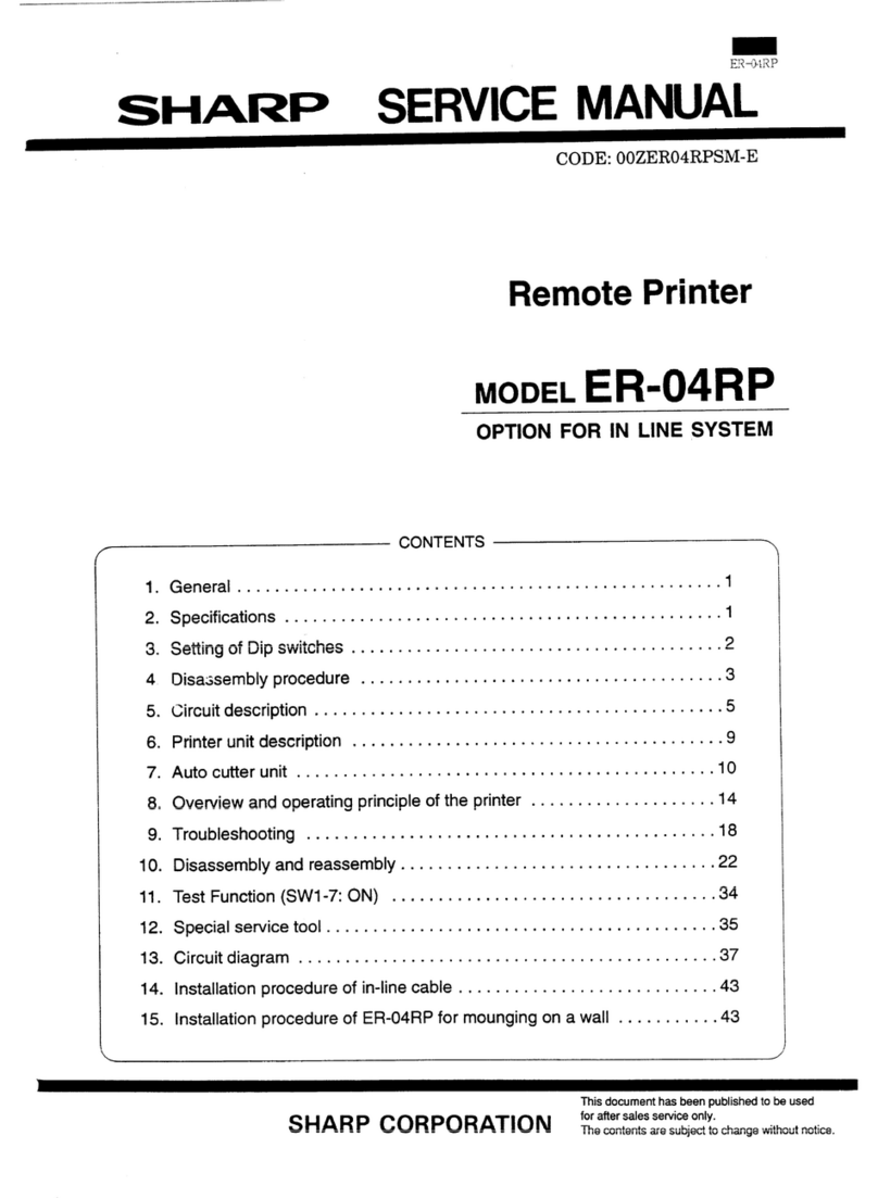
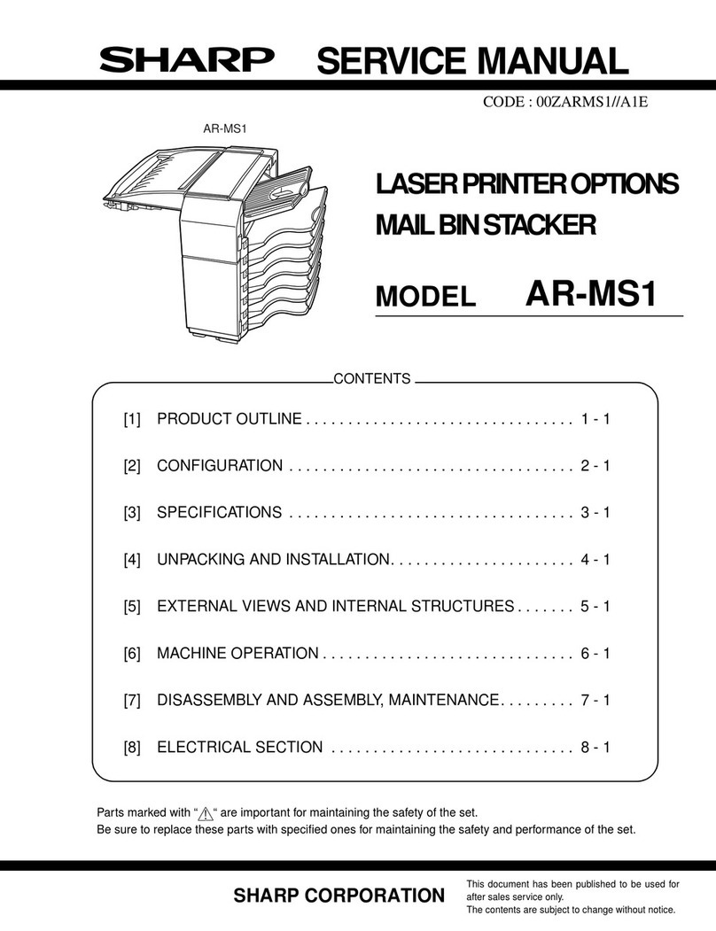
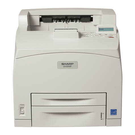
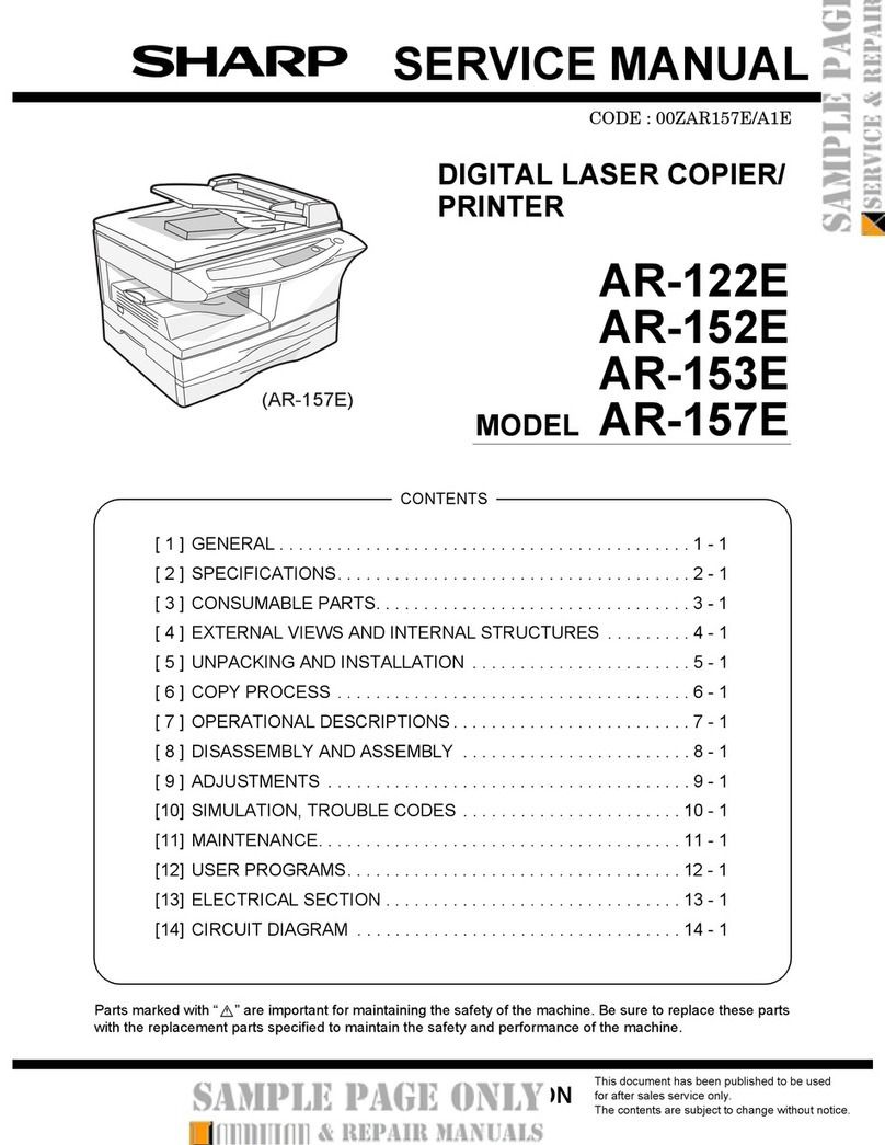
Sharp AR-D29 User manual

CODE : 00Z
qSERVICE MANUAL
CONTENTS
Parts marked with "!" are important for maintaining the safety of the set. Be sure to replace these parts with specified
ones for maintaining the safety and performance of the set.
SHARP CORPORATION This document has been published to be used
for after sales service only.
The contents are subject to change without notice.
ARD29//A1E
LASER PRINTER OPTIONS
PAPER FEED UNIT
MODEL AR-D29
[1] PRODUCT OUTLINE . . . . . . . . . . . . . . . . . . . . . . . . . . . . . . . . . 1 - 1
[2] CONFIGURATION . . . . . . . . . . . . . . . . . . . . . . . . . . . . . . . . . . . 2 - 1
[3] SPECIFICATIONS . . . . . . . . . . . . . . . . . . . . . . . . . . . . . . . . . . . 3 - 1
[4] UNPACKING AND INSTALLATION . . . . . . . . . . . . . . . . . . . . . . 4 - 1
[5] EXTERNAL VIEWS AND INTERNAL STRUCTURES . . . . . . . . 5 - 1
[6] ADJUSTMENTS . . . . . . . . . . . . . . . . . . . . . . . . . . . . . . . . . . . . . 6 - 1
[7] DISASSEMBLY AND ASSEMBLY, MAINTENANCE . . . . . . . . . 7 - 1
[8] BLOCK DIAGRAM, WIRING DIAGRAM,
CIRCUIT DIAGRAM, PARTS ARRANGEMENT. . . . . . . . . . . . . 8 - 1
PARTS GUIDE

AR-D29 PRODUCT OUTLINE
1 – 1
[1] PRODUCT OUTLINE
This unit is installed to one of the following machines to serve as a Paper feed module.
When installing one of the following machines, the stand with multi-purpose tray (AR-D29) must be installed in advance.
[2] CONFIGURATION
For combinations of options, refer to "C. List of combination of peripheral devices" described later.
Applicable models AR-M312U/AR-M420U
Upperexittray
(AR-TE4)
Finisher
(AR-FN6)
Mail-binstacker
(AR-MS1)
Standwithmultipurposedrawer
(AR-D29)
Scannerrack
(AR-RK2)
Saddlestitch
finisher
(AR-FN7)
Duplexmodule
(AR-DU3)
Duplexmodule/
bypasstray
(AR-DU4)
Exittray
(AR-TE3)
Rightupperexittray
(AR-TE5)
ScannermodulewithDSPF
(AR-EF6)
ScannermodulewithOC
(AR-EF5)
Punchunit
(AR-PN1A/B/C/D)
Power supply unit
(AR-DC1)

AR-D29 SPECIFICATIONS
3 – 1
[3] SPECIFICATIONS
Model name AR-D29
Type Stand with multi-purpose drawer
Transport speed To support 31-42 sheet/minute
Transport alignment Center alignment
Paper size A3, B4, A4, A4R, B5, B5R, A5R
11" x 17", 8.5" x 14", 8.5" x 13", 8.5" x 11",
8.5" x 11"R, 5.5" x 8.5"R
Executive, Japanese p/c, Monarch (envelope)
Com-10 (envelope), DL (envelope),
C5 (envelope), ISO B5 (envelope)
How to change
the paper size Guide adjustment by user/
Software setting by user
Factory default paper size setting A3
Media available for paper feeding Plain paper : 60-128g/m² / 16-34lbs
Index paper : 176g/m² / 47lbs
Cover paper: 200-205g/m² / 54-55lbs
Envelope : 75-90g/m², 20-24lbs
Transparency film
*Media heavier than 105g/m² should be A4/8.5 x 11" or smaller. Media heavier than 128g/m² should be fed
from shorter edge.
*Only single paper feed is enabled for overlay copy or copy on back-side of printed paper.
Paper capacity Standard: 500sheets (80g/m²)
Post card: 40sheets
Envelope: 40sheets
Transparency film: 40sheets
Paper type Plain, recycled, pre-printed, pre-punched, color, letter head, labels, heavy, transparency, Japanese p/c, envelope
(User can set bi-type for each of the above paper type.)
Sizes to be detected Auto detection-AB: A3, B4, A4, A4R, B5, B5R, 8.5"x13", A5R
Auto detection-Inch: 11" x 17", 8.5" x 14", 8.5" x 11", 8.5" x 11"R, 7.25" x 10.5"R, 5.5" x 8.5R
Manual (input detection):
postal card, Monarch (envelope), Com-10 (envelope), DL (envelope), C5 (envelope), ISO B5 (envelope)
Ignore detection selectable:
Paper balance detection Provided (paper empty and 3 steps)
Paper loading system To be loaded from the upper side with front loading system
Tray ascent/
descent time Ascent Within 7 seconds
At paper empty, required time from tray insert to the empty detection
Descent Own weight descent
Dehumidification heater Not provided
Power consumption 24.5W or lower
Power source Supplied from main unit (DC24V 1A / DC5V 0.1A)
External dimensions 589 x 630 x 404 (mm)
Occupied dimensions 963 x 665 (mm)
Weight Approx. 25.2kg
AR-D29 UNPACKING AND INSTALLATION
4 – 1
[4] UNPACKING AND INSTALLATION
<BEFORE INSTALLATION>
• Start installation after checking that the DATA and COMMUNICA-
TION indicators on the operation panel are neither lit nor blinking.
1) Turn off the main switch of the main unit of the printer.
Turn the main switch located on the front side of the printer to the
"OFF" position.
Then remove the power plug from the outlet.
2) Attach the adjusters and adjust them.
<1>Insert the left adjusters to the stand/paper drawer.
<2>Turn the each adjusters to lower them until they touch the floor.
*Be sure to attach the left adjuster to prevent overturning.
Caution: The lower tray cannot be pulled out unless the adjuster is low-
ered to the specified position.
3) Put the main unit of the printer on the stand/paper drawer.
<1>Pull out the paper tray of the main unit until it stops and then
remove it by lifting both ends of the tray.
<2>Hold the main unit of the printer at the positions shown in the illus-
tration and put the main unit on the stand/paper drawer so that the
front side and the left side of the main unit are aligned to those of
the stand/paper drawer.
Caution: For installation of the main unit, it must be held by two persons
and installed without haste.
4) Connect the main unit to the stand/paper drawer.
<1>Attach the rear mounting plates using a supplied screw for each.
Caution: Insert the rear mounting plates under the desk frame.
<2>Pull out the upper paper tray of the stand/paper drawer until it stops
and attach the front mounting plates using a supplied screw for each.
Then, remove the lock of the paper tray and close the tray.
<Parts included>
Left adjuster: 1 pc. Front mounting
plates: 2 pcs. Rear mounting
plates: 2 pcs. Screws (M4x6):
4 pcs.
"OFF"
12
2
2
2
Frontside
Rearside
Rear mounting plate
Rear mounting plate
Screw
Screw
Desk frame
Rear
mounting plate
Screw
Screw
Front
mounting plate
Front mounting
plate

AR-D29 UNPACKING AND INSTALLATION
4 – 2
<3>Reattach the paper tray of the main unit.
5) Connect the power supply I/F harness to the PCU PWB of the
main unit of the printer.
<1>Remove the screw that fixes the harness cover of the main unit of
the printer and slide the harness cover up to remove it.
Process the harness cover as shown in the illustration.
<2>Connect the connector of the relay harness of the multi purpose
drawer to the connector of the PCU PWB of the main unit of the printer.
<3>Reattach the power supply I/F harness cover to its original position
and fix it with the removed screw.
At this time, ensure that the power supply I/F harness are arranged
as shown in the illustration.
• Fix the harness securely to the wire saddle.
6) Attach the paper guides to the lower tray (large capacity tray) and
set the size.
Refer to "Setting and adjustment" described later.
*If another peripheral device must be installed, carry out the following
step at the end of the installation work.
7) Adjust the position of the paper guides of the upper paper tray of
the stand/paper drawer.
Refer to "Setting and adjustment" described later.
8) Carry out the off center adjustment.
Harness cove
r
Cut out.
Screw
CN10
Connector
Wire saddle
Harness cove
r
Screw
Wire saddle

AR-D29 EXTERNAL VIEWS AND INTERNAL STRUCTURES
5 – 1
[5] EXTERNAL VIEWS AND INTERNAL STRUCTURES
A. EXTERNAL VIEW
B. INTERNAL STRUCTURE
1
2
1 Multi-purpose tray (No. 2 tray) 2 Desk left door
2
1. MCPPD 5
34
6
1 Multi-purpose tray paper transport sensor (MCPPD) 4 Multi-purpose tray separation roller
2 Multi-purpose tray paper transport roller 5 Multi-purpose tray paper take-up roller
3 Multi-purpose tray paper feed roller 6 Multi-purpose tray

AR-D29 EXTERNAL VIEWS AND INTERNAL STRUCTURES
5 – 2
C. PWB, SENSOR
1.MCDRS
10.MCPWS
3.MCLUD
8.MCPED
2.MCSPD
12.MPTPWB
4.MCSS1
11.
5.MCSS2
7.MCSS4
6.MCSS3
9.MCPPD
No. Code Name Function Active condition Remark
1 MCDRS Side door open/close sensor Side door open/close detection H : Door closed
2 MCSPD MP tray remaining paper quantity sensor MP tray remaining paper quantity detection
3 MCLUD MP tray upper limit sensor MP tray upper limit detection H : Upper limit
detected
4 MCSS1 MP tray rear edge sensor 1 MP tray rear edge size detection L : When pressed In MP tray rear
edge size PWB
5 MCSS2 MP tray rear edge sensor 2 MP tray rear edge size detection L : When pressed In MP tray rear
edge size PWB
6 MCSS3 MP tray rear edge sensor 3 MP tray rear edge size detection L : When pressed In MP tray rear
edge size PWB
7 MCSS4 MP tray rear edge sensor 4 MP tray rear edge size detection L : When pressed In MP tray rear
edge size PWB
8 MCPED MP tray paper empty sensor MP tray paper empty detection L : Paper loaded
9 MCPPD MP transport sensor Detection of paper on the path L : Paper detected
10 MCPWS MP tray width sensor MP tray paper width detection Slide volume
11 MP tray rear
edge size PWB MP tray rear edge size PWB Multi-purpose tray rear edge size detection
12 MPTPWB MPT PWB
Distributed the power supply from the main
unit.

AR-D29 EXTERNAL VIEWS AND INTERNAL STRUCTURES
5 – 3
D. MOTOR, CLUTCH
2.MCLUM
3.MCPCL
4.MCM
1.MCFCL
No. Code Name Function Remark
1 MCFCL Multi-purpose transport clutch Clutch for transport from LCC desk
2 MCLUM Multi-purpose tray lift-up motor Multi-purpose tray lift-up
3 MCPCL Multi-purpose paper feed clutch Clutch for paper feed from Multi-purpose tray
4 MCM Multi-purpose transport motor LCC desk paper transport

AR-D29 ADJUSTMENTS
6 – 1
[6] ADJUSTMENTS
1. CHANGING THE PAPER SIZE
[Upper tray]
• A3 to A5R (11 x 7 to 5-1/2 x 8-1/2R) size plain paper can be set.
• Special paper can be set.
• Two maximum height lines are indicated: one for plain paper and one
for special paper.
Use the following procedure to change the size as needed.
1) Pull out paper tray.
If paper remains in the tray, remove it.
2) Adjust the guide plates A and B in the tray to the length and width of
the paper.
The guide plates A and B are slidable. Adjust them to the paper size
to be loaded while squeezing their lock levers.
3) Load paper into the tray.
Do not exceed red line when loading special paper to upper tray.
4) Gently push tray into the machine.
Push the tray firmly all the way into the machine.
5) Set the paper size.
Be sure to set the paper size and paper type referring to "2.Setting
the paper type and paper size".
If this is not done, paper misfeeds will occur.
2. SETTING THE PAPER TYPE AND
PAPER SIZE
Follow these steps to change the paper type setting if the paper type is
changed in either paper tray. For the paper types that can be used in
each tray.
1) Press the [CUSTOM SETTINGS] key.
The custom setting menu screen will appear.
2) Touch the [PAPER TRAY SETTINGS] key.
The paper tray selection screen will appear.
3) Touch the [TRAY SETTINGS] key.
4) Display the setting screen of the desired paper tray.
Touch the key or key to display the setting screen of the
desired paper tray.
Note: To automatically switch to a tray with the same size and type of
paper (if there is one) in the event that the paper tray runs out of
paper, display the last screen with the key and select [AUTO
TRAY SWITCHING].
5) Touch the [TYPE/SIZE] key.
6) Select the type of paper that was loaded in the tray.
Example: The paper type of tray 2 is selected
Touch the desired paper type to select it.
The paper size setting screen will appear.
PAPER TRAY
SETTINGS
TA
ORWARD
RINT
PRINTER
CONDITION
TRAY SETTINGS
PAPER TRAY SETTINGS
CUSTOM SETTINGS
1/4
PLAIN / A4
OK
PRINT
PAPER TRAY SETTINGS
TYPE / SIZE
CUSTOM SETTINGS
TRAY 1
FAX I-FAX
COPY
DOC.
FILING
FIXED PAPER SIDE
DISABLE DUPLEX
DISABLE STAPLE
DISABLE PUNCH
TYPE / SIZE
TRAY 2
PER TRAY SETTINGS
PRINT
COPY
I-FAX DOC.
FILING
FAX
PLAIN / A4
CANCEL
1/2
PLAIN
RECYCLED
PRE-PRINTED PRE-PUNCHED
LETTER HEAD
COLOUR
HEAVY PAPER ENVELOPE
LABELS
TRANSPARENCY
TRAY 2 TYPE/SIZE SETTING
SELECT THE PAPER TYPE.
CUSTOM SETTINGS
1/2

AR-D29 DISASSEMBLY AND ASSEMBLY, MAINTENANCE
7 – 1
[7] DISASSEMBLY AND ASSEMBLY, MAINTENANCE
A. MAJOR PARTS AND SIGNAL FUNCTIONS
Code Name Function Remark
MCDRS MP door open / close sensor MP left door open / close detection
Control PWB Control PWB Communication with the machine,
machine operation control
MCSPD MP tray remaining paper quantity sensor MP tray remaining paper quantity detection
MCLUD MP tray upper limit sensor MP tray upper limit detection
MDSS1 MP tray rear edge sensor 1 MP tray rear edge size detection In MP tray rear edge size PWB
MCSS2 MP tray rear edge sensor 2 MP tray rear edge size detection In MP tray rear edge size PWB
MCSS3 MP tray rear edge sensor 3 MP tray rear edge size detection In MP tray rear edge size PWB
MCSS4 MP tray rear edge sensor 4 MP tray rear edge size detection In MP tray rear edge size PWB
MCPED MP tray paper empty sensor MP tray paper empty detection
MCPPD MP transport sensor Detection of paper on the path
MCPWS MP tray width sensor MP tray paper width detection Slide volume
MP tray rear
edge size PWB MP tray rear edge size PWB MP tray rear edge size detection
MCFCL Multi-purpose tray transport clutch Multi-purpose tray transport clutch
MCLUM Multi-purpose tray lift-up motor Multi-purpose tray lift-up
MCPCL Multi-purpose paper feed clutch Clutch for paper feed from Multi-purpose tray
MCM Multi-purpose tray transport motor Multi-purpose tray paper transport
MCM
MCM
MCM
MCDRS
MCSPD
MCSPD
MCSPD MCLUD
MCPED
MCSS2
MCSS4
MCSS1
MCSS3
MCSS3
MCSS3
MCPPD
MCPWS
MCPWS
MCPWS
MCLUM
MCLUM
MCLUM
MCFCL
MCFCL
MCFCL
MCPCL
MCPCL
MCPCL
MPT LD PWB
MPT PWB
12
4
7
11
5
10
3
6
1
9
2
8
+5V
MCPWS
+5V
MCPPD
+5V
CN-E
+5V
VAREF
MCPED
N.C.
MCPWS2
MCLUD
14
13
+5V
MCDRS
MCSPD
PHDR-14VS-1
3
1
2
5
MCSS2
8
MCSS1
6
4
7
9
10
GND2
GND2
GND2
CN-F
MCSS3
MCSS4
11
12
GND2
GND2
GND2
GND2
GND2
PHDR-12VS-1
24V 1
MCLUM/ 2
PHR-2
MCPCL/
+24V
MCFCL/
+24V
3
1
MCM/
GND1
+24V
MCM-T
2
5
4
MCMCLK/
6
7
8
9
PHR-9
11
22
11
22
SMR-02V-B
SMR-02V-NSMP-02V-NC
SMP-02V-BC
SRA-21T-4
MCLUM/
24V
MCSS2
MCSS3
MCSS4
N.C.
MCSS1
GND2
PHR-6
PHR-2
5
2
6
4
3
1
MCMCLK/
MCM/
4
GND1
3
1
MCM-T
5
+24V
2
PHR-5
13
14
17
18
15
16
18
15
13
16
17
14
SMP-03V-BC SMR-03V-B
GND2
1
MCLUD
MCPPD
2
2
+5V
3
+5V
3
GND2
1
1
2
3 GND2
MCSPD
+5V
2
1
CN-D
CN-A
8
4
5
8
6
9
6
9
7
5
4
7
SMR-18V-BSMP-18V-BC
3
2
1
2
3
1
GND23
GND23
MCPED
+5V
1
MCDRS
1
2
+5V
2
3T
MCPWS2
MCPWS
VAREF
2T
1T

AR-D29 DISASSEMBLY AND ASSEMBLY, MAINTENANCE
7 – 2
B. MAINTENANCE LIST
(1) MAINTENANCE LIST
*1:Replacement reference: Use the counter value of each paper feed port as the replacement reference.
Paper feed section pickup roller, paper feed roller: 100K or 1 year
uCheck (Clean, replace, or adjust as necessary.) FClean bReplace vAdjust ,Lubricate kMove position
Unit name
No.
Part name When
calling 100K 200K 300K 400K Remark
Paper feed separation section 1 Paper feed rollers uuuuu*1
Transport section 2 Transport rollers uFFFF
Drive section 3 Gears u,,,,(Specified position)
4Belts uuuuu
Other 5 Sensors uuuuu
4
5
5
1
3
5
1
5
2
4

AR-D29 DISASSEMBLY AND ASSEMBLY, MAINTENANCE
7 – 3
(2) MAINTENANCE AND PARTS REPLACEMENT
(List of Replacement Parts)
a. Paper feed unit
1) Pull out the multi-purpose tray.
First, pull out the right side of the tray, and then pull out the left side.
2) Remove the left door.
3) Remove the multi-purpose paper feed unit.
a-1. Pick up roller
a-2. Paper feed roller
a-3. Separate roller
a-4. Torque limiter
1) Pull out the multi-purpose tray.
2) Remove the paper guide.
No. Unit Parts
a Paper feed unit 1 Pick up roller b
2 Paper feed roller b
3 Separate roller b
4 Torque limiter u
5Belts u
6 Upper limit sensor u
7 Paper empty sensor u
8 Paper transport sensor u
9 Side door open/close sensor u
10 Transfer rollers u
b Multi-purpose
drive unit 1 Gears u,
c Other 1 Rear edge size PWB
2 Remaining paper quantity sensor u
a-1
a-8
c-1
a-2
a-7
a-6
a-10
a-9
a-4
a-5
c-2
a
a-10
a-5
a-3
b-1
b
1)
2)
2)
1)
6)
4)
5)
4)
1)
2) 3)
1)

AR-D29 DISASSEMBLY AND ASSEMBLY, MAINTENANCE
7 – 4
3) Disengage the roller hook, and remove the roller.
*When installing the roller, check to ensure that the hook is securely
engaged in the groove.
4) After removing the roller, remove the torque limiter.
*When installing the torque limiter, check to ensure that the pin is
fully inserted into the torque limiter groove.
a-5. Belts
1) Remove the paper feed unit.
2) Remove the pickup roller and paper feed roller.
a-6. Upper limit sensor
a-7. Paper empty sensor
a-8. Paper transport sensor
a-9. Side door open/close sensor
1) Remove the paper feed unit.
a-10. Transfer rollers
1) Remove the paper feed unit.
a
1)
ba
a
a
1)
1)
1)
1)
2)
3)
4) 3)
3)
4)
4)
a
a
b b
a
b

AR-D29 DISASSEMBLY AND ASSEMBLY, MAINTENANCE
7 – 5
b. Multi-purpose drive unit
1) Remove the rear cabinet.
2) Remove the multi-purpose tray drive section.
b-1. Gears
1) Remove the multi-purpose tray drive section.
c-1. Rear edge size PWB
c-2. Remaining paper quantity sensor
1) Remove the rear cabinet.
2) Remove the control PWB and the sensors.
2)
1)
1)
3)
2)
2)
1)
2)
1)
1)
a
a
2)
2)
1)
1)

AR-D29 BLOCK DIAGRAM, WIRING DIAGRAM,CIRCUIT DIAGRAM, PARTS ARRANGEMENT
8 – 1
[8] BLOCK DIAGRAM, WIRING DIAGRAM,CIRCUIT DIAGRAM, PARTS ARRANGEMENT
A. BLOCK DIAGRAM
A
B
C
D
87654321
12345678
D
C
B
A A
B
C
D
87654321
12345678
D
C
B
A A
B
C
D
87654321
12345678
D
C
B
A A
B
C
D
87654321
12345678
D
C
B
A
1/1
MCDRS
VD/S-GND
PRINTER
MALTI CS UNIT
+5V1(VD)
GND2(P-GND)
MCFCL/
MCLUM/
MCPCL/
Multi PWB
+24V2(VB)
VAREF
MCPPD
MCDRS
MCPED
MCLUD
MCPWS
MCPWS
MCDRS
MCPPD
VD/S-GND
VD/S-GND
MCLUD
DCPR/
MCSPD
MCSET
MCSS1
MCSS2
MCSS3
MCSS4
GND1(S- GND)
MCM-T
MCMCLK/
MCM/
MCPPD
MCLUD
MCSPD
VD/S-GND
VD/S-GND
MCPEDMCSPD
MCPED
S-GND
MCSS1MCSS1
S-GND
MCSS2 MCSS2
S-GND
MCSS3MCSS3
MCSS4
MCSS4
S-GND
MCPWS
VAREF
MCFCL/
DCPR/
VB
MCMCLK/
MCFCL/
MCPCL/
MCM
MCM-T
VB
MCLUM/
MCM/
MCPCL/
P-GND
VB/P-GND
MCLUM/
DH MPF
DHPWB ACL
AC N
AC N
ACL
MCSET MCSET
S-GND
OPTIONALY
VB
DH-SW

AR-D29 BLOCK DIAGRAM, WIRING DIAGRAM,CIRCUIT DIAGRAM, PARTS ARRANGEMENT
8 – 2
B. WIRING DIAGRAM
A
B
C
D
87654321
12
3
456
7
8
D
C
B
AA
B
C
D
87654321
12
3
456
7
8
D
C
B
AA
B
C
D
87654321
12
3
456
7
8
D
C
B
AA
B
C
D
87654321
12
3
456
7
8
D
C
B
A
1/1
AC L1
2N.C
15
12
9
6
3
17
14
11
8
5
2
16
13
10
7
4
1
18
19
20
24
23
22
21
GND1
+5V
GND2
VAREF
MCPPD
MCDRS
MCPED
MCLUD
MCPWS
MCSS4
MCSS1
MCSS2
MCSS3
MCSPD
MCSET
MCPCL/
MCFCL/
MCLUM/
MCM-T
MCMCLK/
MCM/
e/?
DCPR/
12
MCSS4
4
17 MCPCL/
11
MPT
PWB
3
MCMCLK/
GND1
1
5
7
MCPED
MCPCL/
16
11
MCSS3
5
10
MCSET
4
MCM-T
24
18
12
MCPCL
N.C
MCDRS
+24V
22
20
6
10
MCSS2
3
3
MCSPD
2
14
MCLUM/
VAREF
6
8
MCSS1
MCPPD
1
2
9
MCPWS
MCFCL/
13
DCPR/
2
7
MCFCL/
+5V
1
15
MCFCL
MCM/
GND2
23
19
9
8
MCLUD
+24V
21
2
1MCLUM
LIFT MOTOR UNIT
3DCPR/
+24V2
1N.C
2
1
GND1
MCLUM
+24V
+24V
1
12
2
1
12
2
5
MCSS2
8
MCSS1
6
4
7
9
10
+5V
MCPWS
+5V
MCPPD
+5V
GND2
MCLUM 1
GND1 2
MCMCLK/
MCM/
4
GND1
3
1
MCM
MCM-T
5
+24V
2
3
1
MCM/
GND1
+24V
MCM-T
2
5
4
MCMCLK/ 6
7
8
9
+24V
DCPR/
+5V
VAREF
MCPED
N.C.
MCPWS2
GND2
GND2
MCLUD
14
13
+5V
MCDRS
MCSS3
MCSS4 11
12
GND1
GND2
GND2
GND2
GND2
MPT LD PWB
5
2
6
MCSS2
4MCSS3
3
MCSS4
1N.C.
MCSS1
GND2
8
4
GND2
13
5
MCDRS
3
8
1
2
GND2
1
14
3
MCLUD
3
MCPPD
17
GND2
MCSPD
2
18
6
MCSPD
MCPED
9
+5V
3T
+5V
1
6
MCPWS2
MCDRS
2
9
MCLUD
1
+5V
15
MCPWS
MCPPD
16
18
VAREF
3
7
5
2T
+5V
15
4
PAPER FEEDING UNIT
2
7
MPT VR UN
MCPED
3
13
1T
+5V
2
GND2
16
1
17
14
3
2
12
3
1
GND2
PHDR-24VS-1
MCSPD
PHDR-14VS-1
PHDR-12VS-1
PHR-2
SMR-18V-B
SMP-18V-BC
SMP-03V-BC SMR-03V-B
PHR-6
PHR-2
PHR-5
PHR-9
SMR-02V-B
SMR-02V-NSMP-02V-NC
SMP-02V-BC
PHR-3
SRA-21T-4
1
12
2
ELR-02VF
AC N 3
2AC N
AC L
1
3N.C
PHR-3 B2P3-VH
B2P3-VH
CN-BCN-C
CN-A
N.C
3
DHPWB
ELP-02
DH MPF
TIGER MAIN UN
ELP-04NV
RES_FIN1
RXD_FIN2/
2
4
TXD_DSK
GND2
2
(N.C)
2
GND
19
14
ELR-02VF
B22B-PADRS
RES_DSK
1
3
GND
13
3
2
RXD_DSK
18
5
GND2
4
PADP-22V-1-R
2
RXD_FIN1/
+24V4
+5V2
TXD_FIN1
TXD_FIN2
15
8
DCPS
RES_FIN2 10
3
TRC_DSK/
11
7
DTR_FIN2/
ELP-02V
1
16
DTR_FIN1/ 4
DSR_FIN1/
1
1
2
5
DTR_DSK
17
9
6
1
4
DSR_FIN2/
12
ELR-04V
CN11
FGS_FIN/
3
1
GND
21
20
(N.C)
(N.C)
DSR_DSK
22 RXD-DSK/ 6
9
RES-DSK
1
GND2 4
DSR-DSK/
7
10
TRC-DSK
P-GND 2
TXD-DSK 5
8
DTR-DSK/
11
S-GND
3
VD(+5V)
+24V(VB)
CN10
B24B-PADES PADP-24V-1-E
FUSEPWB
DH-SW
CN-B
CN-C
CN-F
CN-E
CN-D
CN-A
POWERSUPPLY I/F UN
OPTION
(OPTION FOR JAPAN)
(OPTION FOR JAPAN)

AR-D29 BLOCK DIAGRAM, WIRING DIAGRAM,CIRCUIT DIAGRAM, PARTS ARRANGEMENT
8 – 3
C. CIRCUIT DIAGRAM
A
B
C
D
87654321
12345678
D
C
B
A A
B
C
D
87654321
12345678
D
C
B
A A
B
C
D
87654321
12345678
D
C
B
A A
B
C
D
87654321
12345678
D
C
B
A
1/1
MPT PWB
M
CND-2
VD
VB
VB
CNC-1 +5V1
CNC-2 VAREF
CNC-3 +24V2
CNC-4 GND1
CNC-5 GND2
CNC-6 MCPPD
CNC-7 MCDRS
CNC-8 MCPED
CNC-9 MCLUD
CNC-10 MCPWS
CNC-12 MCSS2
CNC-13 MCSS3
CNC-14 MCSS4
CNC-24 DCPR/
CNC-15 MCSPD
CNC-16 MCSET
CNC-17 MCPCL/
CNC-18 MCFCL/
CNC-19 MCLUM/
CNC-20 MCM-T
CNC-21 MCMCLK/
CNC-22 MCM/
CNC-11 MCSS1
CND-9
MCPCL/
CND-7
MCFCL/
CNE-9
MCPWS
CNE-6
VAREF
CNE-13
MCLUD
CNE-12
MCPED
CNE-10
MCPPD
CNA-2
GND1 CND-3
MCM/
CND-4
MCM-T
CNF-1,3,4,5,6,7,8
GND2
CNE-14
MCSPD
CNB-2
DCPR/
CNF-12
MCSS4
CNF-11
MCSS3
CNF-10
MCSS2
CND-5
MCMCLK/
CNE-11
MCDRS
CNF-9
MCSS1
C004
223Z/50V
C003
47u/35V
+
C002
223Z/50V
C001
47u/35V
+
C005
47u/35V
+
C006
223Z/50V
CNE-1,2,3,4,5
+5V1
CND-1,6,8
CNB-1
+24V2
JP001
GND
CNC-23 N.C
CNE-8
MCPWS2
CND-2
R002
2.4kJ1/2W
TR001
2SB1240
2.4kJ1/4W
R001
2.4kJ1/2W
R004
TR002
2SB1240
2.4kJ1/4W
R003
D001
DSM1D
CNF-2
D003
1SS133
D002
1SS133
ICP001
ICP-N20
JP002
(MCLUM)
CNA-1
MCLUM
Parts View
CN-A
CN-B
CN-D CN-C
CN-E
CN-F
CN-A
CN-C
CN-D
CN-E
CN-F
CN-B
(JST:B2B-PH-K-S) (JST:B3B-PH-K-S)
2
3
1
1DCPR/
+24V2
N.C
MCLUM
2GND1
(JST:B24B-PHDSS-B)
12
4
6
8
10
12
14
16
18
20
22
24
3
5
7
9
11
13
15
17
19
21
23
+5V1
+24V2
GND2
MCDRS
MCLUD
MCSS1
MCSS3
MCSPD
MCPCL/
MCLUM/
MCMCLK/
N.C
VAREF
GND1
MCPPD
MCPED
MCPWS
MCSS2
MCSS4
MCSET
MCFCL/
MCM-T
MCM/
DCPR/
(JST:B9B-PH-K-S)
1
2
3
4
5
6
7
8
9
+24V2
GND1
MCM/
MCM-T
MCMCLK/
+24V2
MCFCL/
+24V2
MCPCL/
(JST:B14B-PHDSS-B)
1
3
5
7
9
11
13
2
4
6
8
10
12
14
+5V1
+5V1
+5V1 +5V1
+5V1
VAREF
MCPWS2
MCPPD
MCPED
MCSPD
N.C
MCPWS
MCDRS
MCLUD
(JST:B12B-PHDSS-B)
1
3
5
7
9
11
2
4
6
8
10
12
GND2
GND2
GND2
GND2 GND2
GND2
GND2
GND2
MCSS1
MCSS3 MCSS2
MCSS4

AR-D29 BLOCK DIAGRAM, WIRING DIAGRAM,CIRCUIT DIAGRAM, PARTS ARRANGEMENT
8 – 4
D. PARTS ARRANGEMENT
■ CONTROL PWB

qPARTS GUIDE
CONTENTS
MODEL AR-D29
1 Exteriors
2 Left door
3 Frame 1
4 Frame 2
5 Tandem cassette
6 Multi paper feed
7 Multi drive
8 500 cassette[Multi purpose]
9 Packing Material & Accessories
■Index

– 1 –
DEFINITION
The definition of each Rank is as follows and also noted in the list
Rank A : Maintenance parts, and consumable parts which are not included in but closely related to maintenance parts
Rank B : Performance/function parts (sensors, clutches, and other electrical parts), consumable parts
Rank E : Unit parts including PWB
Rank D : Preparation parts (External fitting, packing, parts packed together)
Rank C : Parts other than the above (excluding sub components of PWB)
Because parts marked with "!" is indispensable for the machine safety maintenance and operation, it must be replaced with
the parts specific to the product specification.
FOther than this Parts Guide, please refer to documents Service Manual(including Circuit Diagram)of this model.
FPlease use the 13 digit code described in the right hand corner of front cover of the document, when you place an order.
FFor U.S. only-Use order codes provided in advertising literature. Do not order from parts department.
1Exteriors
2Left door
NO. PARTS CODE PRICE
RANK
NEW
MARK
PART
RANK DESCRIPTION
1GCAB-0953FCN2 BM D Top side cabinet
2XHBS740P10000 AA C Screw(4×10)
4XHBS740P06000 AA C Screw(4×6)
5GCAB-0955FCN2 BR D Desk right cabinet
6PCOVP1796FCNZ AQ D Adjuster cover N
7GCAB-0975FCN3 BD D Desk front lower cabinet
8GCAB-0954FCN1 AY D Tandem left front cabinet
9GCAB-0958FCN2 BA D Desk left lower cabinet
10 GCAB-0957FCN1 BA D Desk left rear cabinet
11 GCAB-0974FCN1 AY D Desk side rear cabinet
12 GCAB-0956FCN5 BU D Desk rear cabinet
13 PCOVP1586FCNZ AR D AC inlet cover
14 XEBS730P10000 AC C Screw(3×10)
NO. PARTS CODE PRICE
RANK
NEW
MARK
PART
RANK DESCRIPTION
1GDOR-0033FCNZ BP D Desk left door
3NSFTZ2635FCZZ AX C Desk left door lock shaft
4PTME-0284FCZZ AE C Desk left door lock pawl
5LX-BZ3006SC0M AA C Screw(3×6)
6MLEVP0818FCN3 AN C Desk left door cancellation lever
10 XEBS740P12000 AA C Screw(4×12)
11 XWHSD40-08120 AA C Washer
12 MSPRC2916FCZZ AC C Desk left door lock spring
13 PG DM1944FCZ1 BH D Desk left door PG
Table of contents
Other Sharp Printer manuals

Sharp
Sharp MX-C400P User manual

Sharp
Sharp AR-215 User manual

Sharp
Sharp JX-8200 User manual

Sharp
Sharp MX-C380P User manual

Sharp
Sharp AJ-2200 Manual instruction

Sharp
Sharp MX-M450NA Instruction Manual

Sharp
Sharp SF-7300 User manual

Sharp
Sharp AR-C200P - Color Laser Printer User manual

Sharp
Sharp ER-01PU User manual

Sharp
Sharp FO 4400 - B/W Laser - All-in-One User manual

Sharp
Sharp AR-C260P User manual

Sharp
Sharp AR-235 User manual

Sharp
Sharp AJ-2200 Setup guide

Sharp
Sharp JX-9400 User manual

Sharp
Sharp MX-M350-U User manual

Sharp
Sharp JX-735 User manual

Sharp
Sharp AR-C200P - Color Laser Printer User manual

Sharp
Sharp ER-A440 User manual

Sharp
Sharp MX-B468P User manual

Sharp
Sharp MX-M260 Setup guide