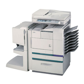
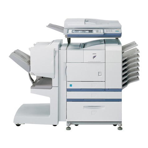
Sharp AR-M208 User manual

SERVICEMANUAL
CODE: 00ZARM208/A1E
DIGITALLASERCOPIER/
PRINTER
(For U.S.A)
MODEL AR-M208
CONTENTS
ThisServiceManualdescribesonly thedifferencesfrom00ZAR275//A1E.
The items whicharenotdescribedinthisManualarecommonwiththe
00ZAR275//A1E.
[1]NOTEFORSERVICING........... . .... . .............. ..1-1
[2]SYSTEMCONFIGURATION. .. ....... .. .. . . ... . .........2-1
[3]SPECIFICATIONS........... .......... .. .. ......... . ..3-1
[4]CONSUMABLEPARTS..... . .... ...... . ....... ...... . ..4-1
[5]UNPACKINGANDINSTALLATION..... ... . . .. ... ....... ..5-1
[6]EXTERNAL VIEWAND INTERNALSTRUCTURE... ..... .. . .6-1
[7]ADJUSTMENTS, SETTING.... ... ........... .. ... .. . .. ..7-1
[8]SIMULATION.... ........... ... ...... . ........... .....8-1
[9]TROUBLE CODELIST.. ........ . ....... .............. ..9-1
[10]DISASSEMBLY,ASSEMBLYANDMAINTENANCE..... . .... 10-1
[11]OTHERS... ......... .......... . . ..... ............... 11-1
Partsmarkedwith “ ”are importantformaintainingthesafety oftheset. Besure to replace these partswith
specifiedonesfor maintainingthesafetyand performance of the set.
SHARPCORPORATION Thisdocumenthasbeen publishedto beused
forafter sales service only.
Thecontentsaresubjecttochange withoutnotice.

Thisproductisaclass1laserproductthatcomplieswith21CFR1040.10and1040.11oftheCDRHstandardandIEC825. Thismeans thatthis
machinedoesnotproduce hazardouslaser radiation. Theuseofcontrols,adjustmentsorperformanceofproceduresotherthanthose specified
hereinmayresultinhazardousradiation exposure.
Thislaserradiationisnotadangertotheskin,but when anexactfocusingofthelaserbeamisachievedontheeye’sretina,thereisthedangerofspot
damagetotheretina.
Thefollowing cautionsmustbeobservedtoavoid exposureofthe laserbeam toyoureyes atthe time ofservicing.
1)When a probleminthelaseroptical unithasoccurred, thewhole opticalunitmustbeexchanged as aunit,notasindividualparts.
2)Do notlookintothemachinewiththemain switch turnedonafterremovingthedeveloperunit,tonercartridge, anddrumcartridge.
3)Donotlookintothelaserbeam exposureslitofthelaseropticalunitwiththe connectorconnectedwhenremovingandinstalling theoptical
system.
4)Themiddleframecontains thesafetyinterlockswitch.
Donotdefeatthe safetyinterlockbyinsertingwedgesorotheritemsintotheswitchslot.
CAUTION
Warning!
Thisproduct isaclass Aproduct.
Ifitisoperated inhouseholds, offices or similarsurroundings,itcan produce radiointerferencesat other
appliances,sothatthe user has totakeadequatecountermeasures.
CLASS 1LASERPRODUCT
LASERKLASSE1
LUOKAN 1LASERLAITE
KLASS 1LASERAPPARAT
VAROITUS!
LAITTEENKÄYTTÄMINENMUULLAKUINTÄSSÄ
KÄYTTÖOHJEESSA MAINITULLATAVALLASAATTAA
ALTISTAAKÄYTTÄJÄNTURVALLISUUSLUOKAN1
YLITTÄVÄLLENÄKYMÄTTÖMÄLLE
LASERSÄTEILYLLE.
VARNING
OMAPPARATENANVÄNDS PÅANNAT SÄTTÄNI
DENNABRUKSANVISNING SPECIFICERATS,KAN
ANVÄNDARENUTSÄTTASFÖR OSYNLIG
LASERSTRÅLNING,SOMÖVERSKRIDERGRÄNSEN
FÖRLASERKLASS1.
CAUTION
INVISIBLELASERRADIATION,
WHEN OPEN ANDINTERLOCKS DEFEATED.AVOID
EXPOSURETO BEAM.
VORSICHT
UNSICHTBARE LASERSTRAHLUNG,
WENN ABDECKUNGGEÖFFNETUND
SICHERHEITSVERRIEGELUNG ÜBERBRÜCKT.NICHT
DEMSTRAHL AUSSETZEN.
VARO !
AVATTAESSA JASUOJALUKITUS OHITETTAESSAOLET
ALTTIINA NÄKYMÄTTÖMÄLLELASERSÄTEILYLLE ÄLÄ
KATSOSÄTEESEEN.
ADVARSEL
USYNLIGLASERSTRÅLNINGVED ÅBNING,NÅR
SIKKERHEDSBRYDEREER UDE AF
FUNKTION.UNDGÅUDSAETTELSEFOR
STRÅLNING.
VARNING!
OSYNLIGLASERSTRÅLNING NÄRDENNADELÄR
ÖPPNAD OCHSPÄRRENÄR URKOPPLAD.BETRAKTAEJ
STRÅLEN.–STRÅLENÄR FARLIG.
CLASS1
LASER PRODUCT
LASER KLASSE1
Disconnectthe ACcord before servicing theunit.
LASERWAVE–LENGTH: 795 ± 15 mm
Pulse times: 0.481 ms/6mm
Outputpower:5mW
CAUTION
VORSICHT
ADVARSEL
ADVERSEL
VARNING
VARO!
INVISIBLELASERRADIATION WHEN OPENANDINTERLOCKSDEFEATED.
AVOIDEXPOSURE TOBEAM.
UNSICHTBARELASERSTRAHLUNG,WENN ABDECKUNGGEÖFFNET UND
SICHERHEITSVERRIEGELUNGÜBERBRÜCKT.NICHTDEM STRAHLAUSSETZEN.
USYNLIGLASERSTRÅLNINGVED ÅBNING, NÅRSIKKERHEDSBRYDEREER
UDE AFFUNKTION. UNDGÅ UDSAETTELSEFOR STRÅLNING.
USYNLIGLASERSTRÅLING NÅRDEKSEL ÅPNES OG SIKKERHEDSLÅSBRYTES.
UNNGÅEKSPONERING FORSTRÅLEN.
OSYNLIGLASERSTRÅLNINGNÄR DENNADEL ÄR ÖPPNAD OCHSPÄRREN ÄR
URKOPPLAD.BETRAKTA EJSTRÅLEN.–STRÅLENÄRFARLIG.
AVATTAESSAJASUOJALUKITUSOHITETTAESSA OLET ALTTIINA NÄKYMÄTTÖMÄLLE
LASERSÄTEILYLLE ÄLÄ KATSO SÄTEESEEN.
Laserstrahl
I
TheAR-M208isamodified versionoftheAR-235/275,andisprovidedwiththeRSPFand theGDIprinterfunction.(ForcontentsoftheRSPF,refer
totheAR-RP3ServiceManual.)
Thedifferentpointsof theAR-M208fromtheAR-235/275areshowninthetablebelow.
AR-235/275 AR-M208
Item Page Content Contentofchange Remarks
[1] NOTEFORSERVICING Nochange
[2] SYSTEMCONFIGURATION
2-1 1.Structure
Block diagram
Blockdiagramischanged. Refer to page2-1,2ofthe
appendix.
2-2 2.Systemoutline(Options) Main unit
AR-235/275ischangedintoAR-M208
Options
AR-RP3isprovidedasa standard equipment.
AR-VR3,AR-SP4is deleted.
AR-D11 ischangedintoAR-D11N.
AR-D12 ischangedintoAR-D12N.
AR-FN5 ischangedintoAR-FN5N.
[3] SPECIFICATIONS
3-1 2.-B.-(2)Picturequalitymode Super Photo modeisdeleted. Refer topage 3-1 –4of
theappendix.
2.-B.-(3)Copymagnificationratio SPFisdeleted.
FixedmagnificationmodeofRSPFischanged.
1200dpimodeisdeleted.
2.-B.-(4)-b.Multicopy speed(sheets/
minute)
Change
3-2 2.-B.-(6)- a.Imageprocess SuperPhoto mode isdeleted.
2. -B.-(6)-d.Resolution Change(Pseudoresolutionisdeleted.)
3-3 3.-C.-(6)Scanningspeed 1200dpiis deleted.
3. -E.Imageprocess section Imaging speedof1200dpiis deleted.
TonerLifeis changed.
3-4 6.“Sharp PrinterLanguagewith Compression
(SPLC)”Printermode
“SharpPrinterLanguagewithCompression
(SPLC)”Printermodeisadded.
[4] CONSUMABLE PARTS MaintanceKits changed.
[5] UNPACKING AND INSTALLATION Nochange
[6] EXTERNALVIEW ANDINTERNALSTRUCTURE
6-1 1.External view Platencover(optional) ischangedintoRSPF
Added (Dehumidificationheaterswitch)
Referto page 6-1–2of
theappendix.
6- 4 5.Sensor Change (Abbreviationcode is added/change.)
[7] ADJUSTMENTS,SETTING
7-2 2.-A.-(3)Developingbiasvoltageadjustment
(SIM8-1)
Defaultof SUPERPHOTOof"5:Super"inthe
tableofAdjustmentspecificationischangedto
disabled.
Refer toSIM8-1,2,and
SIM8-3on page8-1,2of
the appendix.
2.-A.-(4)Gridbias voltageadjustment
(Highmode)(SIM8-2)
2.-A.-(5)Gridbias voltageadjustment
(Lowmode)(SIM8-3)
2.-B.-(2)Printstartposition adjustment Sim50-5 Modulationmeansforcompulsory
specificationoftrayareadded.
(Remark)
RefertoSIM50-5 onpage
8-10 ofthe appendix.
7-3 2.-B.-(5)Paperoffcenteradjustment Sim50-10Modulation means forcompulsory
specificationoftrayareadded.
(Remark)
RefertoSIM50-10on
page8-11 of the
appendix.
2. -B.-(6)Leftedgevoidarea adjustment Sim50-1 Modulationmeans forcompulsory
specificationoftrayareadded.
(Remark)
RefertoSIM50-1 onpage
8-10 ofthe appendix.
7- 9 (16) SPFscan position autoadjustmentisadded. Refertopage7-1ofthe
appendix.
2.-C.- (1)Copy mode (SIM46-2) SUPER PHOTOin thetableofAdjustment
specificationisdeleted.
[8] SIMULATION
8 -7 Sim3-3 4:FM-1200ischangedtodisabled. Refertopage8-1 – 13 of
theappendix.
8-10 Sim8-1 Defaultof SUPERPHTOis changedto disabled.
Note isadded.
8-11 Sim8-2, Sim8-3
Sim8-10 Defaultof7:DENS1(1200)to11:DENS5(1200)is
changed todisabled.
8-12 Sim8-11,Sim8-12
8-13 Sim9-1 2:DFM1200 and4:DMR1200arechangedto
disabled.

II
[8] 8 -14 Sim9-5 Defaultof2:1200dpi is changed todisabled. Refertopage8-1 – 13 of
theappendix.
Sim21-1 Change/Added (Display, Item,Content,Setting
range,Default)
8-15 Sim22-3 Displayofjamhistoryisadded.
Sim22-5 Displayischanged.
Note isadded.
Labelcode displaycontentisadded.
8-16 Sim22-10 Displaycontentischanged.(SPEED,IMCMEM)
Displayitemis changed.(PCL PRINTER)
Modelcodeis changed.(SPF,RSPF,Finisher,
1traypaperfeedunit,2 tray paperfeed unit,
PRINTER)
Note isadded.
Sim22-12 Displayof jamhistory is added.
8-18 Sim24-15 Noteis added.
Sim25-1 Displayischanged.(1200dpi:Disabled)
Note isadded.
8-20 Sim26-6 Displayitem ischanged.(12: TAIPEI TAIWAN)
8-21 Sim26-12,Sim26-14 Noteisadded.
Sim26-22 Display,Settingrange,and Defaultarechanged.
Itemischanged.(5:ITALY ITALIAN)
(14:CZECHOSLOVAK
CZECH)
Itemisadded.(20:TAIWANESE)
8-22 Sim26-41 Added
8-23 Sim26-57 Display,Displayitems,Settingrangeis changed.
8-26 Sim43-1 Defaultof2: 1200dpiischangedtodisabled.
Sim44-34 Display,Defaultischanged.
8-27 Sim46-2 Defaultof5: SUPERPHOTOis changedto
disabled.
Note isadded.
Sim46-7 Inhibited touse
8-29 Sim46-18 Defaultof5:SUPER PHOTOischangedto
disabled.
Note isadded.
Sim46-19 Defaultof5:1200dpiPHOTOischangedto
disabled.
Sim46-20 Display,Defaultischanged.
8-31 Sim50-1 Modulationmeansfor compulsory specificationof
trayareadded. (Remark)
Sim50-5
Sim50-6 Display,Defaultischanged.
8-32 Sim50-10 Modulationmeans forcompulsoryspecificationof
trayareadded. (Remark)
8-33 Sim51-1 Defaultof2: 1200dpiischangedtodisabled.
Sim51-2 Modulationmeans forcompulsory specificationof
trayareadded. (Remark)
Sim51-9,Sim53-8 Added
8-34 Sim64-1 Change
8-39 Sim67-11,Sim67-14,Sim67-17,Sim67-18 Noteisadded.
8-40 Sim67-20
[9] TROUBLE CODELIST Nochange
[10] DISASSEMBLY,ASSEMBLYANDMAINTENANCE
10-1 1.Maintenance table Gearisaddedtotransferunit. Refer topage 10-1 of the
appendix.
[11] OTHERS
11- 2 2.Userprograms AccountLimit,InitialConditions,andMessage
Timearedeleted.
AR-235/275 AR-M208
Item Page Content Contentofchange Remarks

AR-M208 SYSTEMCONFIGURATION2 -1
[2]SYSTEMCONFIGURATION
1.Structure
A.Hardware
Block diagram
Mirror-Motor
SPF/RSPF Unit (Optional)
Down-Load-CON
SPF-SEN-PWB D-Sub9pin
SPF Cover Sens SPF-PSOL
SPFPSSens
SPFPaper Empty
SPFPaper Size Sens (x5) Scanner Mirror HP
SPFBOOKSens Cover Sensor
L1 Sensor
D-Sub 25pin D-Sub 15pin
L2
Defog
Heater Paper Size Sensor CCD-PWB
AB INCH
SPF-Motor
SPF-pressure
release SOL SPF-DupSO
Shifter
HP
Sensor
FuserCooling Fan1 CN118 CN108 CN117
Pout Sensor
Fuser Cooling Fan2
Shifter-Motor CN104
(Optional)
(Optional)
CN103
Duplex-Motor
Main bodycassette unit Duplex
Paper Out CN129
Sensor
PAP1H; Paper Empty
LUD1H; Lift Up Detector Paper Remove
PPD1H(PIN):Paper IN Sol
PCS1H; Pick Up Solenoid Drum Initial
CN140
Sensor
2nd cassette unit (Optional)
CSS2H; Casette Detector
DRS2H; Door Detector
PPD2H; Paper Pass Detector
PAP2H; Paper Empty
LUD2H; Lift Up Detector
PCL2H ; Pick Up Clutch
LUM2H; Lift Up Motor
CN126
TRCLH: Verticaltransport
roller clutch
Multi-stepcassette unit (Optional) Manual feed unit
Main bodypaper feedload Defog Heater
HPEMPTY: HandpaperEmpty sensor
Paper Feed Motor HPIN: HandpaperIN Sensor
HPTRAY1: HandpaperTRAYSensor 1 MAIN-Motor DEV InterLock Power Unit
OP-UPcassette OP-LOcassette HPTRAY2: HandpaperTRAY Sensor 2 Coin UNIT Toner-Motor Switch
PPD1 ; PaperPass Detector PPD2 ; Paper Pass Detector HPSIZE1: Handpaper Size Sensor 1 Vender (include CRSM)
PAP1; Paper Empty PAP2; Paper Empty HPSIZE2: Handpaper Size Sensor 2
LUD1 ; Lift Up Detector LUD2 ;Lift Up Detector HPWS: Handpaper Width Sensor OPERATIONPANEL Polygon-Motor PowerSupply
PS Cooling Fan
CSS1 ;Casette Detector CSS2 ; Casette Detector HPSOL: Handpaper PickUp Solenoid HVU
DRS1 ; Door Detector DRS2 ; Door Detector LCD PS-SW
PCL1; Pick Up Clutch
PCL2 ; Pick Up Clutch CSS1H: Cassette Detector
LUM1 ; Lift Up Motor
LUM2 ; Lift Up Motor PSRSOL: Paper Stop Roller Sol. Reactor
TRCL; Verticaltransport
roller clutch 2 PCL1H: PickUp Cluth FAX-OP-PWB LSU-PWB (CE Only)
LUM1H: Lift Up Motor COPY-OP-PWB
APC-PWB BD-PWB
FuserUnit BD-Sensor
THERMISTER
CN123
CN131
(ABArea ONLY)
CN139
CN132
Cn130
Pout Gate
Solenoid
SPF-CON-PWB
Pout 2 Ssensor
TRAYPAPER
SENSOR
(INCH Area ONLY)
CN106
FAX PWB
CN112
CN110
CN121
CN109
Finisher Unit (Optional)
FINISHER PWB
MCU-PWB
Option interface
PWB
GDI PWB
Mother PWB
CN115
CN135
CN102
CN111
CN136
CN28
CN134
CN107
CN113
2ndPOUTCOVER
SENSOR
CN125
IMC PWB
Paper Full Sensor
Copy-Lamp
Fuser-Lamp
Ozon Fan
PCL PWB
(It cannotbe equippedwith GDIPWBand
PCL PWBsimultaneously.)

AR-M208 SYSTEMCONFIGURATION2 -2
2.Systemoutline(Options)
For details ofthe options,refertothe Service Manual ofeach option.
(1)Mainunit
(2)Options
Donotuse the PRINTERUTILITYCO-ROMthataccompaniedtheAR-P11and AR-PK1toinstall thesoftware.
Option NOTE
Item Model
500-sheet paperfeed unit AR-D11N
2X500-sheetpaperfeed unit AR-D12N
Jobseparatortray kit AR-TR3
Finisher AR-FN5N
Facsimileexpansion kit AR-FX4
Fax memory 2MB AR-MM5
4MB AR-MM6
8MB AR-MM7
Printerexpansion kit AR-P11 Whenthe printerboardis setupon the machine, the functionofduplexcanbeautomatically
detectedonprintermode.
Printservercard AR-NC5J
Network scanner expansion
kit
AR-NS2
Barcodefont kit AR-PF1
PS3expansion kit AR-PK1
AR-M208
AR-D11N
500-sheet paperfeedunit
AR-D12N
2x500-sheetpaperfeedunit
AR-TR3
Job separator tray kit
AR-FN5N
Finisher
AR-MM5/MM6/MM7
2/4/8MBFaxmemory
AR-NS2
Networkscannerexpansion kit
AR-PF1
Barcodefontkit
AR-FX4
Facsimile expansion kit
AR-P11
Printerexpansionkit
AR-NC5J
Printservercard
AR-PK1
PS3expansionkit

AR-M208SPECIFICATIONS3 -1
[3]SPECIFICATIONS
Thismodelis designedasanSPLCprinter,andcan beextendedfor
useasaPCL6/PS3/NC/scannerbyoptions.Fordetails,refer tothe
ServiceManual oftheAR-P11/AR-PK1/AR-NC5J/AR-NS2.
2.Operation specifications
B.Copymode
(2)Picturequalitymode
(3)Copymagnificationratio
(4)Jobspeed
b.Multicopyspeed(sheets/minute)
Copy magnification
Theslowestspeed islistedinenlargement/reduction copy.
Single-sidecopy
(6)Picturequality
a.Imageprocess
d.Resolution
3.Enginespecifications
C.Optical(Image scanning)section
(6)Scanningspeed
E.Imageprocess section
6.“SharpPrinterLanguagewith
Compression(SPLC)”Printermode
A.Basicspecification
Picturequalitymode Densityadjustment
step Tonersavemode
Automode 1step Selectable
Textmode 5 steps Selectable
Text/Photo mode 5 steps Selectable
Photomode 5 steps—
Copymagnification
ratio Magnificationrange/fixedmagnification
Zoomwidth 25to400%(50to 200%forRSPF)
Fixed magnification
mode
5R+5E
ABSeries:25, 50, 70,81, 86,100,115,122,
141,200, 400%
InchSeries:25,50,64, 77,95,100,121,129,
141,200, 400%
(However,25%/400%isinhibitedwhenRSPF
isused.)
Independent
magnificationwidth
25to400% forhorizontal/vertical(50to200%
forRSPF)
Magnification
precision
Normal copy:100%±1.0%
Enlargementcopy:Setmagnification ±1.0%
Reduction copy:Setmagnification ±1.0%
DocumentSize
Normal copy(100%)/
Reductioncopy(50%to 99%)/
Enlargementcopy (101% to200%)
A3 12.5
B4 14
A4(Horizontal feed) 20
A4(Vertical feed) 16
B5(Horizontal feed) 20
B5(Vertical feed) 18
11"×17" 12.5
8-1/2" ×14" 14
8-1/2" ×13" 15
8-1/2"×11" (Horizontalfeed) 20
8-1/2"×11"(Vertical feed) 16
A5/INV 20
Picturequalitymode Imageprocess(Software)
Automode •2gradations
•Areaseparation
•Errordiffusion
Textmode
Text/Photo mode
Photomode
Main scanningdirection Subscanningdirection
Scan 400dpi 600dpi
Output 600dpi 600dpi
122mm/sec(600dpi:magnification ratio100%)
Imagingspeed 600dpi:122mm/sec.
Photo
conductor
Type OPCdrum(dia.30mm)
LIFE 50,000 sheets
Toner Type Developer(Black)
LIFE 30,000 sheets(Toner,life:25k,Developerlife:
50k)
Charge System (–)DC scorotron(saw tooth)
Voltage 560 A constantelectriccurrent
Transfer System Transferroller
Voltage 18 A(electric current)
Exposure Xenonlamp
Developing Dry,2-componentmagneticbrush
development
Separation (–)DCcorotron
Discharge—
Cleaning Blade
Item Detail
PrintSpeed 15ppm:600dpi(including transferfromPC)
20ppm:ROPM
Resolution 600dpi
Smoothing 1200dpix600dpi
TonerSave Mode Standard
Inputtray 4 Multisize tray
1MultiBypasstray
(Depending onconditionsof themachine
and option installation.)
Finisher Option
Printerdriver Standard
Manual (Online
manual)
Standard
Platform IBMPC/AT(Includecompatible machine)
SupportOS(Printer
Driver)
Windows95/98/Me
Windows NT4.0 Workstation(SP5orlater)
Windows 2000Professional
Windows XPHome/ProfessionalEdition

AR-M208SPECIFICATIONS3 -2
C.Printerdriver specification
(1)System
(2)Printingfunction specification
(3)System requrement
Note:Hardwarerequirements such asCPU andRAMforyouroperat-
ingsystemmustbesatisfied.
(4)Printquality
*Default
Machine OS GDI
IBMPC/AT
(Include
compatible
machine)
Windows95/98/Me
Yes
Windows NT4.0Workstation (SP5orlater)
Windows 2000Professional
Windows XPHome/Professional Edition
Function GDIDriver
Main Copies 1-999
Collate Collate
Uncollate
N-upprinting 2/4
N-upOrderZ
N-upBorder Yes/No
Finishing StapleYes/No
UserSetting Yes
Paper PaperSize A3 /B4 /A4 /B5 /A5B6/
A6/Ledger(11x17)/
Legal(8.5x14)/
Foolscap(8.5 x 13)/
Letter(8.5x11)/
Invoice (5.5x8.5)/Folio /
Executive/COM-10 /
DL/C5 /8K/16K
Custom PaperSize 1 size
PaperSource •AutoSelect
•Bypass
•Bypass Manual
•Tray1/2/3/4
Fit toPage Yes/No
ImageOrientation Portrait/Landscape
Transparency print Yes/No
OutputTray
Selection
•CenterTray
•JobSeparatorTray
•FinisherOffsettray
Advanced Print Quality Normal
Draft
Photo
Smoothing Yes/No
Tonersave Yes/No
PhotoEnhancement Yes/No
2Gradationprint Yes /No
ImageAdjustment Brightness:0to 100
Contrast:0to 100
Water-mark Watermark (None)/TOPSECRET/
CONFIDENTIAL/DRAFT/
ORIGINAL /COPY
Usersetting Add/Update /Delete
Position Center
X:±50
Y:±50
Size 6 to 300
Angle ±90
GrayScale 0to 255
EditFont Yes
Onfirstpageonly Yes/No
Configuration
*(Manual)
ROPM Yes/No
InputTrays Two/Three/Four trays
OutputTray Options None/JobSeparator/
Staple Finisher
SetTrayStatus Yes
About Yes
Computer IBMPC/AT(Include compatiblemachine)
Operating system Windows95/98/Me
WindowsNT4.0Workstation(SP5orlater)
Windows2000Professional
WindowsXPHome/ProfessionalEdition
Resolution 600dpi Print qualityisselectedfrom
Normal*/Draft/Photo.
Smoothing On* SmoothingfunctionisON.
Off SmoothingfunctionisOFF.
TonerSaveMode On Tonersave functionisON.
Off* Tonersavefunction isOFF.
PhotoEnhancement On Photo enhancementfunctionisON.
Off* Photo enhancement functionis
OFF.
2 Gradationprint On 2-Gradationprintfunctionis ON.
Off* 2-Gradationprintfunction isOFF.

AR-M208SPECIFICATIONS3 -3
(5)Paperhandlingspecifications
a.Paper feeddirection
Limitationson tray/functionsfor supportpaper
(6)Printenablearea
Papername Papersize
Paperfeed tray Paperexittray Function
Manual
tray Tray1 Tray 2 Tray3 Tray 4 Center
tray
Upper
tray
Offset
tray Staple Fitpage
A3 297 x420mm Yes Yes Yes Yes Yes Yes Yes Yes Yes Yes
A4 210 x297mm Yes Yes Yes Yes Yes Yes Yes Yes Yes Yes
A5 148 x210mm Yes Yes N/A N/A N/A Yes Yes N/A N/A Yes
A6 105 x148mm Yes N/A N/A N/A N/A Yes N/A N/A N/A Yes
B4 257 x364mm Yes Yes Yes Yes Yes Yes Yes Yes Yes Yes
B5 182 x257mm Yes Yes Yes Yes Yes Yes Yes Yes Yes Yes
B6 128 x182mm Yes N/A N/A N/A N/A Yes Yes N/A N/A Yes
Ledger 11x17inch Yes Yes Yes Yes Yes Yes Yes Yes Yes Yes
Letter 8.5x11inch Yes Yes Yes Yes Yes Yes Yes Yes Yes Yes
Legal 8.5 x 14inch Yes Yes Yes Yes Yes Yes Yes Yes Yes Yes
Executive 7.25 x10.5inch Yes N/A N/A N/A N/A Yes Yes N/A N/A Yes
Folio 8.3x13inch Yes N/A N/A N/A N/A Yes Yes N/A N/A Yes
Invoice 5.5 x 8.5 inch Yes Yes N/A N/A N/A Yes Yes N/A N/A Yes
Foolscap 8.5 x 13 inch Yes Yes Yes Yes Yes Yes Yes Yes Yes Yes
8K 270 x390mm Yes Yes Yes Yes Yes Yes Yes Yes N/A Yes
16K 195 x270mm Yes Yes Yes Yes Yes Yes Yes Yes N/A Yes
DL 110x220 mm Yes N/A N/A N/A N/A Yes Yes N/A N/A Yes
C5 162 x229mm Yes N/A N/A N/A N/A Yes Yes N/A N/A Yes
Com10 4.125x9.5inch Yes N/A N/A N/A N/A Yes Yes N/A N/A Yes
Custom W:100to297 mm
L:148to431.8mm Yes N/A N/A N/A N/A Yes N/A N/A N/A N/A
Settingdirection towardpaper
feed port=Longside
Settingdirectiontowardpaper
feedport= Shortside
Transfer direction Transfer direction
Actual pagesize
HP/GL
picture frame
Logicpapersize
Print area
Paper
Size A B C D E F GH
A3 7014 9920 6730 142 100 300 68140
B4 6070 8597 5786 142 100 300 58700
A4 4960 7014 4676 142 100 300 47600
B5 4298 6070 5770 142 100 300 40980
A5 3508 4960 3224 142 100 300 33080
Ledger 6600 10200 6300 150 100 300 64000
Legal 5100 8400 4800 150 100 300 49000
Letter 5100 6600 4800 150 100 300 49000
Invoice 3300 5100 3000 150 100 300 31000
Foolscap 5100 7800 4800 150 100 300 49000
Folio 4980 7800 4680 150 100 300 47800
Executive 4350 6300 4050 150 100 300 41500
COM-10 2474 5700 2174 150 100 300 22740
C5 3826 5408 3542 142 100 300 36260
DL 2598 5196 2314 142 100 300 23980

AR-M208SPECIFICATIONS3 -4
Topmargin
Thesetvalueisreceived fromthedigitalcopier,anddataaremade
accordingto thesetvalue.
Leftmargin
Since thepapersize sensorisnotset,thedigitalcopiercannotrecog-
nize the size anddirection ofpaper whichis actuallyinserted.
Therefore, the leftmarginis setaccordingtothe papersizespecified in
theprintdatasent from thecomputer,andprintprocessisperformed.
Ifthecomputerdoesnotspecifythe papersize,or inthecaseofthe
customsize,theleftmarginissetaccordingto thedefaultpapersize.
(7)Printreference
Thismachine employsthecenterreference system.
Sincethedigital copierisnotprovidedwith the traysizedetectionfea-
ture,formattingand centerdistributionareperformednotby theactual
papersize butby thepapersize specifiedby thecomputer.
D.Interface
E.Systemoutline
TheGDI-PWBisprovidedwithIEEE1284I/Fonthe host side,andthe
16-bit bi-directionaldatabusI/FandUARTonthemachineside.
Transferof image data withtheIMC-PWBis performedwith this 16-bit
bi-directional databus.Commandstatus informationwith theengineis
processedwith UART.
Thisunitisinstalledtothepositionof PCL-PWBontheconventional
AR-235/275.
JBIGcompressiondatasentfromthehostaretransferredtotheIMC
PWB,wherethedataareextractedtobeVIDEOdata, andsent
throughtheMCUPWBto theLSU.
Paper
Size A B C D E F GH
A3 9920 7014 9684 118 100 300 97200
B4 8597 6070 8361 118 100 300 83970
A4 7014 4960 6778 118 100 300 68140
B5 6070 4298 5830 118 100 300 58700
A5 4960 3508 4720 118 100 300 47600
Ledger 8400 5100 8160 120 100 300 82000
Legal 8400 5100 8160 120 100 300 82000
Letter 6600 5100 6360 120 100 300 64000
Invoice 5100 3300 2860 120 100 300 49000
Foolscap 7800 5100 7560 120 100 300 76000
Folio 7800 4980 7560 120 100 300 76000
Executive 6300 4350 6060 120 100 300 61000
COM-10 5700 2474 3460 120 100 300 55000
C5 5408 3826 5172 118 100 300 52080
DL 5196 2598 4960 118 100 300 49960
Actual page
size
HP/GL
picture
frame
Logicpaper
size
Printarea
Interface IEEE1284 (Parallel interface)
USB1.1
Origin
Paper feed direction
Center reference line
Sizespecified bytheHOST
Actual papersize
CCD
M-bus
CPU
CPU CPU
PC
GDI
JBIG
data
ASIC
JBIG-
Lite
IMC
MCU
Print
Engine
Image
process
ASIC
UART
Command status
Header +JBIGdata
IEEE1284
JBIG printer driver
Compressed
memory
Extraction
Datathrough
:Data flow
Pagememory

AR-M208CONSUMABLEPARTS4-1
[4]CONSUMABLE PARTS
1.List
A.SEC/LAG
*Theothermaintenancepartsthan the abovearesuppliedasservice parts.
No. Item Content Life Modelname Remarks
1TonerCA (black) w/IC Toner
Vinylbag
×10
×10
25K(×10) AR-270MT LifesettingbyA4(8.5"×11")6% document
MT=NT*10
2Developer Developer
(Developer;Netweight
500g)
×10 50K(×10) AR-270MD MD=ND*10
3Drum kit Drum ×1 50K AR-270DR
4Upperheatrollerkit UpperHeat Roller
Fusinggear
Upperheat rollerbearing
Fusing separationpawl
(upper)
×1
×1
×2
×4
150K AR-271UH
5Lowerheatrollerkit LowerHeatRoller
Fusing separationpawl
(lower)
Fusingbusing (lower)
×1
×4
×2
300K AR-271LH
6100Kmaintenancekit DrumSeparationUnit
Transferrollerunit
×2
×1
100K AR-270KA1
7MCunit MCunit ×10 50K(×10) AR-270MC
8CleanerBlade CleanerBlade ×10 50K(×10) AR-270CB
9Drumframe unit Drumframeunit ×1 200K AR-271DU *Thelifeof thetonerreception seatweldedtothe
drumframeis200K,anditcanbe usedupto4
times.(Suppliedas adrum frameunit.)
*Drum frame unitcontainsallthedrumunitparts
excluding DrumandDrumfixingplate.
10Staple Cartridge StapleCartridge ×33000staples
×3
AR-SC1
11Transferrollerunit Transfer rollerunit ×1 100K AR-271TX
12Paperfeedrollerkit Paperfeedrollerkit ×1 100K AR-271IR Paperfeedroller,pickuproller,separationsheet
13Fusingunit Fusing unit ×1 150K AR-271FU

AR-M208EXTERNAL VIEWANDINTERNAL STRUCTURE6-1
[6]EXTERNAL VIEWAND INTERNALSTRUCTURE
1.Externalview
Dehumidification heaterswitch(DHPOWER)
Thiscopieris equipped withadehumidificationheater, whichprevents
dewcondensationinside the copierandmoistureabsorptionofpaper
inthepapertrays.Ifdewcondensationoccursandcausesmoisture
absorption ofpaper, imagequalitymaybe deterioratedand papermis-
feedsmay occurfrequently.Itis recommendedthat thedehumidifica-
tionheaterswitchbeleftinthe“ON” positioninthefollowingcases
evenafterthepowerswitch isturnedoff.
•Inalowtemperatureseasonsuchaswinter(When asuddentem-
peraturechangeoccurs,forexample, immediatelyafterroom heat-
ingisturnedon, dewcondensationmayoccur.)
•Inahightemperatureand highhumidityseasonsuch as summer or
rainyseason(Dependson theuseconditions.Thereferenceis60%
(humidity)or more.)
•In regionsatahightemperature andahigh humidity
NOTES:
•Whenusingthedehumidificationheater,donotremovethe power
cordfromtheoutlet.Doingso willstop theheater.
•Ifanoptional500-sheetpaperfeedunitor2x500-sheetpaperfeed
unit isinstalled,the heaterintheunitwillalso beturnedonwhenthe
dehumidificationheaterswitchofthecopieristurnedon.
No. Name Function/Operation
1RSPF Duplex documents areautomaticallyreversedtoperformcontinuouscopyingofthe front andthe
back.
2Paperoutputtray Finished copiesaredepositedinthe paperoutputtray.
3Frontcover Open to removemisfeeds andforcopierservicing.
4Papertrays Each tray holds500sheetsof copy paper.
5Dehumidification heater switch Press toturnontheheatertopreventdewcondensation insidethecopierand moisture absorption
of paper.
6Powerswitch Press toturncopierpoweronandoff.
7Handles Useto movethecopier.
8Operation panel Allcopiercontrolsarelocated hereforeasyoperation.
9Originaltable Placethedocumentto be copiedhere.
10 Upperexitareacover Opento removemisfeedswhenanoptional jobseparatortraykitorfinisherisinstalled.
11 Sidecover Open toremovemisfeeds.
12 Side coverhandle Liftandpulltoopenthesidecover.
13 Bypasstray guides Adjustto thewidth ofthecopy paper.
14 Bypass tray Special papers(includingtransparencyfilm) and copy papercan befedfromthebypasstray.
15 Bypasstray extension Pull outwhen feedinglargepapersuch as8-1/2"x14"and 11" x17".
1
2
3
4
6
5
7
8
910
11
14
15
12
13
On

AR-M208EXTERNAL VIEWANDINTERNAL STRUCTURE6-2
5.Sensor
No. Name Code Functionand
operation
1Original size sensor DSIN0 Documentsize
detection
2Mirrorhomeposition
sensor
MHPS Mirror(scanner)
home position
detection
3Documentcover
sensor
OCCOVER Documentcover
open/close detection
4Document sizesensor DSIN3 Documentsize
detection
51stpaperexitsensor POUT 1stpaperexit
detection
6Shifterhomeposition
sensor
SFTHP Shifterhome position
sensordetection
7Paperexitsensor
(DUPside)
PDPX Paperexitdetection
8Thermistor RTHIN Fusingtemperature
detection
9Thermostat Abnormalhigh
temperaturedetection
in the fusing section
10 Manualfeed paper
entrysensor
HPIN Sensorof paperentry
fromthemanual
paperfeedtray,the
2nd/multi-stagedesk,
ortheDUP
11 1stcassette(paper
tray)detection
CSS1H 1stcassette(paper
tray)emptydetection
12 Manualfeed paper
emptysensor
HPEMPTY Manualfeed paper
emptydetection
13 2ndcassette (paper
tray)detection
CSS1A 2nd cassette(paper
tray)emptydetection
14 Manualfeed width
detectionvolume
HPWS Manualfeedpaper
widthdetection
15 Manualpaperfeed
trayemptysensor2
HPTRAY2 Manualfeed tray
position detection
16 Manualpaperfeed
trayemptysensor1
HPTRAY1 Manualfeed tray
position detection
17 Manualfeed length
detectionsensor2
HPSIZE2 Manualfeed paper
length detection
1
2
3
4
5
6
7
8
9
11
15
16
12 13
14
17
27
18
21
24
30
25
26 10
22
23
20 19
28
29
18 Manualfeed length
detectionsensor1
HPSIZE1 Manualfeedpaper
lengthdetection
19 Doorswitch SW24V Front doorandside
dooropen/close
detection
20 2nd rightdoorswitch DRS1A Sidedooropen/close
detection
21 2nd cassette paper
passsensor
PPD1A 2ndcassettepaper
pass
22 2nd cassettepaper
upperlimitdetection
sensor
LUD1A 2ndcassettepaper
upperlimitdetection
23 2nd cassette paper
emptysensor
PAP1A 2ndcassettepaper
emptydetection
24 1stcassettepaper
upperlimitdetection
sensor
LUD1H 1stcassettepaper
upperlimitdetection
25 1stcassettepaper
emptysensor
PAP1H 1stcassettepaper
emptydetection
26 Centertraypaper
YES/NOsensor
TRAYPAPER Center traypaper
YES/NOdetection
27 Rightcabinetdoor
switch
POUTCOV Rightcabinetdoor
open/close detection
28 2nd paperexitsensor POUT2 2ndpaperexit
detection
29 2nd paper exitfull
detectionsensor
PFULL2 2nd paperexitsection
fulldetection
30 1stcassettepaper
passsensor
PIN 1stcassettepaper
pass
No. Name Code Functionand
operation

AR-M208 ADJUSTMENTS7-1
[7]ADJUSTMENTS, SETTING
2.Copieradjustment
B.Mechanismsection
(16)SPF scanpositionautoadjustment
[Function]
Usedto adjust theSPFscanposition automatically.
[Operation]
1) WiththeSPFortheOCcoveropen,place achartofblackback-
groundontheOCglass.(Inthe SPFstandardmodel,the SPF
glass surfaceis included.)
Useablackchart(UKOG-0011QSZZ)or prepareachartasshown
below.
Chartsize: 310x470, preparedwithcuttingsheetNo. 791(Black) or
anequivalentone.
2) EnterSIM53-08,andpress[START]button.
OutlineofSIM:Theopticalunitisshiftedtorecognizethebound-
arybetweentheOCglassandtheSPFglasscover.
Withthesameposition asthereference,the SPFscanpositionis
automaticallyadjusted.
<Note>
•Aftercompletionofthe SPFscanpositionautoadjustment,the SPF
leadedgeadjustment mustbeexecuted.(Both surfaces)
•Theremustbenoother sheetthantheblackchartontheglasssur-
face.
•Especiallywhenin SPFscan,thecenterareaisscannedinthe main
scan direction.Be carefulto preventexternal lightfromentering the
scan area.
3) Checkthatthe leadedgeisnotshifted.(Both surfaces)
(Iftheoriginallead edgeadjustmenthasbeenmadeproperly,even
whenthe scanpositionis shifted, itisfollowedautomatically.)
4) Changetheadjustmentvalue oftheSPFscan endposition.
(Changethe adjustment valueofSIM50-6-3from50to36.)
Change thenumberofsteps forPinoff–scanendpositionfrom
1,014 to 986.
Besuretoexecutethis adjustmentbecause animagemaybecut
offduringFAXtransmissionthoughcopyingisnormallyperformed.
5) ChangetheinitialvalueoftheSPFexposureadjustment(SIM46-
20)from50 to 53.
(FortheCCDexposureadjustmentwithSPF,usethevalueofthe
OC adjustmentvalue+3.)
Therearesuffixesof–1SPFand –2SPF.Changeeach ofthem.
Reason:Toprevent erroneousdetectionbydisturbinglightof afluo-
rescentlamp,etc.
Place only theblack
charton theOCglass.
Forthe SPF standard-provision
machine,checkthatthe black
chartcoverstheSPFglass.
Placing the blackchart
Theblackchartmustcover
this area.

AR-M208SIMULATION8 -1
[8]SIMULATION
2.Simulationcode list
3.Details
Operation/procedure
Thenames ofthe loads whichcan be operatedaredisplayed.Select
theloadtobecheckedwiththekey.
Code Function
Main Sub
3 3 Used tocheck the operationofthe loadinthe
finisherandthecontrol circuit.
8 1 Used tocheck and adjusttheoperation ofthe
developingbiasvoltagein eachcopymode and
thecontrolcircuit.
2Used to checkandadjusttheoperationofthemain
chargergrid voltage(highmode)ineach copy
mode andthecontrol circuit.
3Used to checkandadjusttheoperationofthemain
chargergridvoltage(lowmode)in each copy
mode andthecontrol circuit.
10 Used to check andadjustthe operationofthe
developingbias voltagein eachprinter mode and
thecontrolcircuit.
11 Used tocheckandadjustthe operationofthemain
chargergrid voltage(highmode)in each printer
modeandthe control circuit.
12 Used tocheckand adjustthe operation ofthemain
chargergridvoltage(lowmode)ineachprinter
modeandthe control circuit.
9 1 Used tocheck andadjusttheoperationoftheload
(motor)inthe duplexsection andthecontrol
circuit.
5Used to adjustthe switch backtime of theduplex
motor.
21 1 Used to setthemaintenance cycle.
22 3 Used to check themisfeed positionsandthe
numberofmisfeedat eachposition.(Whenthe
numberofmisfeedis considerably great,itcanbe
judged asnecessaryforrepair.)
5Used to check theROMversionofeachunit
(section).
10 Usedtocheckthesystemconfiguration.
12 Used to checkthemisfeed positionsandthe
numberofmisfeedat each position. (Whenthe
numberofmisfeedis considerably great,itcanbe
judged asnecessaryforrepair.)
24 15 Used to clearthescannermodecounter.
25 1 Used tochecktheoperationofthemaindrive
(excluding the scannersection)andto checkthe
operation of thetonerconcentrationsensor.(The
tonerconcentrationsensor output canbe
monitored.)
26 6 Used to setthespecificationsdepending on the
destination.
12 Used to inputtheSoftwareKey forE-MAILRIC.
14 Used to inputtheSoftware Key forthe PS
extension kit.
22 Used tosetthespecification(languagedisplay)for
thedestination.
41 Used tosetwhethertheautomatic magnification
ratioselect(AMS)isalways ON ornotwhen
settingthepamphlet(centerbinding)function.
57 Used to setthemodel code.
43 1 Used tosetthefusingtemperatureineach
operation mode.
44 34 Used to adjustthetransfercurrentvalue.
46 2 Used toadjustthecopy exposurelevel.
18 Used to adjustthecopycontrast. (Inclination)
19 Used to changetheimagequality intheexposure
mode.
20 UsedtocorrectSPFexposure.
50 1 Usedtoadjustthecopyleadedgeposition.
5 Usedtoadjusttheprintimageposition (top
margin)ontheprintpaperin theprintmode.
6Usedtoadjusttheprintimageposition (top
margin)onprint paperin thecopy mode.(SPF/
RSPF)
10 Usedtoadjusttheprintimagecenterposition.
(Adjustmentcanbemadeforeach paperfeed
section.)
51 1 Usedto adjusttheOPC drumseparationpawlON
time.
2 Usedtoadjustthecontactpressureofpaperonto
theresistroller ineachsection (copierpaperfeed
section, duplexpaperfeedsection, SPFpaper
feed section).(Whentheprintimage position
variesgreatlyfor thepaperorwhen a lot of paper
jamtroublesoccur,theadjustmentis required.)
9UsedtoadjustON/OFFtimingof theseparation
voltage.
53 8 UsedtoadjustthemirrorunitSPFscan position
automatically.
FortheSPFscanpositionautoadjustment,the
mirrorunitis shifted to 11mmbeforetheSPFglass
coveredgeand ismoved by self-boost,and
imagesarescanned ineach step, andtheposition
from theglasscover edgeisautomatically
detected.
[Adjustmentvalue]
Default:50 Settingrange: 1to99
Adjustmentunit1=about0.127mm
64 1 Selfprint
Key input= 1
Self printisperformedin the 2-by-4 mode(2-line
printand 4-linenon-print).
Key input= 2
Gridprint isperformed.(1cm,1-dot widthWLT/A3
print(A3main scan,WLTsub scan))
67 11 UsedtosettheSelect-INsignal.
14 Usedtocheckwrite/comparisonof flash programs.
17 UsedtoclearNVRAM.
18 Usedtoclearthe data areafor FLASH ROM
Network ScannerApplication.
20 Usedto check the network connectionwhena
scanneroptionisinstalled.
3
3-3
Purpose Operationtest/check
Function
(Purpose)
Usedtochecktheoperationoftheloadinthefinisher
and thecontrol circuit.
Section Sorter/Finisher
Item Operation
Code Function
Main Sub

AR-M208SIMULATION8 -2
Duringexecution, [EXEC] ishighlighted.Underthisstate,press the
[BACK]keytointerrupttheoperation.
Thefinishermainmotor operates for10sec,thestaple motor5times,
thetraylift-upmotoronereciprocatingoperation,othermotors max. 20
reciprocatingoperations fromthehomeposition,thesolenoidrepeats
500msecONand500msecOFF20 times.
Thestaple operationmotoroperates onlywhenthere isnocartridge
installed.
Note:Executableonly whenthefinisherisinstalled.
Operation/procedure
Afterselectingthemode,entertheadjustmentvalue andpressthe
[OK]key,andoutputwill be made for30sec.
()Linked withthedestinations ofSIM26-6.
Linkedwiththeautoexposure modeofSIM46-19-1.
*SUPER PHOTO(5:)cannot be executed.
When[OK]or[START]key ispressed,acaution buzzersounds.
(Onlytheadjustmentvaluecanbeentered.)
Theminimumincrementis 2V.
Theresultof(Setvalue–199)/2 isstored intheEEPROM.
WhenreadingavaluefromtheEEPROM,the value of(EEP value *2)
+200isusedasthesetvalue.
Therefore,thesetvalueentered mustbeanevennumber.Ifanodd
numberisenteredtheenteredoddnumber+1isdisplayedafter
pressing[OK]key.
Operation/procedure
Afterselectingthemode,entertheadjustment valueandpress the
[OK]key,and output willbe madefor30sec.
Theinputvalueis intheincrementof –25V.
()Linkedwiththedestinations of SIM26-6.
Linkedwiththeauto exposuremode ofSIM46-19-1.
*SUPER PHOTO(5:)cannotbeexecuted.
When[OK]or[START]key ispressed,acaution buzzersounds.
(Onlytheadjustmentvalue can beentered.)
*1.Thenegativevalueofthesetvaluecorresponds tothegridhigh
outputvoltage.
*2.Thesetvalues canbeselectedfromtheabove 8 patternsonly.
*3.Theselected pattern determines thegridhigh voltageandthe grid
lowvoltage.
If,forexample, the grid highvoltageissetto –480V(pattern1),the
gridlowvoltageis–350V.
Operation/procedure
Afterselectingthemode,entertheadjustment valueandpress the
[OK]key,and output willbe madefor30sec.
(Initialscreen) (Executingscreen)
1:JGM1
Sideguideplate drivemotor
2:JGM2
Rearedge platedrivemotor
3:FM-600
Finishermainmotor (600dpi)
4:FM-1200
Finishermain motot(1200dpi) Disabled
5:EVM
Tray lift-upmotor
6:OFM
Tray offsetmotor
7:STM
Stapleoperationmotor
8:OGSLR
Transportselectiongate solenoid (R)
9:OGSLL
Transportselectiongate solenoid (L)
10:JGSL1
Rearedge plate drivesolenoid
11:JGSL2
Upperalignmentplatedrivesolenoid
12:SHTSL
Shutterdrivesolenoid
13:T2SCL
Paperexitrollerclutch
14:STGSL
Paperholdingsolenoid
8
8-1
Purpose Adjustment/Operationtest/check
Function
(Purpose)
Usedtocheckandadjusttheoperationofthe
developingbiasvoltageineachcopy modeandthe
control circuit.
Section Image process (Photoconductor/Developing/Transfer/
Cleaning)
Developer/Tonerhopper
(Initialscreen) (Input/Selectionscreen)(Executingscreen)
Display items Content Installation
range Default
1:AE
AE( ) 200-550 400(–400V)
2:TEXT
Character 450 (–450V)
3:TEXT/PHOTO
Character/Photo 450(–450V)
4:PHOTO
Photo 450(–450V)
5:SUPERPHOTO *
Superphoto Disabled
6:TONERSAVE
Tonersave 376(–376V)
Sim3-3 OUTPUT CHECK
1:JGM1 4:FM-1200
2:JGM2 5:EVM
3:FM-600 6:OFM
1/3 EXEC
Sim3-3 OUTPUT CHECK
7:STM10:JGSL1
8:OGSLR 11:JGSL2
9:OGSLL 12:SHTSL
2/3 EXEC 8
Sim8-1 DV BIAS COPY
1:AE 400
2:TEXT 450
3:TEXT/PHOTO 450
1/2
Sim8-1 DV BIAS COPY
5:SUPER PHOTO 400
EXEC [200-550] 400
Sim8-1 DV BIAS COPY
5:SUPER PHOTO 400
EXEC [200-550] 400
8-2
Purpose Adjustment/Operation test/check
Function
(Purpose)
Usedtocheckandadjustthe operationof themain
chargergridvoltage(highmode)in each copy mode
and thecontrol circuit.
Section Image process(Photoconductor/Developing/Transfer/
Cleaning)
Photoconductor
(Initialscreen) (Input/Selectionscreen)(Executingscreen)
Displayitems Content Setting
range Default
1:AE
AE( ) 1-8 3(–530V)
2:TEXT
Character 5 (–580V)
3:TEXT/PHOTO
Character/Photo 5(–580V)
4:PHOTO
Photo 5(–580V)
5:SUPERPHOTO*
Superphoto Disabled
6:TONERSAVE
Tonersave 2(–505V)
NO. Setvalue GridHigh Grid Low
1 480 –480V –350V
2 505 –505V –375V
3530 –530V –400V
4555 –555V –425V
5580 –580V –450V
6 605 –605V –475V
7 630 –630V –500V
8 655 –655V –525V
8-3
Purpose Adjustment/Operation test/check
Function
(Purpose)
Usedtocheckandadjustthe operationof themain
chargergridvoltage(lowmode)ineachcopy mode
and thecontrol circuit.
Section Image process(Photoconductor/Developing/Transfer/
Cleaning)
Photoconductor
Sim8-2 MHV(H) COPY
1:AE 3
2:TEXT 5
3:TEXT/PHOTO 5
1/2
Sim8-2 MHV(H) COPY
5:SUPER PHOTO 3
EXEC [ 1- 8] 3
Sim8-2 MHV(H) COPY
5:SUPER PHOTO 3
EXEC [ 1- 8] 3

AR-M208SIMULATION8 -3
Theinputvalueisintheincrementof –25V.
()Linked withthedestinations ofSIM26-6.
Linkedwiththeautoexposure modeofSIM46-19-1.
*SUPER PHOTO(5:)cannotbeexecuted.
When[OK]or[START]key ispressed,acaution buzzersounds.
(Onlytheadjustmentvaluecanbeentered.)
*1.Thenegativevalueofthe setvaluecorresponds tothegridhigh
outputvoltage.
*2.Thesetvaluescan be selected fromtheabove8patterns only.
*3.Theselectedpattern determines thegridhighvoltageandthegrid
lowvoltage.
If,forexample, thegrid high voltage issetto –480V (pattern1),the
gridlowvoltage is –350V.
Operation/procedure
Afterselectingthemode,entertheadjustmentvalue andpressthe
[OK]key,andoutputwill be made for30sec.
Theminimumincrementis 2V.
Theresultof(Setvalue–199)/2 isstoredin theEEPROM.
WhenreadingavaluefromtheEEPROM,the value of(EEP value *2)
+200isusedasthesetvalue.
Therefore,thesetvalueentered mustbeanevennumber.Ifanodd
numberisenteredtheenteredoddnumber+1isdisplayedafter
pressing[OK]key.
Operation/procedure
Afterselectingthemode,entertheadjustment valueandpress the
[OK]key,and output willbe madefor30sec.
Theinputvalueis intheincrementof –25V.
(Initialscreen) (Input/Selectionscreen)(Executingscreen)
Displayitems Content Setting
range Default
1:AE
AE( ) 1-8 3 (–400V)
2:TEXT
Character 5(–450V)
3:TEXT/PHOTO
Character/Photo 5 (–450V)
4:PHOTO
Photo 5(–450V)
5:SUPERPHOTO *
Superphoto Disabled
6:TONERSAVE
Tonersave 2(–375V)
NO. Setvalue GridHigh GridLow
1 480 –480V –350V
2 505 –505V –375V
3 530 –530V –400V
4 555 –555V –425V
5 580 –580V –450V
6 605 –605V –475V
7 630 –630V –500V
8 655 –655V –525V
8-10
Purpose Adjustment/Operationtest/check
Function
(Purpose)
Usedto checkandadjusttheoperation ofthe
developingbias voltagein eachprintermodeandthe
controlcircuit.
Section Image process(Photoconductor/Developing/Transfer/
Cleaning)
Developer/Tonerhopper
(Initialscreen) (Input/Selectionscreen)(Executingscreen)
Sim8-3 MHV(L) COPY
1:AE 3
2:TEXT 5
3:TEXT/PHOTO 5
1/2
Sim8-3 MHV(L) COPY
5:SUPER PHOTO 3
EXEC [ 1- 8] 3
Sim8-3 MHV(L) COPY
5:SUPER PHOTO 3
EXEC [ 1- 8] 3
Sim8-10 DV BIAS PRT
1:DENS1(600) 400
2:DENS2(600) 450
3:DENS3(600) 450
1/4
Sim8-10 DV BIAS PRT
5:DENS5(600) 500
EXEC [200-550] 500
Sim8-10 DV BIAS PRT
5:DENS5(600) 500
EXEC [200-550] 500
Displayitems Content Installation
range Default
1:DENS1(600)
Density1(600dpi) 200-550 400(–400V)
2:DENS2(600)
Density2(600dpi) 450(–450V)
3:DENS3(600)
Density3(600dpi) 450(–450V)
4:DENS4(600)
Density4(600dpi) 450(–450V)
5:DENS5(600)
Density5(600dpi) 500(–500V)
6:TS(600)
Tonersave(600dpi) 350 (–350V)
7:DENS1(1200)
Density1(1200dpi) Disabled
8:DENS2(1200)
Density2(1200dpi) Disabled
9:DENS3(1200)
Density3(1200dpi) Disabled
10:DENS4(1200)
Density4(1200dpi) Disabled
11:DENS5(1200)
Density5(1200dpi) Disabled
8-11
Purpose Adjustment/Operation test/check
Function
(Purpose)
Usedtocheckandadjustthe operationof themain
chargergridvoltage(highmode)in each printermode
and thecontrol circuit.
Section Image process(Photoconductor/Developing/Transfer/
Cleaning)
Photoconductor
(Initialscreen) (Input/Selectionscreen)(Executingscreen)
Displayitems Content Installation
range Default
1:DENS1(600)
Density1(600dpi) 1-8 5(–580V)
2:DENS2(600)
Density2(600dpi) 5(–580V)
3:DENS3(600)
Density3(600dpi) 5(–580V)
4:DENS4(600)
Density4(600dpi) 5(–580V)
5:DENS5(600)
Density5(600dpi) 7(–630V)
6:TS(600)
Tonersave (600dpi) 3(–530V)
7:DENS1(1200)
Density1(1200dpi) Disabled
8:DENS2(1200)
Density2(1200dpi) Disabled
9:DENS3(1200)
Density3(1200dpi) Disabled
10:DENS4(1200)
Density4(1200dpi) Disabled
11:DENS5(1200)
Density5(1200dpi) Disabled
Sim8-11 MHV(H) PRT
1:DENS1(600) 3
2:DENS2(600) 5
3:DENS3(600) 5
1/4
Sim8-11 MHV(H) PRT
5:DENS5(600) 7
EXEC [ 1- 8] 7
Sim8-11 MHV(H) PRT
5:DENS5(600) 7
EXEC [ 1- 8] 7

AR-M208SIMULATION8 -4
*1.Thenegativevalueofthe setvaluecorresponds tothegridhigh
outputvoltage.
*2.Thesetvaluescan be selected fromtheabove8patterns only.
*3.Theselectedpattern determines thegridhighvoltageandthegrid
lowvoltage.
If,forexample, thegrid high voltage issetto –480V (pattern1),the
gridlowvoltage is –350V.
Operation/procedure
Afterselectingthemode,entertheadjustmentvalue andpressthe
[OK]key,andoutputwill be made for30sec.
Theinputvalueisintheincrementof –25V.
*1.Thenegativevalueofthe setvaluecorresponds tothegridhigh
outputvoltage.
*2.Thesetvaluescan be selected fromtheabove8patterns only.
*3.Theselectedpattern determines thegridhighvoltageandthegrid
lowvoltage.
If,forexample, thegrid high voltage issetto –480V (pattern1),the
gridlowvoltage is –350V.
Operation/procedure
Selectwiththe 10-keyandoperatefor30 seconds.
Operation/procedure
Set theswitch backtime ofthe duplex motor.
Operation/procedure
Entertheadjustment value and pressthe [OK]key.
NO. Setvalue GridHigh GridLow
1 480 –480V –350V
2 505 –505V –375V
3 530 –530V –400V
4 555 –555V –425V
5 580 –580V –450V
6 605 –605V –475V
7 630 –630V –500V
8 655 –655V –525V
8-12
Purpose Adjustment/Operationtest/check
Function
(Purpose)
Usedtocheckandadjusttheoperationofthe main
chargergridvoltage(lowmode)ineachprintermode
and thecontrol circuit.
Section Image process (Photoconductor/Developing/Transfer/
Cleaning)
Photoconductor
(Initialscreen) (Input/Selectionscreen) (Executing screen)
Display items Content Installation
range Default
1:DENS1(600)
Density1 (600dpi) 1-8 5 (–450V)
2:DENS2(600)
Density2 (600dpi) 5 (–450V)
3:DENS3(600)
Density3 (600dpi) 5 (–450V)
4:DENS4(600)
Density4 (600dpi) 5 (–450V)
5:DENS5(600)
Density5 (600dpi) 7 (–500V)
6:TS(600)
Tonersave (600dpi) 3(–400V)
7:DENS1(1200)
Density1 (1200dpi) Disabled
8:DENS2(1200)
Density2 (1200dpi) Disabled
9:DENS3(1200)
Density3 (1200dpi) Disabled
10:DENS4(1200)
Density4 (1200dpi) Disabled
11:DENS5(1200)
Density5 (1200dpi) Disabled
NO. Setvalue GridHigh GridLow
1 480 –480V –350V
2 505 –505V –375V
3 530 –530V –400V
4 555 –555V –425V
5 580 –580V –450V
6 605 –605V –475V
7 630 –630V –500V
8 655 –655V –525V
Sim8-12 MHV(L) PRT
1:DENS1(600) 3
2:DENS2(600) 5
3:DENS3(600) 5
1/4
Sim8-12 MHV(L) PRT
5:DENS5(600) 7
EXEC [ 1- 8] 7
Sim8-12 MHV(L) PRT
5:DENS5(600) 7
EXEC [ 1- 8] 7
9
9-1
Purpose Operationtest/check
Function
(Purpose)
Usedtocheckandadjustthe operationof theload
(motor)inthe duplexsectionandthe controlcircuit.
Section Duplex
Item Operation
(Initialscreen) (Executingscreen)
1:DMF600
Duplex motorforward rotation(600dpi)
2:DMF1200
Duplex motorforwardrotation(1200dpi) Disabled
3:DMR600
Duplexmotorreverserotation(600dpi)
4:DMR1200
Duplexmotor reverse rotation(1200dpi) Disabled
9-5
Purpose Adjustment
Function
(Purpose)
Usedtoadjust the switchbacktime oftheduplex
motor.
(Initialscreen) (Input screen)
Displayitems Installationrange Default
1:600dpi
18-76 50
2:1200dpi
Disabled
21
21-1
Purpose Setting
Function
(Purpose)
Usedtosetthe maintenance cycle.
Item Specifications Counter
Item Content Settingrange Default
05K(5000sheets) 0-6 4
110K(10000sheets)
220K(20000sheets)
325K(25000sheets)
450K(50000sheets)
580K(80000sheets)
6FREE
Sim9-1 MOTOR CHECK
1:DMF600 4:DMR1200
2:DMF1200
3:DMR600
EXEC 2
Sim9-1 MOTOR CHECK
1:DMF600 4:DMR1200
2:DMF1200
3:DMR600
EXEC 2
Sim9-5 SW BACK TIME
1:600dpi 50
2:1200dpi 50
1
Sim9-5 SW BACK TIME
1:600dpi 50
[ 18- 76] 50
Sim21-1 CYCLE SET.
MAINTE CYCLE 0
(0:5 1:10 2:20 3:25
4:50 5:80K 6:FREE)
[ 0- 6] 0

AR-M208SIMULATION8 -5
Operation/procedure
Themisfeedhistoryisdisplayedin thesequenceofrecentnessbythe
nameofsensors anddetectors.Max.40itemsofinformationcanbe
storedin memory.(Theold ones are deletedsequentially.)The trouble
sectionmay be determinedbythedata.
*1.Notreached,doublefedand thenextpaperreachedthepaper-in
sensor.
*2.Detectsthatpaperfrom3rd(4th)stage enters2ndstage.
*3.Detectsthatpaperfrom4th stageenters3rd stage.
*4.ThepassingtimeoverP-INsensor(manualfeedP-INsensor) of
thefrontsurface differsgreatlyfromthatofthe backsurface.
*5.OccurswhennotreachedeitherofFIN_ESCsensorand
FIN_P_OFSETsensor.
Operation/procedure
ROMand CPU dataofeachsectionaredisplayed.
[Displayexample]
ROMversion1.250 [1.25](upto2decimalplaces)
22
22-3
Purpose Adjustment/setting/operationdataoutput/check
(display/print)
Function
(Purpose)
Usedtocheckthemisfeedpositionsandthenumber of
misfeed ateachposition.(When the numberof
misfeed is considerablygreat,it canbejudgedas
necessaryforrepair.)
Item Trouble Mis-feed
Errorcode Name Sensorname
Paper
Reached/Not
reached to
Sensor
1ST_PICK
1stcassette
pickupmistake
1stcassetteP-IN
sensor
Notreached *1
2ND_PICK
2ndcassette
pickupmistake
2nd cassette
paperpass
sensor
Notreached *1
3RD_PICK
3rdcassette
pickupmistake
3rdcassette
paperpass
sensor
Notreached *1
4TH_PICK
4thcassette
pickupmistake
4thcassette
paperpass
sensor
Notreached *1
HND_PICK
Multimanual
feedpickup
mistake
Manual feed P-IN
sensor
Notreached
PIN_TOP
P-INsensor
leadedge jam
2nd cassette
paperpass
sensor
Reached(from
2ndcassette
only)
P-INsensoror
manual feed P-IN
sensor
Notreached
PIN_END
P-INsensor
rearedgejam
P-INsensor Reached(1st
cassette)
Manual feed P-IN
sensor
Reached(2,3,
4, DUP,manual
feed)
PIN_DUP
P-INsensor
reversionjam
Manual feed P-IN
sensor
Notreached
(DUP)
DPX_TOP
Duplexsensor
leadedge jam
P-INsensoror
manual feed P-IN
sensor
Reached
DUPsensor
(Paperexit
sensor)
Notreached
DPX_END
Duplexsensor
rearedgejam
P-OUTsensor
(1stpaper exit
sensor)
Reached
DUPsensor
(Paperexit
sensor)
Eitherof
Reached/Not
reached
Sim22-3 JAM HIS.1/5
XXXXXXX XXXXXXX
XXXXXXX XXXXXXX
XXXXXXX XXXXXXX
XXXXXXX XXXXXXX
UPO_TOP
2ndpaperexit
leadedgejam
DUPsensor
(Paperexit
sensor)
Reached
P-OUTsensor
(2ndpaperexit
sensor)
Notreached
UPO_END
2ndpaperexit
rearedgejam
P-OUTsensor
(2ndpaperexit
jam)
Reached
FIN_P_INsensor Notreached
LPO_TOP
1stpaperexit
leadedgejam
DUPsensor Reached
P-OUTsensor
(1stpaperexit
sensor)
Notreached
LPO_END
1stpaperexit
rearedgejam
P-OUTsensor
(1stpaperexit
sensor)
Reached
PS
Abnormality
betweenPS
paper
2ND_TOP
2ndpaperpass
leadedgejam
*2
3rd (4th)cassette
paperpass
sensor
Reached(from
3rd, 4th
cassetteonly)
3RD_TOP
3rdpaperpass
leadedgejam
*3
4thcassette
paperpass
sensor
Reached(from
4thcassette
only)
4th_TOP,END
4th paperpass
jam
Doesnot occur.
DPX_SHORT
Duplex short
sizeerror
*4
DPX_LONG
Duplex long
sizeerror
*4
FIN_PIN
Finisher paper
injam
FIN_P_INsensor Reached
FIN_ESCP
Escape(upper
stage)trayjam
FIN_ESCsensor Reached*5
FIN_OFST
Offset (lower
stage)trayjam
FIN_P_OFSET
sensor
Reached
FIN_STPL
Staple trayjam FIN_STPL sensor Reached
22-5
Purpose Adjustment/Setting/Check
Function
(Purpose)
Usedtocheck theROMversionof eachunit(section).
Item Software
Error code Name Sensorname
Paper
Reached/Not
reached to
Sensor
Sim22-5 ROM VER.1/2
S/N :0000000000
MCU :00.00
IMC :00.00
OPE :00.00 XXX
*1

AR-M208SIMULATION8 -6
Thedisplayoftheprotocolmonitorand thesoftSWfollows thisdisplay.
Whennotinstalled,“----------”isdisplayed.
*1:TheLCD backlight PWBattachmentlabelcodeis displayed in
three ASCIIcharactersaftertheversiondisplayof10PE(panel).
(Display,XXXsection)
*ExecutionisinhibiteduntilGDIorPCLboardissecurelyinstalled.
(Because theboard isdetectedbythesoftware.)
[Label codedisplaycontent]
DisplayXXXsection content
*2:ABseries agents(SRH(HongKong),Brazil,SaudiArabia,STCL,
Indonesia,SouthAfrica,SpecialCountries,Yemen,Cyprus,
Oman, Qatar,Barren, Kuwait,UAS,SRS,SRSSC)
Operation/procedure
Thedetectedmachine compositionis displayed.
NONE: "---------"is displayed.
[]:Shows theproductcodein thelistbelow.
*1:Installedquantityis displayedin().
Forthecassettes,onlythe optioncassetteisdisplayed.
*2:When the GDIis installed, the GDImodelcodeisdisplayed.
Whenthe PCLis installed,the PCLmodelcodeisdisplayed.
*ExecutionisinhibiteduntilGDIorPCLboardis securely installed.
(Because the board isdetectedbythesoftware.)
Operation/procedure
FourtySPFJAMhistorydatas aredisplayed sequentiallyfromthe lat-
est.
S/N
Machineserialnumber
PRINTER
PRINTER
MCU
Main ControlUnit
NIC
NIC
IMC
IMC
FINISHER
FINISHER
OPE
Panel+Panellabel code*1
FAX
FAX
Panel
display Destination Selectioncode Panelsoftware
supportlanguage
E/F SEC AJ/AM AmericanEnglish,
French
SECL AL/AC
JP Japan Japanese
BG OtherEurope
distributors
BG/BD English,French,
German,Italian,
Dutch, Spanish
Portuguese
AB series
agents
BE/BT UH1/UQ3/
UQ2/SF4/
UE1/UE4/
UW2/SL4/
UE6
GG SEEG CG/GD English,German,
Turkish,Greek,
Polish,Hungarian,
Czech
DG SES DG/DD English,German,
Swedish, Finnish,
Norwegian,Danish
CHN China
distributors
BE/BT UE5 Chinese
E/S SCA/SCNZ BA/BN English,Spanish
SUK BK/BB
Philippine AE/AT UG2
LAG2/LAG4 AE/AT UB5/SF2
E/R English,Russian
TW Taiwan BE/BT English,
Taiwanese
F/E SMEF BE/BT SF1*2 English,French
GGR English,German,
Turkish,Greek,
Polish,Hungarian,
Czech,Russian
– – – Notdefined
22-10
Purpose Adjustment/setting/operationdataoutput/check
(display/print)
Function
(Purpose)
Usedtocheck thesystemconfiguration.
Item Specifications Option
Displayitems Displayitems
SPEED
23CPM/27CPM/25CPM/18CPM/20CPM
DF
NONE/[1:SPF]/[2:RSPF]
OUTPUT
NONE/[3:Finisher]/[4:Jobseparator]
CASSETTE1
NONE/[5:One-steppaperfeed unit]
CASSETTE2
NONE/[6:Two-step paperfeedunit]
IMCMEM
0/Expansionmemorycapacity(MB)
PRINTER
NONE/[7:PCL]
PS3
NONE/[8:PS3]
NIC
NONE/[9:NIC]
SCANNER
NONE/[10:SCANNER]
FAX
NONE/[11:FAX]
FAXMEM
NONE/Memorycapacity(MB)
HANDSET
NONE/[12:Handset]
No. Item Modelcode
ARmodel DMmodel
1SPF AR-SP4N DM-SP2
2RSPF AR-RP3N DM-RP1
3Finisher AR-FN5N DM-FN1
4Jobseparator AR-TR3 STANDARD
5 1 tray paperfeed unit AR-D11N (*1) DM-DE3 (*1)
62tray paperfeed unit AR-D12N (*1) DE-DE4 (*)
7PRINTER PCL: AR-P11(*2)
GDI:AR-EB4(*2)
STANDARD
8PS3 AR-PK1 STANDARD
9NIC AR-NC5J STANDARD
10 SCANNER AR-NS2 DM-NS1
11 FAX AR-FX4 DM-FX2
12 Handset AR-HN4–
22-12
Purpose Adjustment/setting/operationdataoutput/check
(display/print)
Function
(Purpose)
Usedto check themisfeedpositionsandthenumber of
misfeed ateachposition.(Whenthe numberof
misfeed isconsiderably great,itcanbejudgedas
necessaryfor repair.)
Section SPF
Item Trouble Mis-feed
Sim22-10 SYSTEM 1/4
SPEED : XXXXXXX
DF : XXXXXXX
OUTPUT : XXXXXXX
CASSETTE1: XXXXXXX
Sim22-12 SPF JAM1/5
XXXXXXX XXXXXXX
XXXXXXX XXXXXXX
XXXXXXX XXXXXXX
XXXXXXX XXXXXXX
Other manuals for AR-M208
3
Table of contents
Other Sharp Printer manuals

Sharp
Sharp AL-840 - B/W Laser Printer User manual

Sharp
Sharp MX-C400P User manual

Sharp
Sharp MX-M450NA Instruction Manual

Sharp
Sharp AR-122E N User manual

Sharp
Sharp MX-B427PW User manual

Sharp
Sharp AJ-6110 Manual instruction

Sharp
Sharp BP-FR12U User manual

Sharp
Sharp CE-140P User manual

Sharp
Sharp JX-9600 User manual

Sharp
Sharp MZ-80P5 User manual

Sharp
Sharp JX-730 User manual

Sharp
Sharp AR-M550N Service manual

Sharp
Sharp MX-C507P User manual

Sharp
Sharp MX-2300G User manual

Sharp
Sharp AR-C200P - Color Laser Printer User manual

Sharp
Sharp MX-M350-U User manual

Sharp
Sharp MX-M350-U User manual

Sharp
Sharp MX-C300PE Guide

Sharp
Sharp AR-3551 User manual

Sharp
Sharp MX-C528P User manual