©)
PHNAIPRWONS=
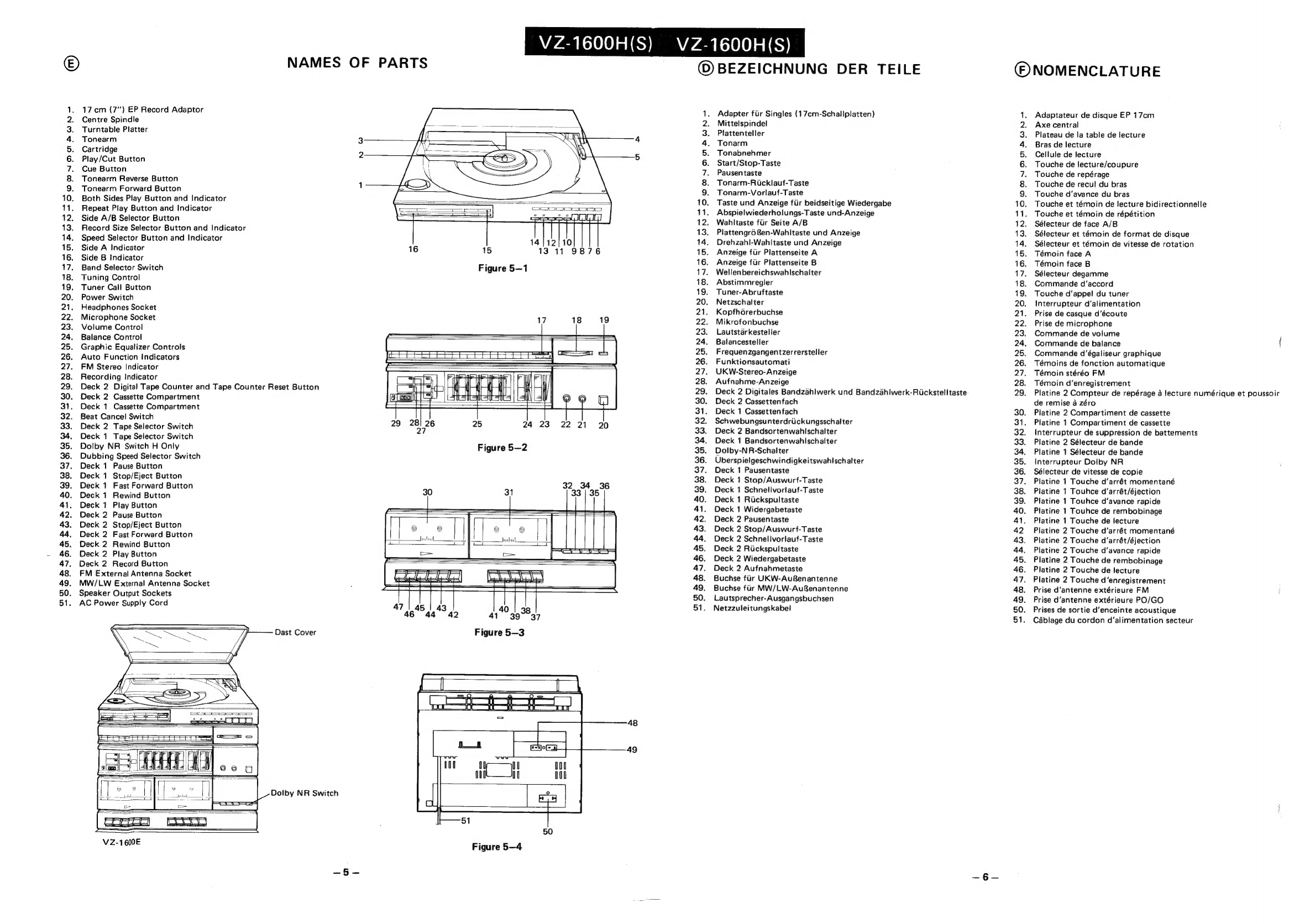
NAMES
OF
PARTS
17
cm
(7")
EP
Record
Adaptor
Centre
Spindle
Turntable
Platter
Tonearm
Cartridge
Play/Cut
Button
Cue
Button
Tonearm
Reverse
Button
Tonearm
Forward
Button
Both
Sides
Play
Button
and
Indicator
Repeat
Play
Button
and
Indicator
Side
A/B
Selector
Button
Record
Size
Selector
Button
and
Indicator
Speed
Selector
Button
and
Indicator
Side
A
Indicator
Side
B
Indicator
Band
Selector
Switch
Tuning
Control
Tuner
Call
Button
Power
Switch
Headphones
Socket
Microphone
Socket
Volume
Control
Balance
Control
Graphic
Equalizer
Controls
Auto
Function
Indicators
FM
Stereo
Indicator
Recording
Indicator
Deck
2
Digital
Tape
Counter
and
Tape
Counter
Reset
Button
Deck
2
Cassette
Compartment
Deck
1
Cassette
Compartment
Beat
Cancel
Switch
Deck
2
Tape
Selector
Switch
Deck
1
Tape
Selector
Switch
Dolby
NR
Switch
H
Only
Dubbing
Speed
Selector
Switch
Deck
1
Pause
Button
Deck
1
Stop/Eject
Button
Deck
1
Fast
Forward
Button
Deck
1
Rewind
Button
Deck
1
Play
Button
Deck
2
Pause
Button
Deck
2
Stop/Eject
Button
Deck
2
Fast
Forward
Button
Deck
2
Rewind
Button
Deck
2
Play
Button
Deck
2
Record
Button
FM
External
Antenna
Socket
MW/LW
External
Antenna
Socket
Speaker
Output
Sockets
AC
Power
Supply
Cord
~~
ee
Dast
Cover
Dolby
NR
Switch
VZ-1600E
VZ-1600H(S)
12/10
16
15
13°11
9876
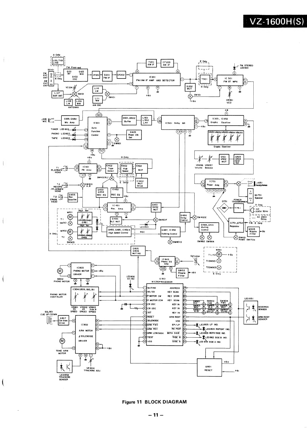
Figure
5—1
17
18
19
=
F
&
(J
[4
3
29
a6i26
25
24
23
22
21
20
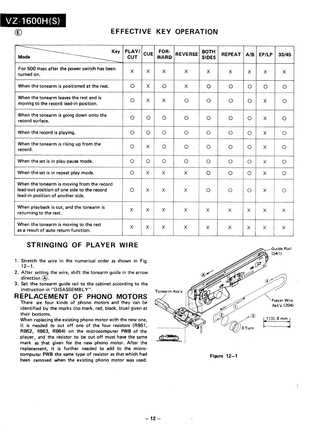
Figure
5—2
Figure
5—4
VZ-1600H(S)
(©)
BEZEICHNUNG
DER
TEILE
Adapter
fiir
Singles
{17cm-Schallplatten)
Mittelspindel
Plattenteller
Tonarm
Tonabnehmer
Start/Stop-Taste
Pausentaste
Tonarm-Rucklauf-Taste
Tonarm-Vorlauf-Taste
10.
Taste
und
Anzeige
fiir
beidseitige
Wiedergabe
11.
Abspielwiederholungs-Taste
und-Anzeige
12.
Wahltaste
fir
Seite
A/B
13.
PlattengroRen-Wahitaste
und
Anzeige
14.
Drehzahl-Wahltaste
und
Anzeige
15.
Anzeige
fiir
Plattenseite
A
16.
Anzeige
fiir
Plattenseite
B
17.
Welienbereichswahlschalter
18.
Abstimmregler
19.
Tuner-Abruftaste
20.
Netzschalter
SP
RSNADARWN>
21.
Kopfhoérerbuchse
22.
Mikrofonbuchse
23.
Lautstarkesteller
24.
Balancesteller
25.
Frequenzgangentzerrerstelier
26.
Funktionsautomati
27.
UKW-Stereo-Anzeige
28.
Aufnahme-Anzeige
29.
Deck
2
Digitales
Bandzahlwerk
und
Bandzahiwerk-Ruckstelltaste
30.
Deck
2
Cassettenfach
31.
Deck
1
Cassettenfach
32.
Schwebungsunterdriickungsschalter
33.
Deck
2
Bandsortenwahischaiter
34.
Deck
1
Bandsortenwahlschaiter
35.
Dolby-NR-Schalter
36.
Uberspielgeschwindigkeitswahlschalter
37.
Deck
1
Pausentaste
38.
Deck
1
Stop/Auswurf-Taste
39.
Deck
1
Schnellvorlauf-Taste
40.
Deck
1
Rickspultaste
41.
Deck
1
Widergabetaste
42.
Deck
2
Pausentaste
43.
Deck
2
Stop/Auswurf-Taste
44.
Deck
2
Schnellvoriauf-Taste
45.
Deck
2
Riickspultaste
46.
Deck
2
Wiedergabetaste
47.
Deck
2
Aufnahmetaste
48.
Buchse
fir
UKW-AuRenantenne
49.
Buchse
fur
MW/LW-AuRenantenne
50.
Lautsprecher-Ausgangsbuchsen
51.
Netzzuleitungskabel
(©)
NOMENCLATURE
{0:00
SGU
OL
BON
Adaptateur
de
disque
EP
17cm
Axe
central
Plateau
de
la
table
de
lecture
Bras
de
lecture
Cellule
de
lecture
Touche
de
lecture/coupure
Touche
de
repérage
Touche
de
recul
du
bras
Touche
d’avance
du
bras
Touche
et
témoin
de
lecture
bidirectionnelle
Touche
et
témoin
de
répétition
Sélecteur
de
face
A/B
Sélecteur
et
témoin
de
format
de
disque
Sélecteur
et
témoin
de
vitesse
de
rotation
Témoin
face
A
Témoin
face
B
Sélecteur
degamme
Commande
d'‘accord
Touche
d'appel
du
tuner
Interrupteur
d‘alimentation
Prise
de
casque
d’écoute
Prise
de
microphone
Commande
de
volume
Commande
de
balance
j
Commande
d’égaliseur
graphique
Témoins
de
fonction
automatique
Témoin
stéréo
FM
Témoin
d’enregistrement
Platine
2
Compteur
de
repérage
a
lecture
numérique
et
poussoir
de
remise
4
zéro
Platine
2
Compartiment
de
cassette
Platine
1
Compartiment
de
cassette
Interrupteur
de
suppression
de
battements
Platine
2
Sélecteur
de
bande
Platine
1
Sélecteur
de
bande
Interrupteur
Dolby
NR
Sélecteur
de
vitesse
de
copie
Platine
1
Touche
d’arrét
momentané
Platine
1
Touhce
d’arrét/éjection
Platine
1
Touhce
d’avance
rapide
Platine
1
Touhce
de
rembobinage
Platine
1
Touche
de
lecture
Platine
2
Touche
d’arrét
momentané
Platine
2
Touche
d’arrét/éjection
Platine
2
Touche
d‘avance
rapide
Platine
2
Touche
de
rembobinage
Platine
2
Touche
de
lecture
Platine
2
Touche
d’enregistrement
Prise
d’'antenne
extérieure
FM
Prise
d’'antenne
extérieure
PO/GO
Prises
de
sortie
d’enceinte
acoustique
Cablage
du
cordon
d’alimentation
secteur