Shimadzu MOC-120H User manual

321-78153
Aug, 2014
ELECTRONIC MOISTURE METER
MOC-120H
SERVICE MANUAL
SHIMADZU CORPORATION
Kyoto,JAPAN

- 0 -
Contents
1. Table of Malfunction Causes 1
2. Troubleshooting 5
3. Service Mode of MOC-120H 13
4. Replacing the Heater Assembly 14
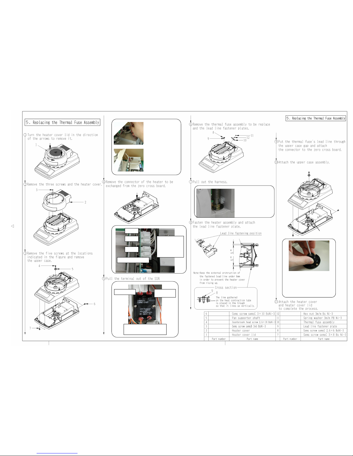
5. Replacing the Thermal Fuse Assembly 15
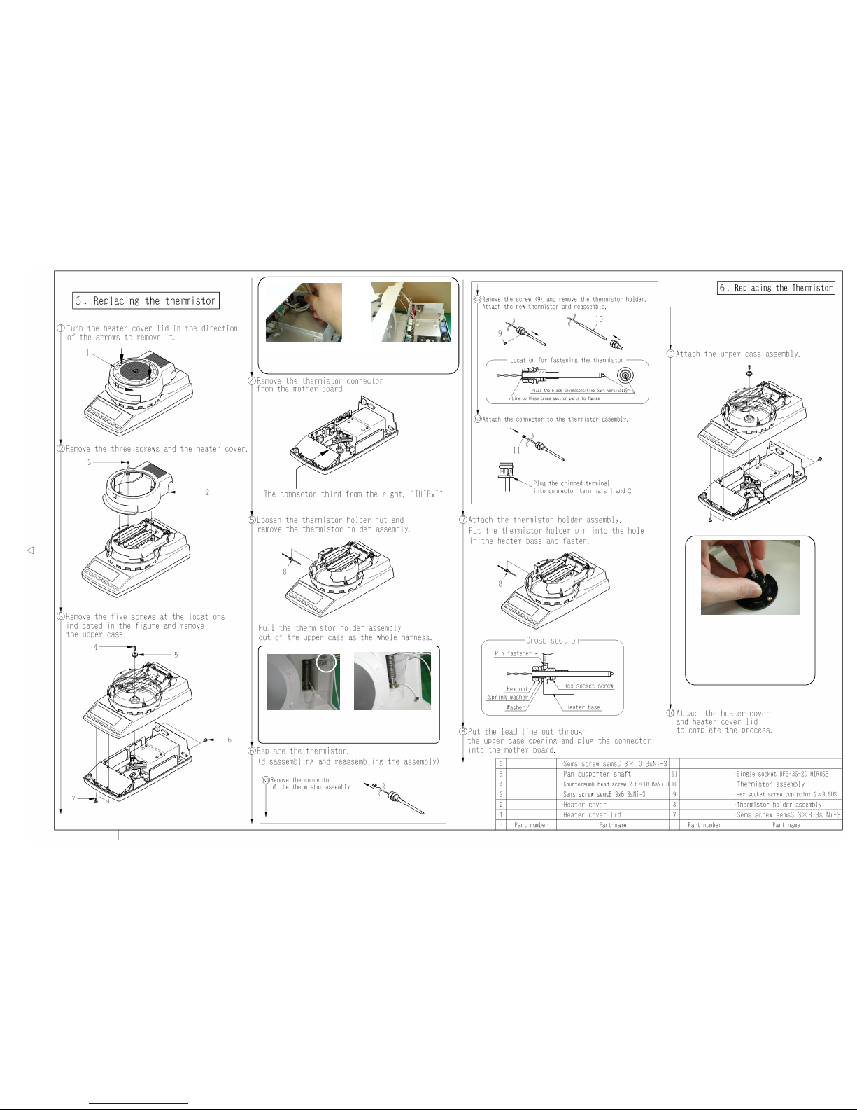
6. Replacing the Thermistor 16
7. Replacing the Motherboard 17
8. Replacing the Motor and PI Board Assembly 18
9. Replacing the Balance Assembly 19
10. Readjusting the Heater Cover 21
11. Adjusting the Linearity of the Electric Balance Unit 22
12. Parts list 23

- 1 - - 1 -
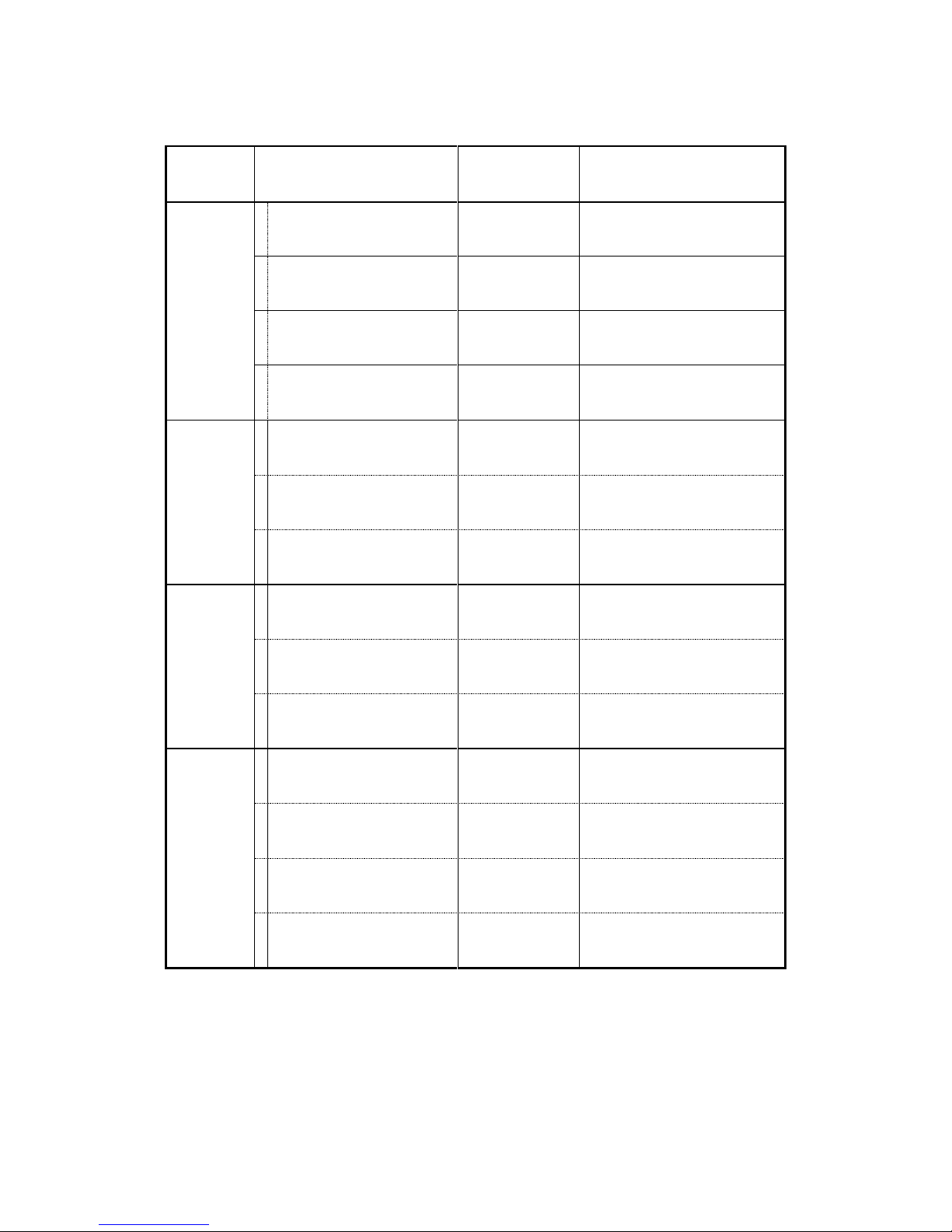
1.Table of Malfunction Causes
Malfunction
Causes
Solutions
Inspection Method After
Repairs
Power will not
turn on
(LCD does
not light)
1
Power cord not
connected
Connect power
cord
Turn power on again
2
Fuse disconnected
Replace fuse
3
Power voltage
malfunction
Use with correct
power
4
Bad inlet connector
contact
Reattach
connector
5
SW power malfunction
Replace SW
power
6
Motherboard
malfunction
Replace
motherboard
Complete acceptance
inspection
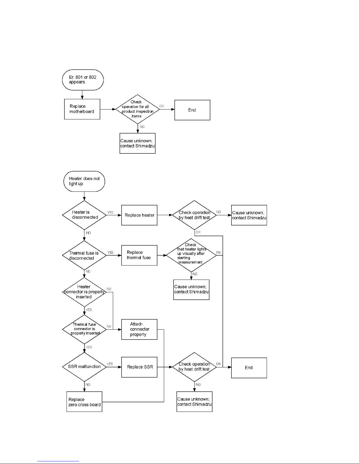
Heater does
not light up
1
Heater disconnected
Replace heater
Heat drift test
2
Thermal fuse
disconnected
Replace thermal
fuse
Check heater light up visually
3
Bad heater connection
contact
Reattach
connector
Heat drift test
4
SSR malfunction
Replace SSR
Heat drift test
5
Zero cross board
malfunction
Replace zero
cross board
Heat drift test
Mass
measurement
is unstable
(values
constantly
changing)
1
Lift unit touching
another part
Readjust lift unit
Heat drift test
2
Balance malfunction
Replace balance
Complete acceptance
inspection
“CHEO” or
“-oL” display
does not
disappear
1
Motherboard
malfunction
Replace
motherboard
Complete acceptance
inspection
2
Balance malfunction
Replace balance
Complete acceptance
inspection

- 2 - - 2 -
Malfunction
Causes
Solutions
Inspection Method After
Repairs
Er. 102, 103,
104
Er. 201, 202
1
Incorrect usage
Use properly
Check proper usage
2
Malfunction due to ROM
ver. 7212 or earlier
Replace
motherboard
Complete acceptance
inspection
3
Improper lift unit adjustment
Readjust lift unit
Heat drift test
Er. 301, 302
1
Bad thermistor connection
contact
Reattach
connector
Check at room temperature,
heat drift test
2
Thermistor malfunction
Replace
thermistor
Check at room temperature,
heat drift test
3
Motherboard malfunction
Replace
motherboard
Complete acceptance
inspection
Er. 303
1
Improper thermistor
attachment position
Reattach
thermistor
Check at room temperature,
heat drift test
2
Thermistor malfunction
Replace
thermistor
Check at room temperature,
heat drift test
3
Motherboard malfunction
Replace
motherboard
Complete acceptance
inspection
Er. 304
1
Malfunction due to ROM
ver. 7212 or earlier
Replace
motherboard
Complete acceptance
inspection
2
Bad thermistor connection
contact
Reattach
connector
Check at room temperature,
heat drift test
3
Thermistor malfunction
Replace
thermistor
Check at room temperature,
heat drift test
4
Motherboard malfunction
Replace
motherboard
Complete acceptance
inspection
Er. 305
1
Heater disconnected
Replace heater
Heat drift test
2
SSR malfunction
Replace SSR
Heat drift test
3
Motherboard malfunction
(runaway)
Replace
motherboard
Complete acceptance
inspection
Er. 306
1
Improper usage
Use properly
Check proper usage
2
Heater SW malfunction
Replace heater
SW
Check operation during
measurement
- 3 - - 3 -
Malfunction
Causes
Solutions
Inspection Method After
Repairs
Er. 401
1
Bad balance connector
contact
Reattach
connector
Complete acceptance
inspection
2
Balance board malfunction
Replace balance
board
Complete acceptance
inspection
3
Motherboard malfunction
Replace
motherboard
Complete acceptance
inspection
4
Balance malfunction
Replace balance
Complete acceptance
inspection
Er. 501, 502
1
Incorrect usage (CAL
method)
Use properly
Check proper usage
2
Bad balance connector
contact
Reattach
connector
Complete acceptance
inspection
3
Balance malfunction
Replace balance
Complete acceptance
inspection
Er. 601, 602
1
Bad motor connector
contact
Reattach
connector
Check operation during
measurement
2
Motor malfunction
Replace motor
Check operation during
measurement
3
Motherboard malfunction
Replace
motherboard
Complete acceptance
inspection
Er. 603
1
Bad motor connector
contact
Reattach
connector
Check operation during
measurement
2
Improper PI board
attachment
Reattach PI
board
Check operation during
measurement
3
PI board malfunction
Replace PI board
Check operation during
measurement
4
Motherboard malfunction
Replace
motherboard
Complete acceptance
inspection

- 4 - - 4 -
Malfunction
Causes
Solutions
Inspection Method After
Repairs
Er. 701, 702
1
Incorrect usage (power
selection SW)
Use properly
Check proper usage
2
Power voltage problem
Use correct
power
Turn power on again
3
SW power malfunction
Replace SW
power
Turn power on again
Er. 801, 802
1
Motherboard malfunction
Replace
motherboard
Complete acceptance
inspection
- 5 - - 5 -
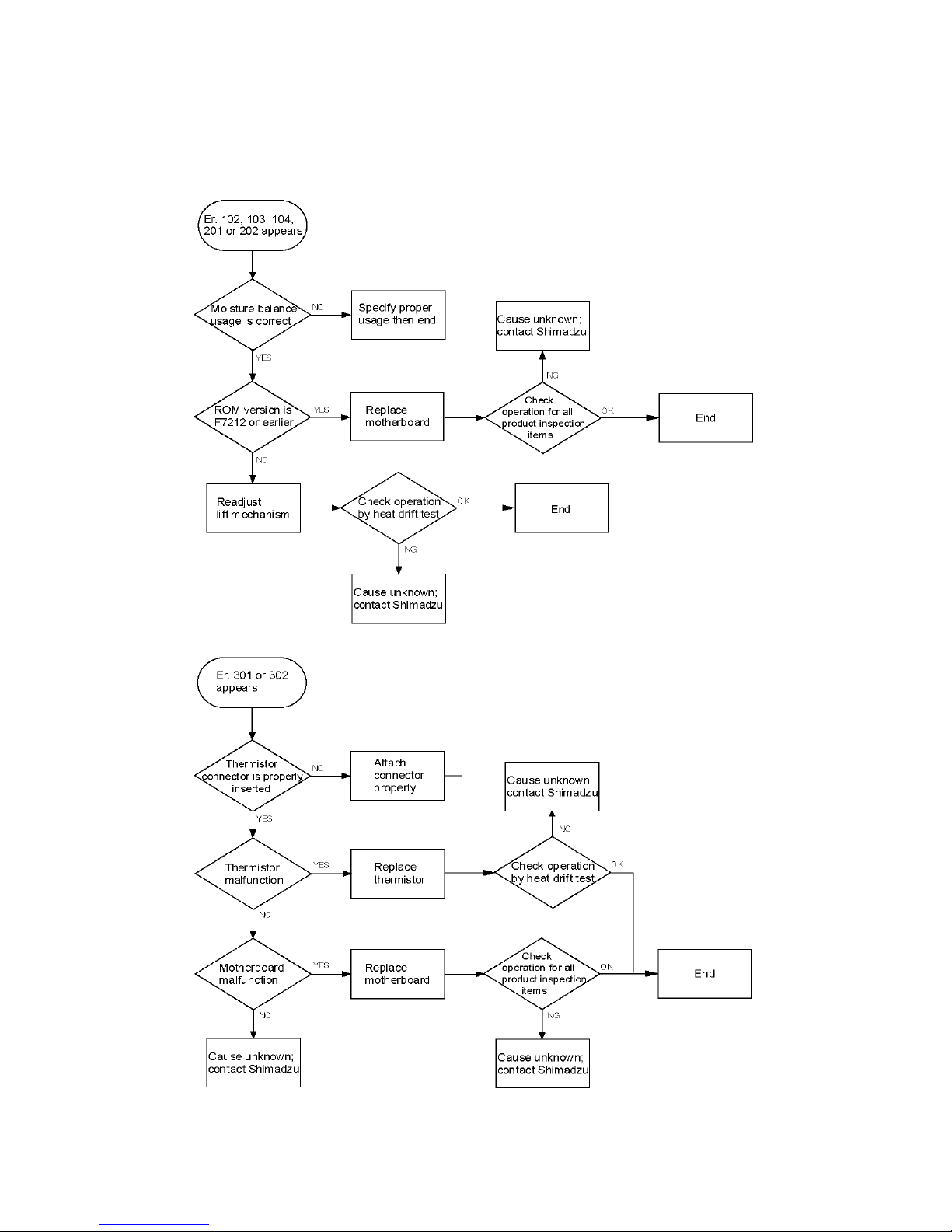
2.Trouble shooting
2-1【Er. 102, 103, 104, 201, 202】
2-2【Er. 301, 302】

- 6 - - 6 -
2-3【Er. 303】
2-4【Er. 304】

- 7 - - 7 -
2-5【Er. 305】
2-6【Er. 306】
- 8 - - 8 -
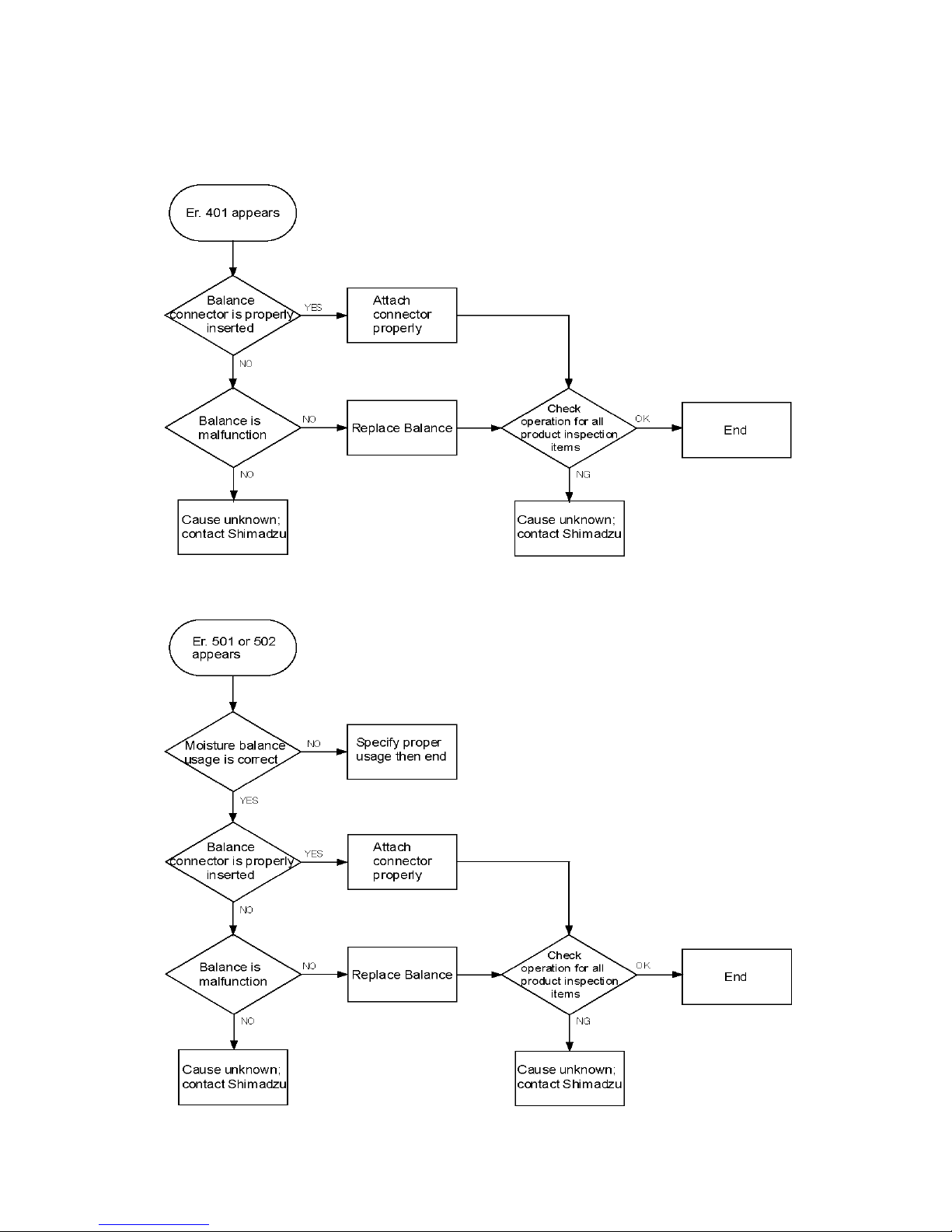
2-7【Er. 401】
2-8【Er. 501,502】
- 9 - - 9 -
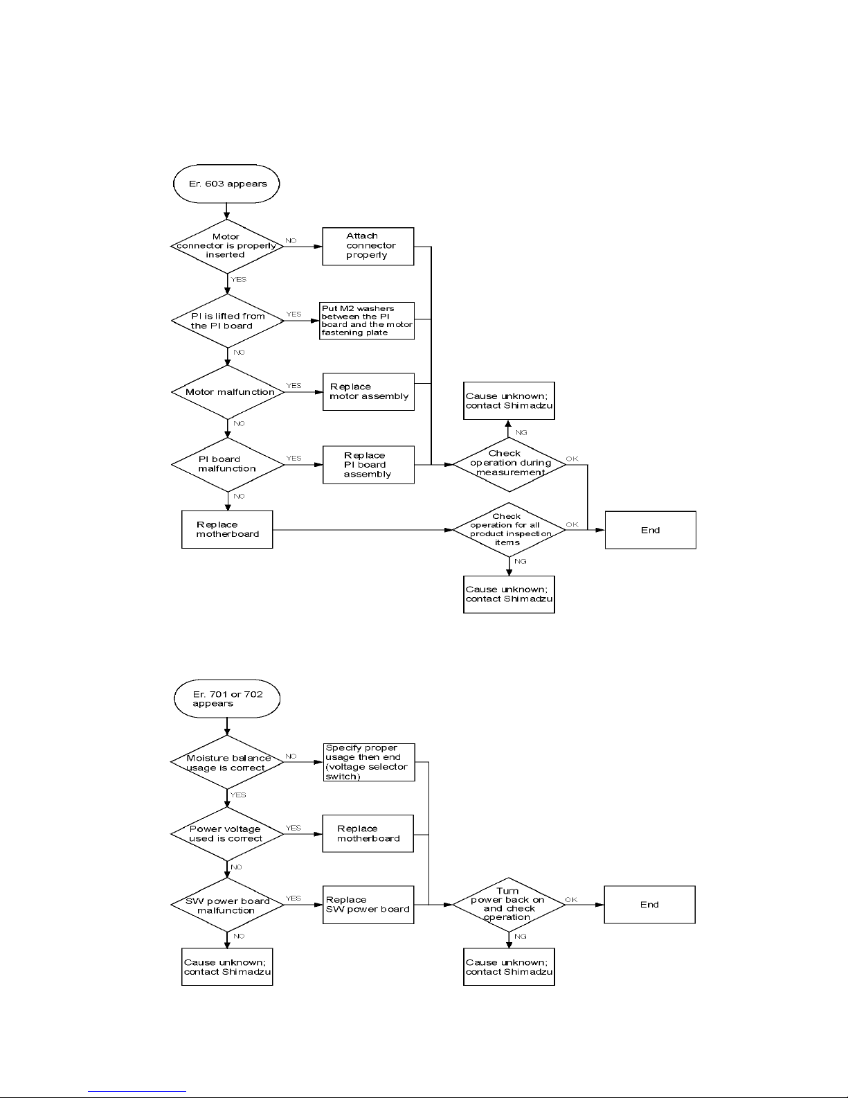
2-9【Er. 603】
2-10【Er. 701,702】
- 10 - - 10 -
2-11【Er. 801 or 802】
2-12【Heater does not light up】

- 11 - - 11 -
2-13【Mass Measurement is Unstable】
2-14【After Turning Power On, “CHEO”, “-oL” or Other Display Does Not Turn Off】

- 12 - - 12 -
2-15【Power will not turn on (LCD does not light)】
- 13 - - 13 -
3.Service Mode of MOC-120H
Key 1
Key 2
Action
START+TARE+ENTER
Power SW
EEPROM data set to factory setting
CONDITION+MENU
Balance TAD, WAD output in measuring
START or TARE
All segment indicate
ENTER
START
(Hold 5sec)
EEPROM data output
UP
Range of zero trucking set
DOWN
LCD test mode
ENTER
TARE
(Hold 5sec)
Software Ver. indicate
SELECT
Key inspection mode
UP
Power High time indicate
DOWN
S/N input
UP
MENU
(Hold 5sec)
Maker name input
DOWN
Model name input

- 14 -
Zero cross board
Heater
Heater
Power
SSR/Thermal Fuse
Of the connectors on the upper
part of the zero cross board,
the two on the back portion of
the device are for the heater.
Remove the lead line from
the cord clip at the side of
the connector and the cord
clip on the upper case.
Pull the connector out
through the location shown
in the picture. When doing
this, kinks in the lead line will
make it difficult to pull out so
pull any kinks straight before
pulling out.
To prevent the pan supporter arm (the female
thread side) from turning when attaching the
pan supporter shaft (top), tighten the screws
while holding the pansupporter shaft as shown
in the picture.
If the pan supporter arm turns and touches
other parts, accurate measurements are not
possible.
Also, please note that tightening it too much
can cause breaking or cracks.
Pan support arm
Open the upper case
while taking care with the
harness lead.
Open while pushing it over
to the left and stand it up
as is without completely
disassembling.
- 15 - - 15 -
Open the upper case
while taking care with
the harness lead.
Open while pushing it
over to the left and
stand it up as is without
completely
disassembling
Zero cross board
Heater
Heater
Power
SSR/Thermal Fuse
Of the connectors on
the upper part of the
zero cross board, the
two on the most front
portion of the device
are for the thermal
fuse.
To prevent the pan supporter arm (the
female thread side) from turning when
attaching the pan supporter shaft (top),
tighten the screws while holding the pan
supporter shaft as shown in the picture.
If the pan supporter arm turns and
touches other parts, accurate
measurements are not possible.
Also, please note that tightening it too
much can cause breaking or cracks.
Pan support arm
Thermal fuse
via zero cross
Thermal fuse
Of the four SSR connectors, two at
the back of the device are
connected to the thermal fuse
Remove the lead line from the
cord clip at the side of the
connector and the cord clip on
the upper case.
Pull the connector out through
the location shown in the
picture. When doing this, kinks
in the lead line will make it
difficult to pull out so pull any
kinks straight before pulling
out.
- 16 - - 16 -
Open the upper case
while taking care with the
harness lead.
Open while pushing it over
to the left and stand it up
as is without completely
disassembling
Remove the lead line from
the bottom case cord clip
and the cord clip shown
circled in the picture.
Pull the connector trough
and out as shown in the
picture.
To prevent the pan supporter arm (the
female thread side) from turning when
attaching the pan supporter shaft (top),
tighten the screws while holding the pan
supporter shaft as shown in the picture.
If the pan supporter arm turns and
touches other parts, accurate
measurements are not possible.
Also, please note that tightening it too
much can cause breaking or cracks
Pan support arm

- 17 - - 17 -
Open the upper case
while taking care with
the harness lead
Open while pushing it
over to the left and
stand it up as is without
completely
disassembling.
To prevent the pan supporter arm
(the female thread side) from
turning when attaching the pan
supporter shaft (top), tighten the
screws while holding the pan
supporter shaft as shown in the
picture.
If the pan supporter arm turns and
touches other parts, accurate
measurements are not possible.
Also, please note that tightening it
too much can cause breaking or
cracks.
Peel off the LCD protection sticker
Check whether there is
a jumper line to the
SW0
FD720 : No line
MOC120H : Has line
Set the battery
If the buzzer seal is
still on, remove it.
Front
Bac
k
12V
2P
MOTOR
6P
SSR
3P
THIRMO
6P
PN-847
4P
232C
6P
BALANCE
6P
THIRMI
3P
●Checking the board
●Connector Attachment Notes
The name printed on the motherboard and number of pins for
each connector.
Connector types "MOTOR", "THIRMO", "BALANCE", and
"232C" all have 6 pins each while "SSR" and "THIRMI" have
three pins each.
Pay close attention to "BALANCE" and "232C" as their
plugs are right next to each other.
●Entering the Serial Number (Hidden Mode)
In mass display mode,
▼+ Tare/Start (hold down for 5 seconds)
"Sn" will appear in the center of the LCD and a serial number will appear as
four digits at a time.
Change the letters and numerals by pressing ▲and ▼and confirm each
digit by pressing ENTER.
●Entering the Date and Time
In mass display mode,
Menu
Press Select 3 times.
DATE will appear on the lower part of the LCD.
Press ENTER
The current date display format will appear (YMD, etc.).
To change the format, press Select and ENTER after setting.
Set "YEAR" by pressing ▲and ▼and press ENTER after setting.
Set "MONTH, DAY" and "HOUR, MINUTE" the same way.
After setting "MINUTE" and pressing ENTER, the clock will start at zero
seconds.

- 18 - - 18 -
Open the upper case
while taking care with the
harness lead.
Open while pushing it over to the
left and stand it up as is without
completely disassembling.
To prevent the pan supporter arm (the
female thread side) from turning when
attaching the pan supporter shaft (top),
tighten the screws while holding the pan
supporter shaft as shown in the picture.
If the pan supporter arm turns and
touches other parts, accurate
measurements are not possible.
Also, please note that tightening it too
much can cause breaking or cracks.
Pan support arm
Other manuals for MOC-120H
1
Table of contents
Other Shimadzu Measuring Instrument manuals

Shimadzu
Shimadzu TOC-V CPH User manual

Shimadzu
Shimadzu MOC63 User manual

Shimadzu
Shimadzu UV-1800 User manual

Shimadzu
Shimadzu MOC-120H User manual

Shimadzu
Shimadzu AGS-X Series User manual

Shimadzu
Shimadzu AA-7000 Series User manual

Shimadzu
Shimadzu PDA-7000 User manual

Shimadzu
Shimadzu UV-2401 PC User manual

Shimadzu
Shimadzu MOC63u User manual

Shimadzu
Shimadzu GCMS-QP2010 Series User manual


