Shimadzu UV-2401 PC User manual
20694376C
INSTRUCTION MANUAL
User’s System Guide
SPECTROPHOTOMETER
UV-2401 PC (P/N 206982201/206-55670)
UV-2501 PC (P/N 206-82251/206-55674)
I
Read the instruction manual thoroughly before you use the product. Keep I
I
this instruction manual with caresothat you canuse it any time you need it. I
I I
SWIMADZU CORPORATION
ANALYTICAL INSTRUMENTS DlVlSlON
KYOTO, JAPAN

Copyright 0 Shimadzu Corporation 1997. All rights are reserved, including those to
reproduce this publication or parts there of in any form without permission in writing
from Shimadzu Corporation.
Information in this publication is subject to changewithout notice and doesnot represent
acommitment on thepart of the vendor.
Any errors or omissions which may have occurred in this publication despite the utmost
caretaken in its production will be corrected assoon aspossible, but not necessarily im-
mediately upon detection.
Note that Shimadzu does not have any obligation concerning the effects resulting from
the application of the contensof this manual.
The lock band of D2 lamp in the light source compartment isn’t used
in this instrument. So it isn’t necessary to release the spring of the
lock band in light source replacement procedure .


UV-2401/2501 PC is aW-Visible Spectrophotometer.
Tooperatetheunit safety, strictly observethe following precautions.
It is dangerousnot to comply with the following points.
1. Do not usetheunit for anypurpose other thanthe above-mentioned types of analysis.
2. Follow the proceduresdescribed in the user’s manual.
3. Observeall warnings andcautions.
4. Do not disassembleor modify the unit without the expressapproval of authoried Shimadzu
Representative.Failing to do so may lead dangeroussituation or damageof the unit.
5. Do not useatthe method not to indicate in the instruction manual. Failing to do somay lead
dangeroussituation or damage of the unit.
6. For internal repair of the product, contact your Shimadzu Representative.
MEANING OF CAUTION SIGNS
1-1 indicates a potentially hazardous situation which, if not
avoided, could result in death, serious injury or moderate
injury.
m] indicates a potentially hazardous situation which, if not
avoided, may result in minor injury, or may result in machine
damage.
)I is used to emphasize essential information.
MEANING OF SAFETY SYMBOLS
A
!I
Voltage is dangerously high.
HOT SURFACE
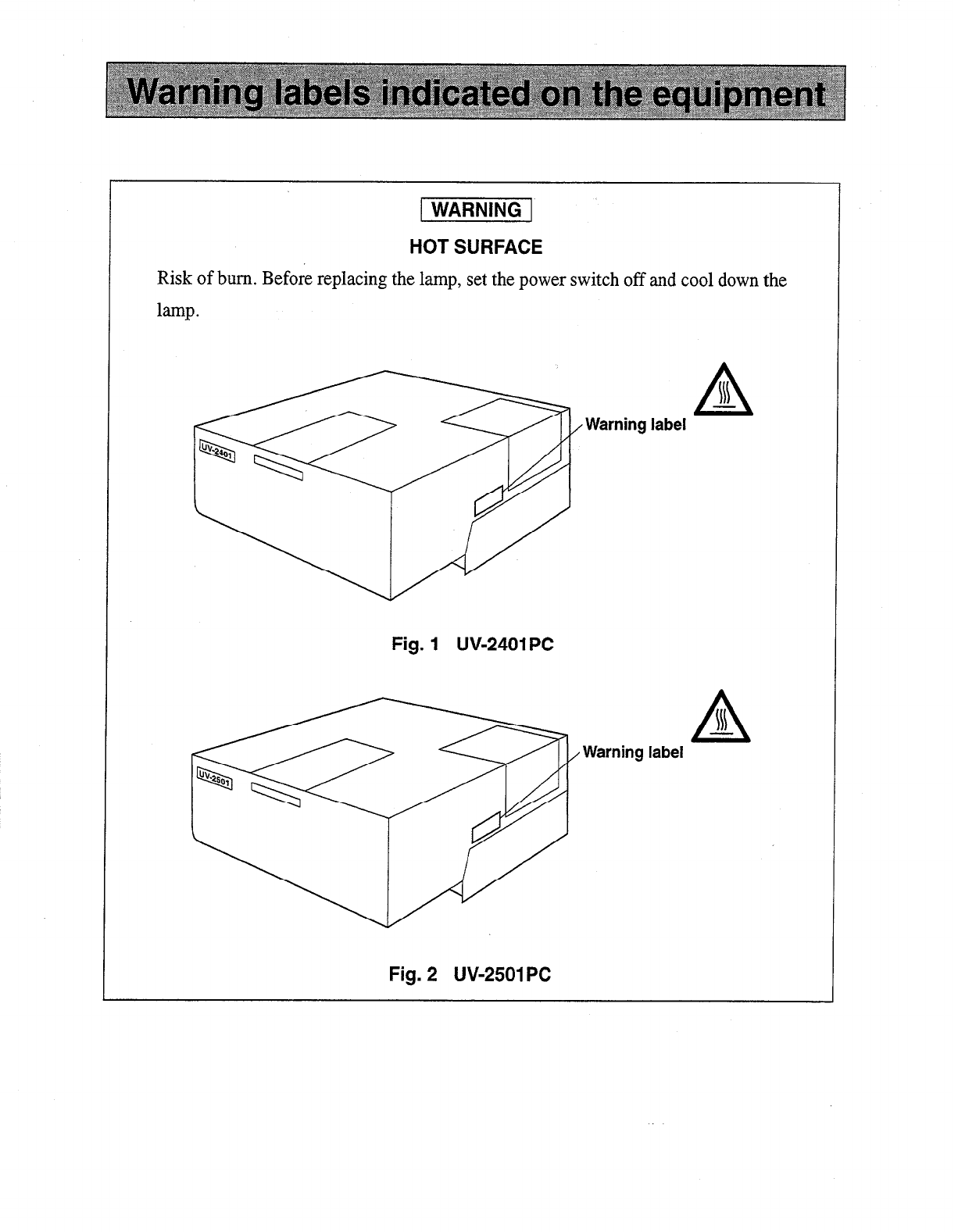
HOT SURFACE
Risk of burn. Before replacing the lamp, setthe power switch off andcool down the
lamp.
A
N
-
Warning label
Fig. 1 UV-2401PC
Warning label
Fig. 2 UW25OlPC

RISK OF ELECTRIC SHOCK
Before replacing the fusesor changing the power sourcevoltage, readInstruction
Manual.
Warning label
A
Fig. 3 UW2401PC
Warning label
Fig. 4 UV52501PC
I Symbol
I
F
0
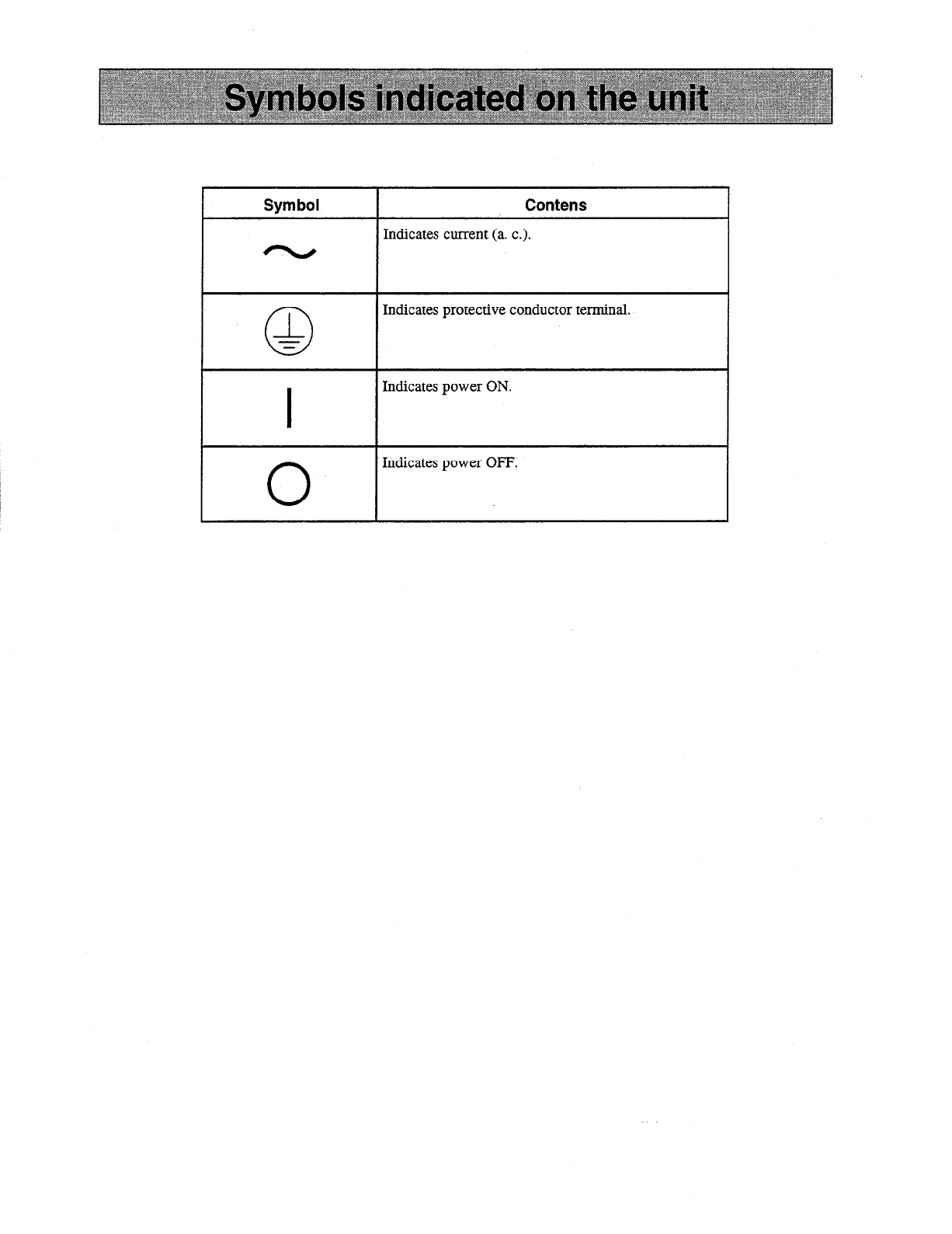
Contens
Indicates current (a. c.).
Indicates protective conductor terminal.
Indicates power ON.
Indicates power OFF.

For Europe :
The product complies with the requiremnts of the EMC Directive 89/336/EEC, and Low
Voltage Directive 73/23/EEC.
Product name : UV-Visible Spectrophotometer
Model name : UV-2401 PC
UV-2501PC
Manufacturer : SHIMADZU CORPORATION
ANALYTICAL INSTRUMENTS DIVISION
Address : 1,NISHINOKYO-KUWABARACHO,
NAKAGYO-KU, KYOTO, 604-8511,JAPAN
Authorized Representativein EU : SHIMADZU Deutschland GmbH
Address : Albert-Hahn-Strasse 6-10, D-47269
Dusisburg, F,R, Germany


1.
Inspection ................................................................................................................. l- 1
1.1 Inspection ................................................................................................................ l- 2
2. Installation .................................................................................................................. 2 - 1
2.1 Hardware installation .............................................................................................. 2- 2
2.1.1 Site requirements ........................................................................................... 2- 2
2.1.2 Environmental requirements .......................................................................... 2- 2
2.1.3 Instrument voltage setting................................................................................ 2 - 3
2.1.4 Personalcomputer hardware andsoftware requirements .............................. 2- 3
2.15 Cable connections .......................................................................................... 2- 4
2.2 Software installation ................................................................................................ 2- 6
2.3 Communications andprinter setup .......................................................................... 2 - 7
2.4 System Initialization ................................................................................................ 2- 8
2.5 Electra Magnetic Compatibility .............................................................................. 2- 10
3. Construction.. 3 -............................................................................................................. 1
3.1 W-2401/250 1PCPhotometer Unit 3 -
......................................................................... 2
3.2 Sample compartment of UV-2401/25OlPC photometer unit .................................. 3- 4
3.3 Photometric System 3 -................................................................................................. 5
3.3.1 Optical System (UV-2401PC) ........................................................................ 3- 5
3.3.2 Optical System (UV-25OlPC) ........................................................................ 3- 7
3.3.3 Cell holder/Light Beam Relative Position -..................................................... 3 9
3.3.4 Electrical system ............................................................................................ 3- 9
4. Maintenance and Checking .................................................................................... 4- 1
4.1 Periodic Maintenance ................................................................................................ 4- 2
4.2 Troubleshooting -......................................................................................................... 4 4
4.2.1 Photometer Initialization failures ..................................................................... 4- 4
4.2.2 Scanning Problems .......................................................................................... 4- 5
4.3 Replacement of the light source .............................................................................. 4- 7
4.3.1 Light sourcespecifications ............................................................................ 4- 7
4.3.2 Light sourcereplacementprocedure .............................................................. 4- 7
4.4 Replacement of the fuses ......................................................................................... 4 - 10
4.5 Cleaning the Unit .................................................................................................... 4- 12
4.6 Consumable/Spare Parts list for maintenance ......................................................... 4- 13
4.7 Precaution During Transportation of the Unit ......................................................... 4- 14
5. Specifications ............................................................................................................ 5 . 1
5.1 UV-2401/25OlPC .................................................................................................... 5 . 2
6. Optional Accessories ............................................................................................... 6 - 1
6.1 Optional Cells .......................................................................................................... 6 - 2
7. Index ~............................................................................................................................ 7 - 1
..
Chapter 1 Inspection
jl
1.1 Inspection ....................................................................................... l-l
I 1
E
0
.-
5
2i.
E
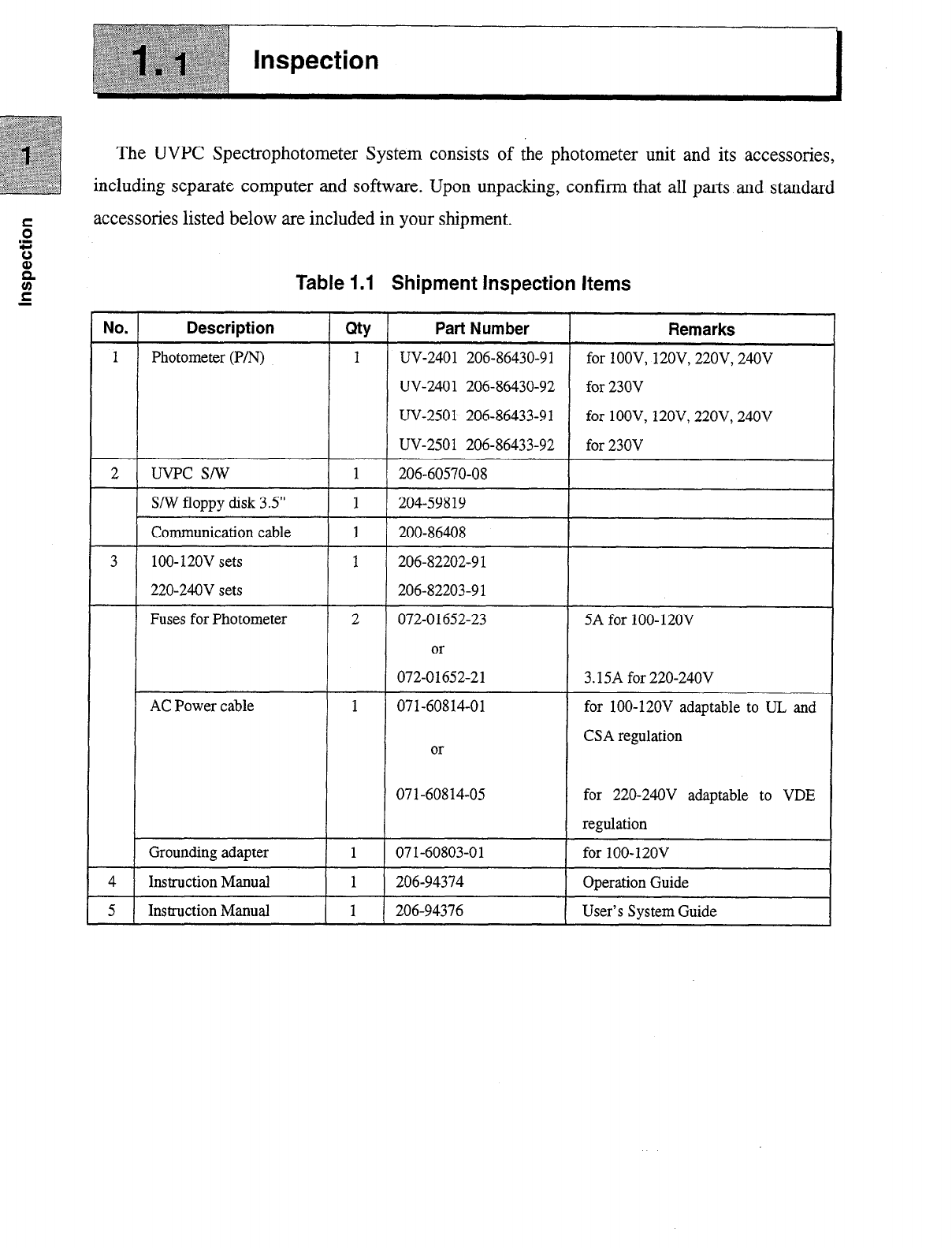
The UVPC Spectrophotometer System consists of the photometer unit and its accessories,
including separatecomputer and software. Upon unpacking, confirm that all parts and standard
accessorieslisted below areincluded in your shipment.
z
‘c;
0
E Table 1.1 Shipment Inspection Items
2
UV-2401 206-86430-92
UV-2501 206-86433-91 for lOOV, 12OV, 22OV, 240V
AC Power cable for lOO-120V adaptable to UL
for 220-24OV adaptable to VDE

Chapter 2 Installation
2.1 Hardware installation ................................................................ 2 - 2
2.1.1 Site requirements ............................................................. 2- 2
2.1.2 Environmental requirements ............................................ 2- 2
2.1.3 Instrument voltage setting ................................................. 2- 3
2.1.4 Personalcomputerhardwareandsoftware requirements ... 2 - 3
2.1.5 Cable connections ............................................................ 2- 4
2.2 Software installation ................................................................. 2- 6
2.3 Communications andprinter setup ........................................... 2- 7
2.4 System Initialization ................................................................. 2- 8
2.5 Electra Magnetic Compatibility ................................................ 2- 10
Hardware
installation
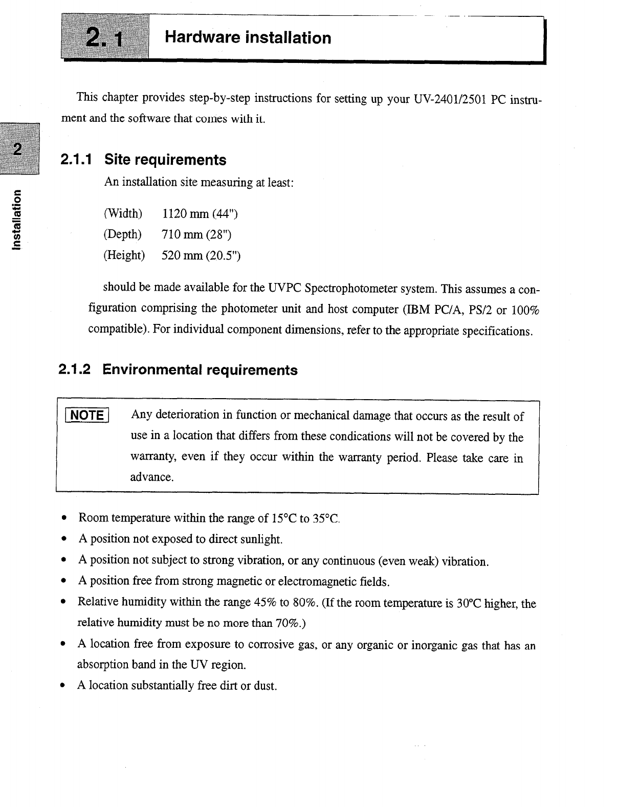
This chapter provides step-by-step instructions for setting up your UV-2401/2501 PC instru-
ment andthe software that comes with it.
2.1 .I Site requirements
An installation site measuring atleast:
(Width) 1120mm (44”)
(Depth) 710 mm (28”)
(Height) 520 mm (20.5”)
should bemade available for the UVPC Spectrophotometer system. This assumesacon-
figuration comprising the photometer unit and host computer (IBM PC/A, PS/2 or 100%
compatible). For individual component dimensions, referto the appropriatespecifications.
2.1.2 Environmental requirements
p6TE-j
Any deterioration in function or mechanical damagethat occurs astheresult of
usein a location that differs from thesecondications will not be covered by the
warranty, even if they occur within the warranty period. Please take care in
advance.
l
Room temperature within the rangeof 15°Cto 35°C.
l
A position not exposed to direct sunlight.
l
A position not subject to strong vibration, or any continuous (evenweak) vibration.
l
A position free from strong magnetic or electromagnetic fields.
l
Relative humidity within the range45% to 80%. (If the room temperature is 30°Chigher, the
relative humidity must be no more than 70%.)
l
A location free from exposure to corrosive gas, or any organic or inorganic gasthat has an
absorption bandin the UV region.
l
A location substantially free dirt or dust.

2.1 Hardware installation
2.1.3 Instrument Voltage setting
r
[ml
Check the following points before connecting the power.
0
Power supply voltage andpower supply capacity
100/120/220/230/240’ AC+lO% 19OVA 50/60Hz
If the power supply voltage is unstable or power supply capacity insufficient,
the unit does not function properly. Also, it is necessaryto check the power
supply of entire unit before providing thepower supply.
Further, if fluctuation of the power supply voltage is more than 1 lo%, usethe
constantvoltage unit.
Power sourcevoltage varies according to the geographic region. A voltage selector is provid-
edat the left side of the instrument (in the fuse holder compartment) to allow setting the voltage
(100, 120,220,230 or 240V) appropriate to the region.
To changethe voltage, usea screwdriver to pry openthe fuseholder cover. Remove the drum-
shapedvoltage selector.Re-insert the voltage selector,making surethat the appropriate voltage is
displayed. Then re-mount the fuse holder cover.
[m]
RISK OF ELECTRIC SHOCK
Before changing a fuse or the inlet voltage, turn off the power switch and
disconnect the power cable.
1-1 Use a SA fuse for lOO-120V setting, and a3.15A fuse for 220-240V power
voltage settings.
L
2.1.4 Personal computer hardware and software requirements
In addition to the UVPC photometer unit, UVPC software, and standardaccessories,the
following hardware and software areeither required (andtherefore provided with the com-
plete system), recommended
or
useful.
Minimum hardware requirements:
l
IBM PC/AT (or 100% compatible) or IBM PS/2,Model 50andhigher
l
16M Random Access Memory (RAM)
2.1 Hardware installation
l
1 floppy disk drive (3.5”)
l
1 hard disk drive (200MB)
l
Windows-compatible graphics adapter/ monitor with 640 x 480 resolution
l
IBM compatible synchronous serial port
Minimum software requirements:
l
MS or PC Disk Operating System (DOS), Version 5.0
l
Windows3.1 or Windows95
Recommended optional accessories
l
Mouse-type pointing device
l
IBM compatible parallel port and Windows compatible graphics printer
2.1.5 Cable connections
The connections described in this section assume installation of the components sup-
plied as standard with this system. For installation of components not standard with this
system, refer to the appropriate instruction manuals.
Install the photometer unit and computer components and cables and set the switches as
indicated in the illustration below. (refer to Section 3.1 “Fig. 3.1”).
Confirm that Power switch is set to OFF. Then connect the attached AC power cord to
the Power inlet of the UV-2401/2501 PC and the AC power source.
Be sure to use a grounded power source receptacle if possible.
If the employed power source receptacle is not equipped with a ground terminal, ground
the instrument using the ground terminal.
-1 When performing grounding
l
Be sure to unplug the power cord before connecting or disconnecting a
gronud wire.
l
If peripheral devices are being used, be sure to disconnect all power cords
before connecting the ground.
l
Do not connect the ground wire to a gas pipe under any circumstances.
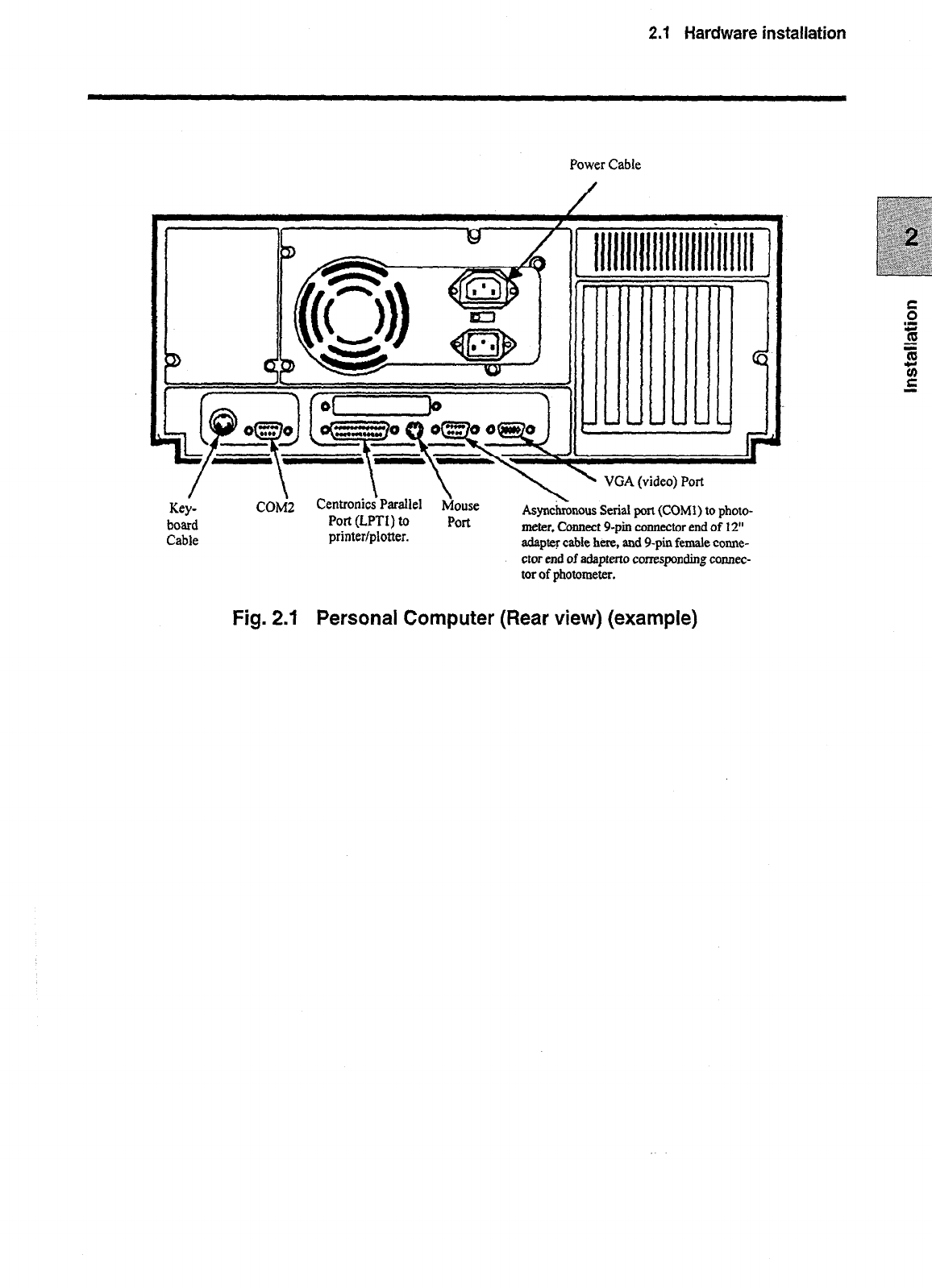
2.1 Hardware installation
Power Cable
\ \ VGA (video) Port
board
Cable
COM>
Fig. 2.1 Personal Computer (Rear view) (example)
Centronics’Parallel Gouse
Port(LPTI) to Port Asyncknous Serialport(COMl) tophoto-
printer/plotter. meter,Connectg-pinconnectorendof 12”
adaptercablehere,andg-pinfemalecomte-
ctorendof adaptertocorrespondingconnec-
torof photometer.

Software installation
Before installing the UVPC software, it is necessary to first install Microsoft Windows
Version 3.1 or Windows95. Pleaserefer to theappropriate Microsoft Windows documentation for
the installation procedure. The installation procedure for the UVPC software is performed as
described below.
pmq
Before installing, please check that write-protect (installer floppy disk) is OPF.
If it is ON, please start to install after you make it OFF. (Error occurs if you
startto install on ON.)
Procedure
1.
Insert the UVPC floppy disk into theA: drive andstart“Install.exe”.
2. At the prompt, type in the drive anddirectory where UVPC software is to be installed. The
default directory canbeacceptedby simply pressing ENTER.
3. At the prompt, enteryour company’s name or the nameof thelicensee.
4. While the Install program is copying information from the disk, take the time to fill out the
product registration card so that you canbe notified when future upgradesand optional soft-
ware areavailable.
5. When the installation is complete, you will be given the opportunity to view the
READMBTXT file. It is highly recommended that you readthis file, since it contains impor-
tant information that did not get into this manual.
6. This completes the software installation procedure. You will find that the installation pro-
gram has createda “Shimadzu” group in Program Manager andhasaddedthe UVPC icon to
it. Double click on the UVPC icon andproceed to the next section, “Communications and
printer setup.”
p6TE-l
If the software was previously installed on the system,the previous installation
will be over written and a second icon will appear in the shimadzu group.
Chooseone of the icons andselectdeleteto remove it from thegroup.
This manual suits for next models
5
Table of contents
Other Shimadzu Measuring Instrument manuals

Shimadzu
Shimadzu UV-1700 series User manual

Shimadzu
Shimadzu PDA-7000 User manual

Shimadzu
Shimadzu MOC-120H User manual

Shimadzu
Shimadzu AGS-X Series User manual

Shimadzu
Shimadzu UV-1800 User manual

Shimadzu
Shimadzu MOC-120H User manual

Shimadzu
Shimadzu AA-7000 Series User manual

Shimadzu
Shimadzu IRAffinity-1 User manual

Shimadzu
Shimadzu TOC-V CPH User manual

Shimadzu
Shimadzu MOC63u User manual


