manuals.online logo
Brands
  1. Home
  2. •
  3. Brands
  4. •
  5. Solinst
  6. •
  7. Measuring Instrument
  8. •
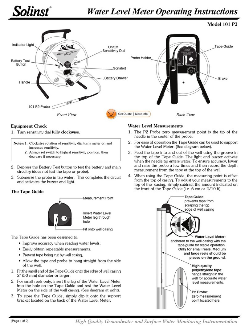
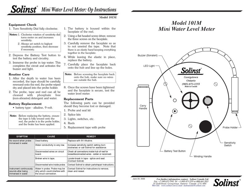
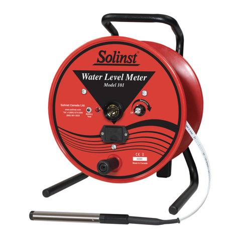
  9. Solinst 101 Parts list manual

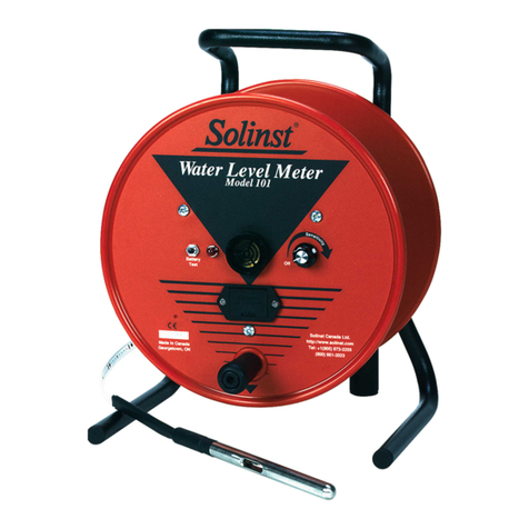
Solinst 101 Parts list manual

Replacing all Electronics
Complete Electronics Kit (#103558) Includes:
• Mk2 Circuit Board Assembly (with push-release fittings)
– Wiring, Sensitivity Switch and Knob, and Test Button
• Red LED Indicator Light with Terminals
• Sonalert
• Battery Tray, 4 x Screws, 2 x Nuts
• 9V Alkaline battery
Note: These instructions explain how to replace each electronic
component either all at once or separately as required.
Tools and Materials Needed
1. Required Repair Kit
2. Phillips Screwdriver
3. Small Flat Screwdriver (3 mm (1/10")
4. 10 mm (3/8") Wrench
5. Pliers
6. Wire Cutters
7. Wire Strippers
8. Solder Wire with Flux
9. Soldering Iron
1. Remove the battery from the meter. Undo the three screws
holding the faceplate to the reel. Remove the faceplate.
2. If this is an Mk1 Water Level Meter, disconnect the Molex
connector that connects the circuit board to the tape. If
this is an Mk2 Water Level Meter, press down on the white
terminals of the push-release fittings on the circuit board
and pull out to remove the tape leads.
3. From the front of the faceplate, use the wrench to unscrew
the nut holding the test button and push the button back
out of the faceplate.
4. Cut the red and black wires connected to the light, and
push the light out through the front of the faceplate.
5. Use the Phillips screwdriver to undo the two screws from
the battery tray. If this is an Mk1 Water Level Meter, cut
the red and black wires from the battery tray.
If this is an Mk2 Water Level Meter, simply pull the quick-
connect fittings off of the terminals on the battery tray.
Remove the battery tray from the faceplate.
6. Use the small flat screwdriver to unscrew the small brass
screw on the side of the sensitivity knob. Remove the
sensitivity knob. Use the pliers to unscrew the nut holding
the sensitivity switch and remove the switch from the
faceplate.
7. Unscrew the Sonalert retaining ring from the front of the
faceplate and remove the old Sonalert and circuit board
assembly from the faceplate.
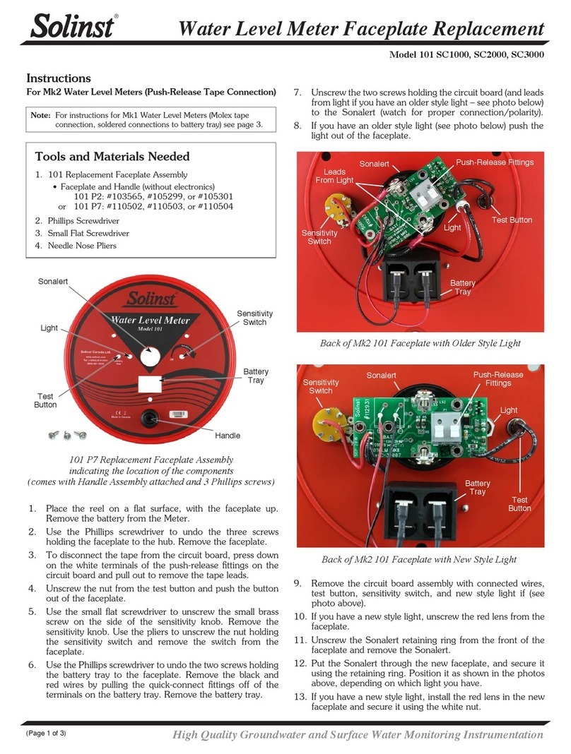
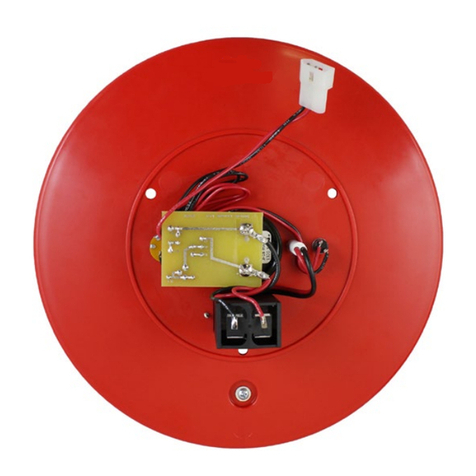
Back of Mk1 Water Level Meter Faceplate
Back of Mk2 Water Level Meter Faceplate
(with push-release ttings)
Complete Electronics Kit (#103558)
Sonalert
Sensitivity
Switch
Light
Battery
Tray
Test Button
Sensitivity
Switch
Sonalert
Light
Battery
Tray
Test Button
Molex
Connector
Push-Release
Fittings
High Quality Groundwater and Surface Water Monitoring Instrumentation
(Page 1 of 6)
Water Level Meter Complete Electronics Replacement
Model 101/102
8. Insert the new battery tray through front of the faceplate.
Use the two screws (bolts and nuts where required) to
secure the tray to the faceplate.
15. Insert the test button through the opening in the faceplate,
and secure it in place using the nut.
16. Insert the sensitivity switch through the faceplate with the
three connection prongs positioned towards the battery
drawer, slightly towards the centre of the reel. Tighten the
nut. Fasten the sensitivity knob on the front of the switch
using the brass screw.
17. Connect the black wire with quick-connect fitting to the
negative terminal on the battery tray. Connect the red wire
with quick-connect fitting to the positive terminal.
18. Connect the tape to the new circuit board assembly:
a) If this is a Mk2 Water Level Meter, press down
on the white terminals on the circuit board and insert
the tape leads. Release the terminals and the leads
should be secured. The lead on the bottom of the tape
(numbers facing up) is inserted into the terminal with a
white square below it on the circuit board.
b) If this is an Mk1 Water Level Meter, with a Molex
connector on the tape leads, remove the Molex
connector by pushing out the two pins. Cut each pin
in half (see image below for correct location). Use
pliers to flatten the remainder of the pins against the
tape lead, so it fits easily into the terminals on the
circuit board. Connect each tape lead to the new
circuit board assembly, as described above in step a.
Note: To secure the battery tray, the #4 x 1/2” Phillips Screws are
for plastic reels, while the #4-40 x 1/2” Phillips Bolts and Nuts
are for metal reels.
9. Put the new Sonalert through the faceplate, and secure
it using the retaining ring. Use the photo of the fully
assembled faceplate below as a reference for its position.
The negative terminal should be closest to the battery tray.
Sonalert
Sensitivity
Switch
Light
Battery
Tray
Test Button
10. Thread the leads of the LED light assembly through the
front of the faceplate and snap the light in place.
11. Unscrew the two screws from the Sonalert.
12. Use the two screws to connect the black wire (-ve terminal)
and red wire (+ve terminal) from the light to the outside
of the corresponding terminals on the Sonalert. Do not
tighten the screws all the way.
13. Slide the circuit board assembly in position on top of the
Sonalert, ensuring the sides marked +ve and -ve are lined
up with the corresponding terminals on the Sonalert.
14. To connect the circuit board, wrap the two bare wires from
the circuit board around the screws, between the light and
Sonalert terminals. Start by bringing the wires underneath
the screws (see photo below). Tighten the two screws.
Remove the Pins from the Tape Molex Connector (Mk1)
Molex
Connector
Wrap bare wires
from circuit board
around screws
High Quality Groundwater and Surface Water Monitoring Instrumentation
Water Level Meter Complete Electronics Replacement
(Page 2 of 6)
Replacing the Circuit Board (#102977)
Mk2 Circuit Board Assembly (with push-release fittings) includes:
• Wiring, Sensitivity Switch and Test Button
Release the White Terminals and the Leads Should be Secured.
Cut the Pins on Each Tape Lead in Half (as shown)
Press Down on the White Terminals on the Circuit Board and
Insert the Tape Leads
19. Install the new battery.
20. With the probe in a glass of tap water, turn the Water Level
Meter to the ‘ON’ position. If the connections are correct
the buzzer and light will activate. If the buzzer or light do
not activate, check all connections and the polarity of the
battery.
21. Reattach the faceplate to the reel using the three screws.
Sonalert
Sensitivity
Switch
Light
Battery
Tray
Test Button
1. Remove the battery. Unscrew the three screws and remove
the faceplate.
2. If this is an Mk1 Water Level Meter, disconnect the Molex
connector that connects the circuit board to the tape. If
this is an Mk2 Water Level Meter, press down on the white
terminals of the push-release fittings on the circuit board
and pull out to remove the tape leads.
3. If this is an Mk1 Water Level Meter, cut the red and black
wires from the battery tray. If this is an Mk2 Water Level
Meter, simply pull the quick-connect fittings off of the
terminals on the battery tray.
4. From the front of the faceplate, use the wrench to unscrew
the nut holding the test button and push the button back
out of the faceplate.
5. Use the small flat screwdriver to unscrew the small brass
screw on the side of the sensitivity knob. Remove the
sensitivity knob. Use the pliers to unscrew the nut holding
the sensitivity switch and remove the switch from the
faceplate. Save the knob and screw to be used with the
new sensitivity switch.
6. Watch for proper connection/polarity on the Sonalert and
remove the two screws to disconnect the old circuit board
assembly (and the wires connected to the light) from the
Sonalert.
7. If this is an Mk1 Water Level Meter, use pliers to bend
the terminals on the Sonalert, so they are straight up from
the Sonalert (to accommodate the new circuit board in
between the terminals). Loosen the Sonalert retaining nut
on the front of the faceplate, so you can reposition the
Sonalert as shown in the photo below (negative terminal
next to the battery tray).
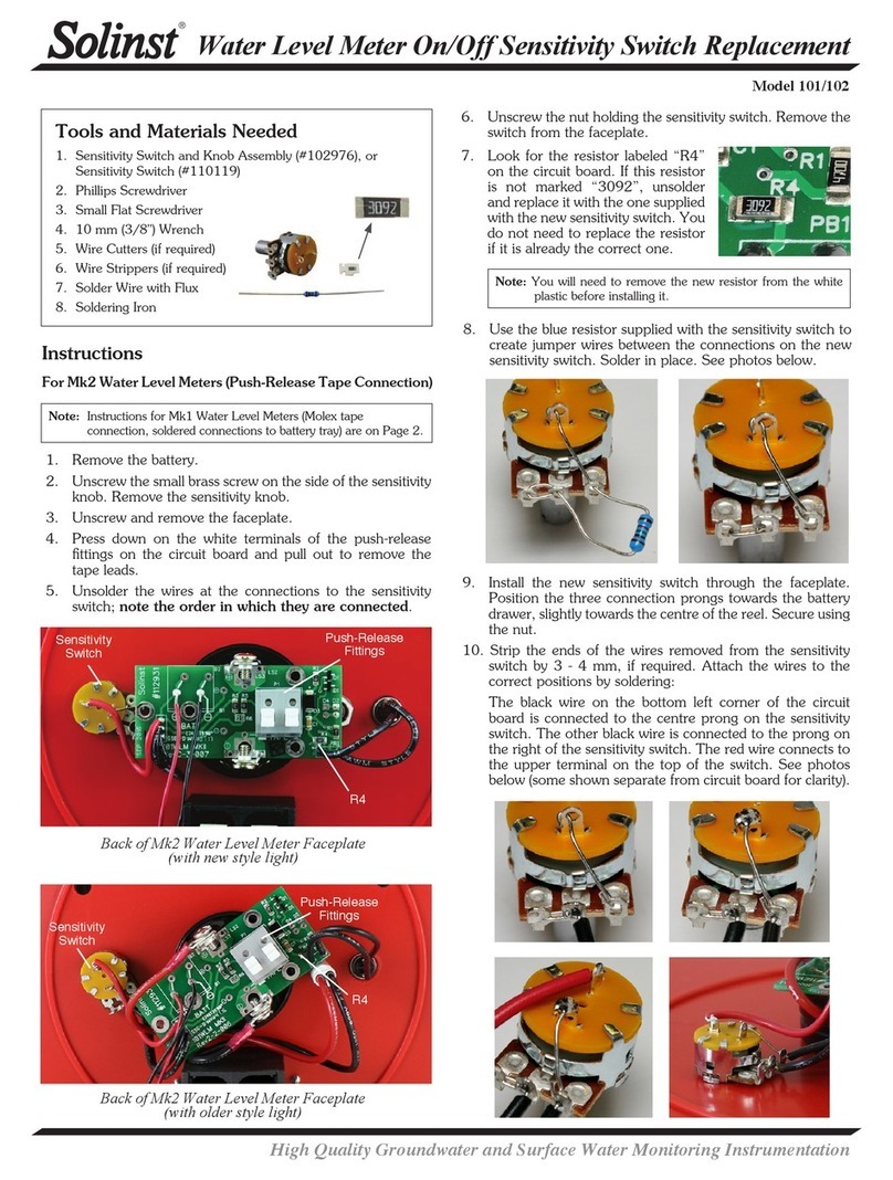
8. Follow Steps 12- 14 on Page 2 to connect the new circuit
board, and reconnect the light.
Mk2 Circuit Board Showing Wire Connections
Square
High Quality Groundwater and Surface Water Monitoring Instrumentation
Water Level Meter Complete Electronics Replacement
(Page 3 of 6)
Replacing the Test Button (#109080)
1. Take out the battery, and remove the faceplate by
unfastening the three screws.
2. If this is an Mk1 Water Level Meter, disconnect the Molex
connector that connects the circuit board to the tape. If
this is an Mk2 Water Level Meter, press down on the white
terminals of the push-release fittings on the circuit board
and pull out to remove the tape leads.
3. Cut off the wires at the connections to the test button and
strip the wires.
4. Unscrew the old test button and remove from the faceplate.
5. Install the new test button in the faceplate and secure with
the nut.
6. Attach the wires to the new test button by soldering (for the
Mk1 Water Level Metes, ensure the red wire is soldered to
the positive terminal on the button, and the black wire to
the negative terminal.)
7. Reconnect the tape to the circuit board. For Mk1 Water
Level Meters, you will use the Molex connector. If this
is an Mk2 Meter, press down on the white terminals on
the circuit board and insert the tape leads. Release the
terminals and the leads should be secured. The lead on the
bottom of the tape (numbers facing up) is inserted into the
terminal with a white square below it on the circuit board.
8. Replace the faceplate by fastening the three screws.
Replace the battery.
Test Button Connections
– Mk2
Test Button Connections –
Mk1
Test
Button
Test
Button
9. Insert the test button through the opening in the faceplate,
and secure it in place using the nut.
10. Insert the sensitivity switch through the faceplate with the
three connection prongs positioned towards the battery
drawer, slightly towards the centre of the reel. Tighten the
nut. Fasten the sensitivity knob on the front of the switch
using the brass screw.
11. Connect the black wire with quick-connect fitting to the
negative terminal on the battery tray. Connect the red wire
with quick-connect fitting to the positive terminal.
Sonalert
Sensitivity
Switch
Light
Battery
Tray
Test Button
12. Connect the tape to the new circuit board assembly, as
described in Step 18, on Page 2.
13. Install the battery.
14. With the probe in a glass of tap water, turn the Water Level
Meter to the ‘ON’ position. If the connections are correct
the buzzer and light will activate. If the buzzer or light do
not activate, check all connections and the polarity of the
battery.
15. Reattach the faceplate to the reel using the three screws.
Mk2 Circuit Board Showing Wire Connections
High Quality Groundwater and Surface Water Monitoring Instrumentation
Water Level Meter Complete Electronics Replacement
(Page 4 of 6)
Replacing the Light (#106660)
1. Remove the battery. Unscrew and remove the faceplate.
2. If this is an Mk1 Water Level Meter, disconnect the Molex
connector that connects the circuit board to the tape. If
this is an Mk2 Water Level Meter, press down on the white
terminals on the circuit board and pull out to remove the
tape leads.
3. Unscrew the two screws holding the wires from the light,
to/through the circuit board and the Sonalert (watch for
proper polarity).
4. Push the old light out and put the new light through the
faceplate.
5. Reconnect the two wires, using screws to the circuit board
and the Sonalert.
6. Reconnect the tape to the circuit board. For Mk1 Water
Level Meters, you will use the Molex connector. If this
is an Mk2 Meter, press down on the white terminals on
the circuit board and insert the tape leads. Release the
terminals and the leads should be secured. The lead on the
bottom of the tape (numbers facing up) is inserted into the
terminal with a white square below it on the circuit board.
7. Replace the faceplate, with three screws. Replace the
battery.
Light Connections –Mk2 Light Connections – Mk1
Replacing the Sonalert (#109075)
1. Remove the battery. Unscrew and remove the faceplate.
2. If this is an Mk1 Water Level Meter, disconnect the Molex
connector that connects the circuit board to the tape. If
this is an Mk2 Water Level Meter, press down on the white
terminals of the push-release fittings on the circuit board
and pull out to remove the tape leads.
3. Unscrew the Sonalert retaining ring from the front of the
faceplate. Push out the old Sonalert.
4. Unscrew the two screws holding the Sonalert to the circuit
board (watch for proper connection/polarity). Remove the
Sonalert from the circuit board.
5. For Mk1 Water Level Meters, use pliers to bend the
connection terminals on the new Sonalert inwards by 90º.
Use the old Sonalert you are replacing as a reference.
6. Insert the new Sonalert through the faceplate, and fasten
the Sonalert retainer ring until finger tight. Ensure the
Sonalert is positioned as shown below.
Light/Circuit Board
Connections –Mk2
Light/Circuit Board
Connections – Mk1
7. Use the two screws to reconnect the wires from the light,
and the circuit board to the Sonalert. Make sure the wires
from the light and circuit board are connected to the
correct terminals.
8. Reconnect the tape to the circuit board. For Mk1 Water
Level Meters, you will use the Molex connector. If this
is an Mk2 Meter, press down on the white terminals on
the circuit board and insert the tape leads. Release the
terminals and the leads should be secured. The lead on the
bottom of the tape (numbers facing up) is inserted into the
terminal with a white square below it on the circuit board.
9. Replace the faceplate, with three screws. Replace the
battery.
Sonalert
Sonalert
High Quality Groundwater and Surface Water Monitoring Instrumentation
Water Level Meter Complete Electronics Replacement
(Page 5 of 6)
Note: To gain better access to the sensitivity switch on Mk1 Water
Level Meters, you may want to unscrew the two screws holding
the circuit board to the Sonalert, in order to move the circuit
board out of the way.
Replacing the On/Off Sensitivity Switch
Sensitivity Switch and Knob Assembly (#102976), or
Sensitivity Switch (#110179)
1. Remove the battery.
2. Unscrew the small brass screw on the side of the sensitivity
knob. Remove the sensitivity knob.
3. Unscrew and remove the faceplate.
4. If this is an Mk1 Water Level Meter, disconnect the Molex
connector that connects the circuit board to the tape. If
this is an Mk2 Water Level Meter, press down on the white
terminals of the push-release fittings on the circuit board
and pull out to remove the tape leads.
5. Unsolder the wires at the connections to the sensitivity
switch; note the order in which they are connected.
For the Mk2 Water Level Meters, one of the black wires is
soldered to two prongs on the sensitivity switch - ensure to
unsolder the wire from both (try to keep the full length of
stripped wire).
6. Unscrew the nut holding the sensitivity switch. Remove the
switch from the faceplate.
7. Install the new sensitivity switch through the faceplate. For
Mk2 Water Level Meters, position the three connection
prongs towards the battery drawer, slightly towards the
centre of the reel. For Mk1 Water Level Meters, position
the three connection prongs opposite the battery tray and
slightly towards the centre of the reel. Secure using the nut.
Sensitivity Switch
Connections –Mk2 Sensitivity Switch
Connections – Mk1
8. Strip the wires if required. Attach the wires to the correct
positions by soldering:
For Mk1 Water Level Meters, the two red wires on the
bottom of the circuit board are connected to the first two
connections on the sensitivity switch. The black wire on the
bottom of the circuit board is connected to the third prong
on the sensitivity switch. The black wire closest to the top
of the circuit board is attached to the prong on the top of
the sensitivity switch. The other black wire connected to
the top of the sensitivity switch is connected to the negative
terminal on the battery tray (use the diagram on the left for
reference).
For Mk2 Water Level Meters, the black wire on the bottom
left corner of the circuit board is connected to the centre
prong on the sensitivity switch. The black wire with the
long stripped section goes through the prong on the right
of the sensitivity switch and connects to the prong on the
top of the switch. The red wire connects to the upper
terminal on the top of the switch.
9. Reconnect the tape to the circuit board. For Mk1 Water
Level Meters, you will use the Molex connector. If this
is an Mk2 Meter, press down on the white terminals on
the circuit board and insert the tape leads. Release the
terminals and the leads should be secured. The lead on the
bottom of the tape (numbers facing up) is inserted into the
terminal with a white square below it on the circuit board.
10. Replace the faceplate, with three screws.
11. Fasten the sensitivity knob using the brass screw.
12. Replace the battery.
Printed in Canada
December 16, 2016
(#108429)
(Page 6 of 6)
For further information contact: Solinst Canada Ltd.
Fax: +1 (905) 873-1992; (800) 516-9081 Tel: +1 (905) 873-2255; (800) 661-2023
35 Todd Road, Georgetown, Ontario Canada L7G 4R8
Web Site: www.solinst.com E-mail: [email protected]
®Solinst is a registered trademark of Solinst Canada Ltd.

This manual suits for next models

1

Other Solinst Measuring Instrument manuals

Solinst 101 Operating and safety instructions

Solinst

Solinst 101 Operating and safety instructions

Solinst 107 Mk2 User manual

Solinst

Solinst 107 Mk2 User manual

Solinst 122M User manual

Solinst

Solinst 122M User manual

Solinst 101 P2 Operating and safety instructions

Solinst

Solinst 101 P2 Operating and safety instructions

Solinst 101 P2 User manual

Solinst

Solinst 101 P2 User manual

Solinst 101M User manual

Solinst

Solinst 101M User manual

Solinst LevelSender 5 User manual

Solinst

Solinst LevelSender 5 User manual

Solinst 101 P7 User manual

Solinst

Solinst 101 P7 User manual

Solinst 102 Operating and safety instructions

Solinst

Solinst 102 Operating and safety instructions

Solinst 101 Operating and safety instructions

Solinst

Solinst 101 Operating and safety instructions

Solinst 102M User manual

Solinst

Solinst 102M User manual

Solinst 122M User manual

Solinst

Solinst 122M User manual

Solinst Levelogger Series User manual

Solinst

Solinst Levelogger Series User manual

Solinst 615 ML User manual

Solinst

Solinst 615 ML User manual

Solinst Levelogger 3001 Use and care manual

Solinst

Solinst Levelogger 3001 Use and care manual

Solinst 9700 SolSat 5 User manual

Solinst

Solinst 9700 SolSat 5 User manual

Solinst 122 User manual

Solinst

Solinst 122 User manual

Solinst 102 User manual

Solinst

Solinst 102 User manual

Solinst 101 User manual

Solinst

Solinst 101 User manual

Solinst 101 Operating and safety instructions

Solinst

Solinst 101 Operating and safety instructions

Solinst 101 User manual

Solinst

Solinst 101 User manual

Solinst 101B User manual

Solinst

Solinst 101B User manual

Solinst 101D User manual

Solinst

Solinst 101D User manual

Solinst 107 Mk2 User manual

Solinst

Solinst 107 Mk2 User manual

Popular Measuring Instrument manuals by other brands

NAVIS WR3-B manual

NAVIS

NAVIS WR3-B manual

Sola METRON 60 BT operating instructions

Sola

Sola METRON 60 BT operating instructions

Datum 4040B operating manual

Datum

Datum 4040B operating manual

Agilent Technologies 3200D operating guide

Agilent Technologies

Agilent Technologies 3200D operating guide

Sealey TA201 instructions

Sealey

Sealey TA201 instructions

AR FL7040 Operating and service manual

AR

AR FL7040 Operating and service manual

Altana BYK byko-visc RT Lite Short instructions

Altana

Altana BYK byko-visc RT Lite Short instructions

Thornton 770MAX Firmware Upgrade Instructions

Thornton

Thornton 770MAX Firmware Upgrade Instructions

CPS IAQPRO SmartAir Quick Start and Troubleshooting Guide

CPS

CPS IAQPRO SmartAir Quick Start and Troubleshooting Guide

Auper TM6400 Installation and programming guide

Auper

Auper TM6400 Installation and programming guide

NRD Staticmaster 521AE Installation, operation and maintenance guide

NRD

NRD Staticmaster 521AE Installation, operation and maintenance guide

KROHNE optiplex 1300 c Handbook

KROHNE

KROHNE optiplex 1300 c Handbook

Ametek Chandler Engineering 4207D operating manual

Ametek

Ametek Chandler Engineering 4207D operating manual

Vega VEGAPULS SR 68 operating instructions

Vega

Vega VEGAPULS SR 68 operating instructions

Rohde & Schwarz R&S NRPM user manual

Rohde & Schwarz

Rohde & Schwarz R&S NRPM user manual

Endress+Hauser Promonitor NRF560 operating instructions

Endress+Hauser

Endress+Hauser Promonitor NRF560 operating instructions

Mechatron DPG-2 user manual

Mechatron

Mechatron DPG-2 user manual

Trotec SL3000 manual

Trotec

Trotec SL3000 manual

manuals.online logo
manuals.online logoBrands
  • About & Mission
  • Contact us
  • Privacy Policy
  • Terms and Conditions

Copyright 2025 Manuals.Online. All Rights Reserved.