SI Nano Box User manual

INSTALLERS: Please leave this manual with the owner.
24v DC - Zigbee / RTS
Nano Box
Installation Instructions
Doc. # 400024


PARTS LIST
Parts list - Nano Box - 24v DC - RTS 1
Shades
Leveling Shims
(4 per shade)
Installation Remotes
(1 per RTS shade)
Wall Brackets
Spacer Blocks (optional - 4 per shade)
Terminal Block
Brackets
275 Box
375 Box
475 Box
Terminal Blocks
Screws Included
(3 per Bracket)
Longer Screws Included
Included remotes form factor may
vary, however RF functionality and
performance is consistent.”
OR
Please note all the Serial No.s on your Shade motors.
See the last page on these instructions.

2
Spacer Blocks - used to clear an obstruction in the fabric path.
Leveling Shims - used if the window frame is out of level.
Connect to shade brackets before installation
Note: do not use more than 2 leveling shims per bracket.
Note: Do not use more than 4 spacer blocks per bracket.
Connect spacer blocks to shade brackets before installation.
SPACER BLOCKS AND LEVELING SHIMS (OPTIONAL)
Spacer blocks and Leveling Shims

3. Make sure the wall bracket lever is down (may already be down).
INSTALLATION
1. Terminate pre-wire with the supplied terminal block.
Not
Used
Data For 24vDC Only
Header
Jamb
24
24
+
Installation - Nano Box - 24v DC - RTS 3
Proper position for
installing Box
2. Box bracket position is recommended 2”-4” from end caps.
2” - 4” 2” - 4”

4. Install terminal block bracket between jamb and wall bracket on the motor side using the
supplied screws
Jamb
Jamb
Header
Terminal block bracket must be on motor side.
4” - 6” 4” - 6”
INSTALLATION
Installation - Nano Box - 24v DC - RTS 4
5. Connect the shade and pre-wire connectors, then snap into the terminal block bracket

INSTALLATION
6. Hang shade onto wall brackets and center in opening
Installation - Nano Box - 24v DC - RTS 5
7. Use thumb to lock shade in place

Wiring - Nano Box - 24v DC - RTS
WIRING
24v DC
For guaranteed motor performance the supplied voltage for 24v motors must be 24v DC. See
the table below for maximum wire lengths.
If the motors are powered using a Kartos connect the motors to the “+v” and “-v” ports on the
terminal blocks.
Wire Gauge (AWG)
14
16
18
Maximum Supported Wire Length (FT.)
250
150
100
V+ Positive 24vDC
V- Negative 24vDC
6
2 Conductor Cable for each
Zigbee/RTS LV motor
V+
V-
V+
V-
V+
V-
V+
V-

Programming - Zigbee
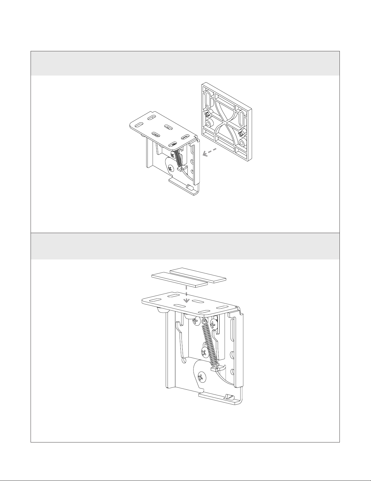
The lower limit of every shade is preprogrammed to 1/2” from the bottom of the window. After
installing each shade, follow these steps to adjust the lower limit:
STEP 2 - Assign shades to groups :
All grouping of devices is completed within the TaHoma application:
1. Open the TaHoma application and navigate to the conguration tab.
2. Press the + symbol in the upper right corner.
3. Choose the Zigbee device type.
4. Select “Add Zigbee Group”.
5. Label the group.
6. Select the devices you would like to be included in this group.
STEP 3 - Pair devices or groups with a remote:
All pairing of devices and groups to remotes is completed within the TaHoma application. In
order to pair more than one shade to a channel, a group must be created rst.
1. Open the TaHoma application and navigate to the conguration tab.
2. Press the chain/link button next to the remote being congured.
3. Select the shade or group to pair from the list and deselect any other devices.
4. Quick press the programming button on the back of the remote and click OK in the application
to conrm.
NOTE: Each Zigbee Situo remote channel will be capable of pairing to a group containing up to 20 motors.
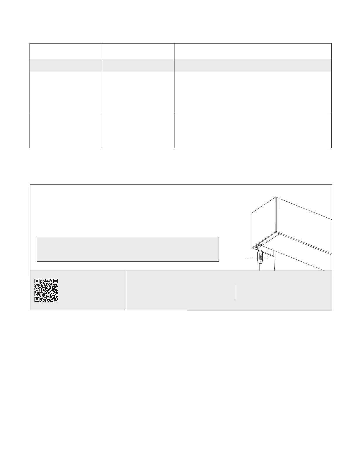
PROGRAMMING STEPS
(TaHoma/LinkPro Z must be plugged in and on the network)
Step 1: Fine tune lower limit.
Step 2: Assign shades to groups and remotes.
Step 3: Pair devices and groups with remotes.
STEP 1 - Fine tuning lower limit :
1. Click on the 3 dots in the lower right hand corner of the TaHoma app.
Note: You may see a pop-up warning window which could damage the shade.
2. In settings click on advanced settings.
3. Select the shade you want to set the limits to.
4. You only want to select and adjust the lower limit.
Note: Do not set upper limit or change rotation.
5. Press the down button in the app to move the shade to the Factory set lower limit.
6. Click Next.
7. Now make up or down adjustments to shade using the Up / Down increments. Each (button
press) adjustment can take a couple seconds, to execute. Once you are satised with the new
lower limit, press save Limit.
PROGRAMMING

Tech Support: 512.832.6939
For Zigbee
Problem Possible Cause Action to Take
TaHoma LED is Red. No internet
connectivity.
Check network connection to the internet, and ensure
the TaHoma is properly connected via ethernet or
Wi.
Shade won’t operate. Low-voltage power
supply
Verify wiring, terminations and AC power connections
to your power supply.
TROUBLESHOOTING
TROUBLESHOOTING WITH SUPPORT
With our Support team guidance, you may be instructed to
press the motor programming button using a thin tool (e.g. a
paperclip). If instructed, pressing this button for 2 seconds, can
take the motor out of delivery mode and will result in 1 jog.
Note: Under no circumstances, should you hold this
programming button for more than 2 jogs.
Technical Support: 512.832.6939 screeninnovations.com
Please use this QR Code
to access the updated
installation instructions
thin
tool

Programming - RTS 7
PROGRAMMING
Each RTS Nano shade includes an installation remote that is used to adjust limits and program
group controls. These installation remotes are uniquely numbered to the shade they are paired
with. The lower limit of every shade is preprogrammed to ½” from the bottom of the window.
After installing each shade, follow these steps to adjust the lower limit:
STEP 2 - Assign shades to groups :
Next, program group controls. To pair with a permanent transmitter
such as a multichannel Telis or DecoFlex, follow these steps.
1. Press and hold the program button on the back of the installation
remote until the shade jogs.
2. Select the channel where you want to create a group, then bump
(do not hold down) the program button on the back of the remote -
the shade will jog.
3. Both remotes now control the shade.
4. Continue doing this with each shade until all shades are
programmed in the desired groups.
NOTE: Each RTS motor can be paired with 12 unique transmitters.
PROGRAMMING STEPS (must follow in order)
Step 1: Fine tune lower limit
Step 2: Assign shades to groups
Step 3: Pair groups to control system (Mylink, LinkPro)
1. Beginning with the rst shade, pull plastic tab from remote and press allowing shade to run
to lower limit set at the factory.
2. When shade has stopped, adjust the lower limit by holding and simultaneously until the
shade jogs.
3. Use or to move the shade to the desired lower limit.
4. Hold the button until the shade jogs again.
5. Repeat this procedure at each window until all shades have lower limits set to desired positions.
1. Download the myLink app.
2. Pair the grouped shades with LinkPro or MyLink according to the instructions in the myLink app.
STEP 1 - Fine tuning lower limit :
STEP 3 - Pair Groups to control system (LinkPro, myLink) :
Warning: Do not
attempt to use any
installation remote until all
the shades are installed.
hold the button
until the shade jogs
(light on the motor
turns green).
Installation
Remote
Permanent
Remote
Bump
(do not hold)

TROUBLESHOOTING
For RTS
Problem Possible Cause Action to Take
Shade won’t operate. Motor is not powered.
Ensure that 24Volt motors have 24v DC supply and
that the polarity is correct.
Remote button presses
are too short.
When operating an RTS remote hold the buttons
down for at least 2 seconds.
The remote is being
used out of range.
Move within 30ft. of the shade. If the issue persists,
adjust the antenna to a new position, and make sure
the antenna does not touch metal.
The remote battery is
out of place or drained.
Check that the red LED on the remote ashes when
buttons are pressed. On the installation remote, pry
off the back by hand and ensure the battery is fully
seated in the battery tray. If the remote remains
unresponsive, replace the battery with a CR2430 3V
lithium cell.
Troubleshooting - RTS 8
Tech Support: 512.832.6939
Technical Support: 512.832.6939 screeninnovations.com
Please use this QR Code
to access the updated
installation instructions
and related documents.

MOTOR SERIAL NO.S
Motor Serial No.s
Please keep a note of all the Serial No.s on your shade motors. OR for larger shade orders,
refer to your Sales Order document for the list.
Room
Room
Shade 1
Shade 1
Shade 3
Shade 3
Shade 5
Shade 2
Shade 2
Shade 4
Shade 4
Shade 6
9


1.
2.
3.
4.
5.
6.
7.
8.
9.
10.
11.
12.
13.
14.
15.
16.
17.
18.
Notes
NOTES

Screen Innovations
9715-B Burnet Rd, Suite 400 Austin, TX 78758
512.832.6939
www.screeninnovations.com
400024 Ι v. 1.7 Ι 17 December 2021
Other manuals for Nano Box
5
Other SI Window Blind manuals
Popular Window Blind manuals by other brands

Draper
Draper FlexShade NEXD INSTRUCTIONS INSTALLATION & OPERATION

MADECO
MADECO INST-792002 quick start guide

Smith & Noble
Smith & Noble Rod Step by step installation instructions

rollease acmeda
rollease acmeda Automate FT instructions

Smith & Noble
Smith & Noble Faux Wood Blinds Step by step installation instructions

WAREMA
WAREMA PB Instructions for installation, use and maintenance