MHZ s-enn SN 72/1 User manual

Metal blind s_enn SN 72/1, SN 72/2
Installation instructions I Edition 03.2022

Page 2 Subject to technical changes I Edition 03.2022
Installation instructions for metal blind s_enn SN 72/1, SN 72/2
Table of contents
Safety information for the installation 3 - 6
Installation instructions 7 - 20
Record of delivery 23
Page
Installation instructions for metal blind s_enn SN 72/1, SN 72/2
Page 3Subject to technical changes I Edition 03.2022
1. Reading the installation and operating instructions
The installation and operating instructions must be read prior
to installation and then duly followed. Any failure to do so absolves
the manufacturer of any liability.
1.1. Safety and warning notes for the installation instructions
Safety notes can be found throughout the text. They are marked
with various symbols and text:
Important safety note:
Notes that are important for the functioning of the product and can
result in serious injury or death if they are not observed are marked
with this warning triangle.
Important safety note:
Notes that are important for the functioning of the product and
that represent a risk of electrocution that can result in serious injury
or death if they are not observed are marked with this warning
triangle.
2. Qualications
These installation instructions are aimed exclusively at qualied
installers with extensive knowledge in the following areas:
n Health and safety at work and accident prevention regulations
n Working with ladders and scaffolding
n Handling and transporting long, heavy components
n Working with tools and machines
n Attaching fasteners
n Assessing the building fabric
n Commissioning and operating the product
In the absence of any of these qualications, a specialist instal-
lation company must be employed to install the product.
Electrical work:
The permanent electrical installation must be carried out by a
qualied electrician in accordance with statutory and local regula-
tions (VDE 100). The enclosed installation instructions for the electri-
cal devices supplied with the product must be followed.
The unit is to be protected with an upstream
FI circuit breaker in accordance with VDE regulations.
3. Goods receipt
The delivery must be inspected immediately upon receipt for any
damage sustained in transit. In addition, the contents of the ship-
ment must be checked against the delivery note.
4. Transport
The permissible axle loads and the permissible total weight of
the means of transport must not be exceeded. Loading can affect
the vehicle’s handling.
The goods being transported are to be tied down and properly
secured. The metal blind packaging must be kept dry.
Wet packaging may disintegrate, causing accidents. Packaging
opened for the purpose of inspecting incoming goods must be
properly taped up again for further transportation.
After unloading, the metal blind should be transported to the
installation site right-side-up and in the proper installation posi-
tion, so that it will not have to be manoeuvred later in tight spaces.
Attention must be paid to the note on the box indicating position
and side.
5. Lifting with ropes
If the metal blind needs to be lifted to a higher position using
ropes, the metal blind should be
n taken out of the packaging,
n fastened to the hoisting ropes in such a way that it cannot
slip off
n and lifted smoothly in a horizontal position.
The same applies to taking down the metal blind.
6. Installation
Prior to installation, check the load-carrying capacity of the
sub-construction.
It is important to check the structural properties of the glass facade
construction prior to installation. In addition, ensure that the
fastening screws are screwed directly into the supporting structure
and that, in the event of wind, there is no connection to the glazing
bead, as this could result in stress cracks. If this is not feasible, the
installation must not be performed.
If there is any doubt, the manufacturer of the glass facade construc-
tion must be consulted.
Important safety information for the installation
!
!
!
!
!
!
!

Page 4 Subject to technical changes I Edition 03.2022
Installation instructions for metal blind s_enn SN 72/1, SN 72/2
Caution:
Supplied without ttings (accessories).
The installer must select ttings that are suitable for the particular
sub-construction.
The installer is solely liable for ensuring that the ttings are suitable
for the respective brickwork and that the installation work is per-
formed properly. The respective installation notes from the manu-
facturer of the glass facade construction must be adhered to!
7. Fasteners
The metal blind fulls the requirements of the wind resistance
class specied in the CE conformity mark (see operating instruc-
tions). When installed, these requirements are only met if:
n The metal blind is installed using the type and number of
brackets recommended by the manufacturer
n The metal blind is suitably mounted to the sub-construction
n The wind resistance class to be achieved depends on the
installation substructure and unit width
n The conditions to be complied with to ensure that the perfor
mance specications are fullled are based on static loads and
do not take account of any dynamic effect of repeatedly
applied loads (turbulence) to which the metal blind and frame
are exposed during actual use. The static pressure can there
fore not be used to determine how to anchor the metal blinds
to the building.
Important safety information for the installation
Maximum permissible wind speed at which the unit can be used
Resistance to wind load
The wind classes dened by DIN EN 13659 do not permit any con-
clusions to be drawn on usability (extending/retracting, intermedi-
ate positions, etc.) under actual wind loads. The manufacturer must
therefore dene the maximum speed above which the metal blind
must be retracted taking into consideration the installation situation
and the blind clearance. This wind speed must be stated in the tech-
nical documentation (e.g. operating instructions). The conditions to
be complied with to ensure that the performance specications are
fullled are based on static loads and do not take account of any
dynamic effect of repeatedly applied loads (turbulence) to which
the metal blind and frame are exposed during actual use. The static
pressure can therefore not be used to determine how to anchor the
metal blinds to the building.
The substructure/distance to the facade/height/corner situation also
has an inuence on the maximum possible wind speed and is not
taken into account in the standard (DIN EN 1932:2013-09 External
blinds and shutters – Resistance to wind loads – Method of testing
and performance criteria) although these factors have a signicant
impact on the product’s resistance to wind loads.
Note regarding applicability
The wind speeds used in the following table only apply with win-
dows closed and not in corner situations. Similarly, the positioning
and number of wind monitors used are of vital importance in se-
lecting the appropriate wind speed for the building in question. In
particular, the building’s geometry and location must be taken into
consideration. For this reason, it is essential to consult the specialist
planner in such situations.
Maximum wind speed at which the unit can be used in m/s
Note:
Please note that the specications on the maximum wind speed at
which the unit can be used relate to installation as intended directly
on the facade. In the case of installation options deviating from the
above, please contact MHZ for the necessary specications.
Unit width (mm)
Unit
height
(mm)
1000
1500 2000 2700
1000 16 16 16 12
1500 16 16 16 12
2000 16 16 16 12
2500 16 16 16 12
3000 16 16 16 12
3500 14 14 14 10
4000 14 14 14 10
4500 14 14 14 10
MHZ Hachtel GmbH & Co. KG
Sindelfinger Straße 21, D-70771 Leinfelden-Echterdingen
Germany
2021
LE-012/2
*
The wind resistance class depends on the application width.
The declared performance applies only to the product.
After installation, the installation base may result in a lower
performance.
Wind resistance class:
Class 3 up to max. 11,9 m/s or up to max. 43 km/h
Class 4 up to max. 16,1 m/s or up to max. 58 km/h
EN 13659:2004+A1:2008
s_enn SN 72/1, SN 72/2, Modell 48-1180
CE product marking
External installations on buildings
and other structures
Wind resistance *:
Units up to 2000 mm width = Class 4
Units up to 2700 mm width = Class 3
!

Installation instructions for metal blind s_enn SN 72/1, SN 72/2
Page 5 Subject to technical changes I Edition 03.2022
8. Climbing aids
Climbing aids must not be attached to or leant against the
metal blind. They must be steady and provide adequate grip. Use
only climbing aids with a sufciently high load-bearing capacity.
Only approved climbing aids (ladders) may be used.
9. Fall protection equipment
There is a risk of falling when working at height.
Appropriate fall protection equipment must be used.
10. Electrical connection
The metal blind may only be connected if the
electric drive’s specications match the electricity source (see oper-
ating instructions).
The installation notes included with the electrical components must
be followed.
The unit is to be protected with an upstream
FI circuit breaker in accordance with VDE regulations.
Only cables and connectors with a minimum protection class
of IP 54 should be used to supply power.
11. Intended use
Metal blinds should only be used for the purpose dened for
them in the operating instructions.
Changes, such as attachments and modications, not intended by
the manufacturer may only be carried out with the manufacturer’s
written consent.
Applying additional loads to the metal blind by attaching objects
can result in it becoming damaged or falling down and is therefore
not permitted.
12. Unsupervised operation
When working within the metal blind’s range of motion, the
automatic control must be turned off. There is a risk of crushing or
falling.
In addition, it must be ensured that the unit cannot be unintention-
ally manually operated. For this purpose, the power supply must
be cut, e.g. take out the fuse or disconnect the plug coupling on
the motor.
If the metal blinds are operated by several users, a priority locking
system (externally controlled circuit breaker) must be used, which
makes any retraction and extension of the metal blind impossible.
13. Trial run
The rst time the unit is extended, no one is permitted to be
in the metal blind’s range of motion or underneath it. A visual check
must be made of the fasteners and brackets after the unit has been
extended for the rst time.
For trial runs never use automatic controls or switches from which
the operator has no view of the metal blind (there is a risk of it start-
ing to move unintentionally). The use of a test cable to connect the
motor is recommended.
The installation and adjustment instructions included with the metal
blind from the manufacturers of the motor, switch and control must
be followed.
14. Crush and shear zones, plus sharp-edged parts
To avoid injuries, the end positions of the drive must be adjust-
ed in line with the on-site conditions, where applicable.
There are crush and shear zones between the drop bar, case
covers and around the side guide rails. Caution! Risk of injury!
Limbs and clothing can potentially get caught up, crushed or pulled
in by the unit!
If the metal blind is being tted at a height of less than 2.5 metres
above accessible thoroughfares, the metal blind may only be oper-
ated by a push-button switch within sight of the moving parts.
Electrical controls, radio drives with lock switches, lock switches,
etc. are not permissible in this case.
Any long parts taken off, e.g. covers or guide rails, may have
sharp edges (caution – risk of injury/cuts).
Important safety information for the installation
!
!
!
!
!
!
!
!
!
!
!

Page 6 Subject to technical changes I Edition 03.2022
Installation instructions for metal blind s_enn SN 72/1, SN 72/2
15. Handover
All operating instructions, as well as the installation and adjust-
ment instructions issued by the motor, switch and control manufac-
turers, are to be handed over to the user with appropriate training.
The safety information and information on use relating to the metal
blind must be explained in full. Failure to follow the instructions or
any incorrect operation can cause accidents and damage to the
metal blind.
All instructions are to be kept by the customer for future reference
and must be passed on to the new owner if the metal blind is sold.
Based on knowledge of the particular conditions at the site and
the nished installation, the installation company will tell the user
whether the wind resistance class specied by the manufacturer
has been achieved in the installed condition. If not, the installation
company must document the wind resistance class actually
achieved.
Recommendation:
If you are the installer, have the metal blind’s correct installation and
set-up,the time of installation and details of the acceptance meet-
ing, including that you explained the safety information, conrmed
in writing. The MHZ record of delivery can be used for this purpose
(see p. 23).
!
Installation instructions for metal blind s_enn SN 72/1, SN 72/2
Page 7Subject to technical changes I Edition 03.2022
Inspect the delivery for any damage
sustained in transit right away. The
contents of the shipment must be
checked against the specications in
the delivery note.
Caution: Supplied without ttings.
The installer must choose ttings suita-
ble for the installation substructure.
Inspection of the sub-construction:
It is important to check the strutural
properties of the
glass facade con-
struction
prior to installation.
In addition, ensure that the fastening
screws are screwed directly into the
supporting structure and that, in the
event of wind, there is no connection
to the glazing bead, as this could result
in stress cracks.
If there is any doubt, the manufacturer
of the glass facade construction must
be consulted.
Operating note:
A metal blind provides sun protection
– it is not a shield for all forms of weath-
er. If there is a strong wind, ice or snow,
it must be retracted.
If the metal blind is equipped with an
automatic control (e.g. wind and sun
sensor), this must be switched off over
the winter (risk of freezing).
Give the user of the metal blind the
accompanying operating instructions
and explain to them in detail all the
information on metal blind use and
safety.
MHZ metal blinds are largely mainte-
nance-free. If any faults do arise, notify
your specialist retailer.
Installation aids:
- Drill
- Spirit level
- Allen keys size 3, 4 and 5mm
- Ring spanners A/F 10 and 13
- Tape measure
- Adjustment cables for elero drives
(item no. 99-1085)
The drive settings are not applied at
the factory. Please refer to the installa-
tion and operating instructions provid-
ed by the motor manufacturer for the
setting options.
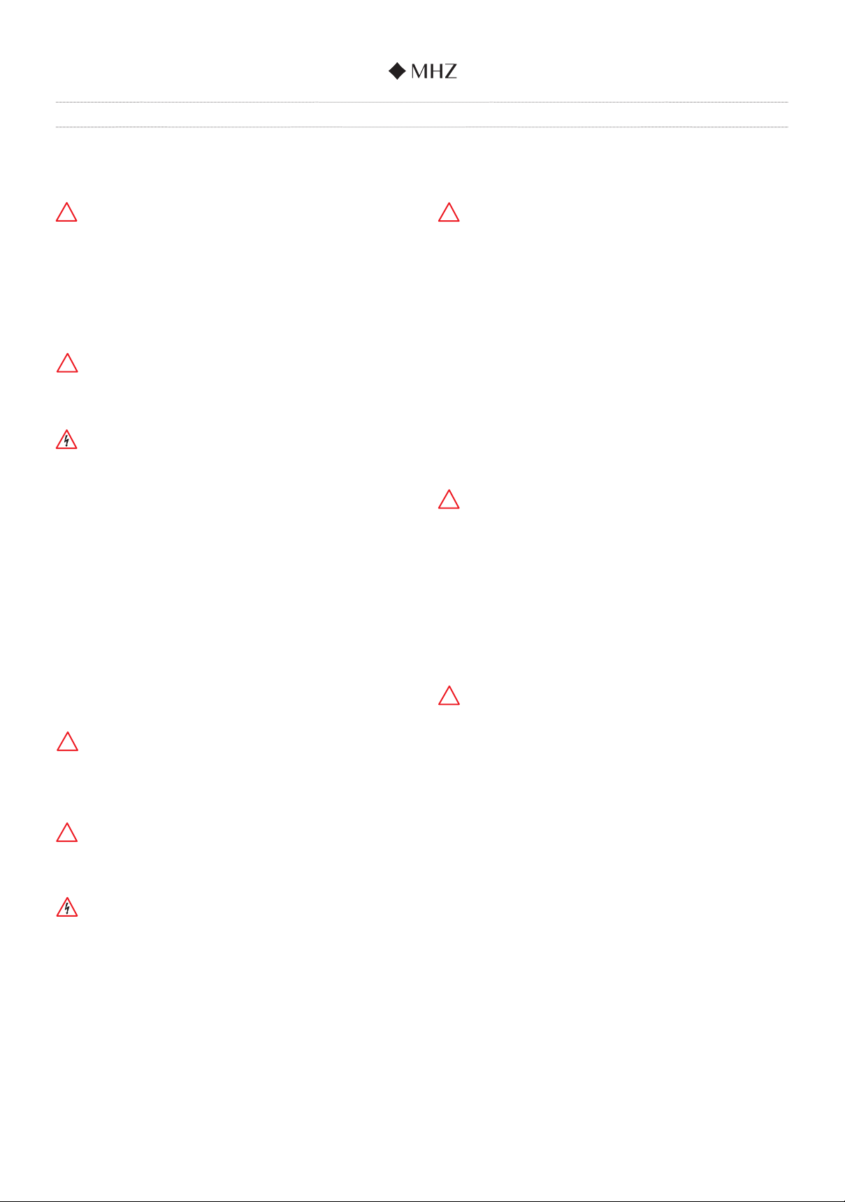
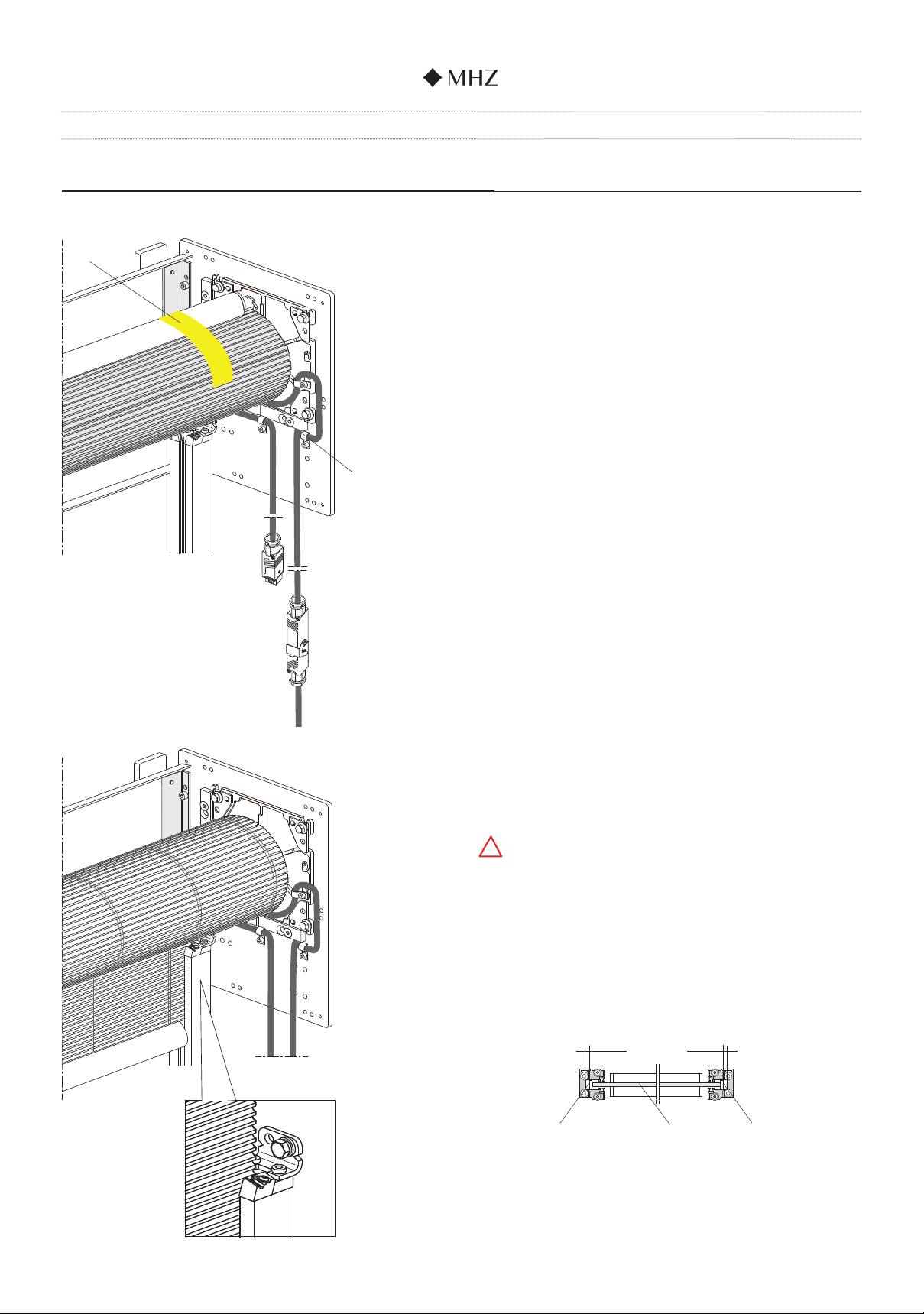
1. Sword-shaped bracket
2. Side plate
3. Guide rail 30x34
4. Wall bracket
5. Metal blind
6. Deection tube
7. Drop bar with guide slider
8. Cover
9. End cover
10. Hirschmann plug coupling
with holde
7
98
2
34
56
1
10
Page 8 Subject to technical changes I Edition 03.2022
Installation instructions for metal blind s_enn SN 72/1, SN 72/2
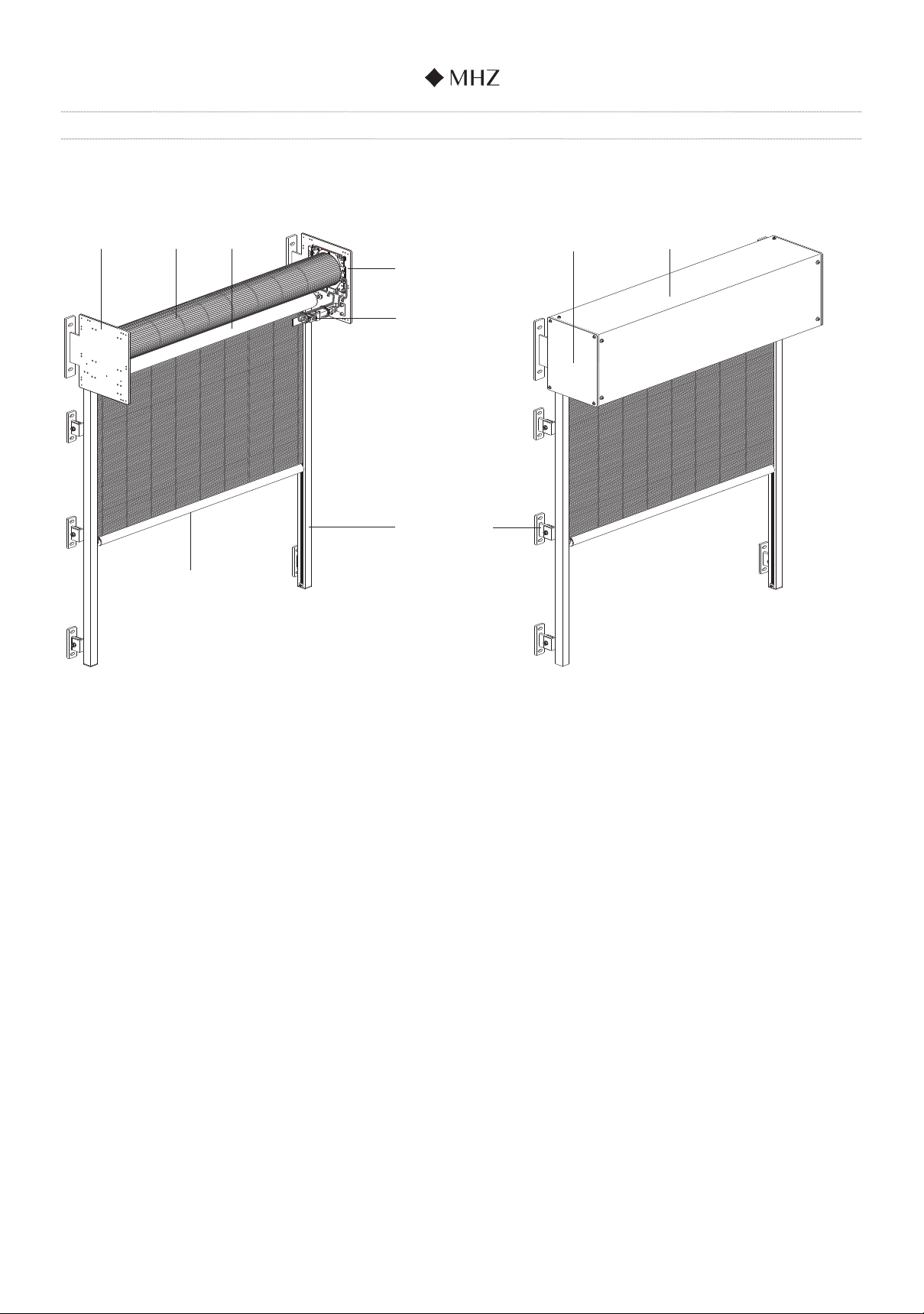
Technical data
Unit height max. 3000 mm
Unit height max. 4500 mm
Unit width:
From 650mm to 2700mm
Unit height:
From 650mm to 3000mm
Cover:
Width: 227mm
Height: 285mm
Unit width:
From 650mm to 2700mm
Unit height:
From 3001mm to 4500mm
Cover:
Width: 267mm
Height: 330mm
SN 72/1 SN 72/2
Unit width Unit width
Grid width Grid width
Light measurement between
the sword holders
Light measurement between
the sword holders
Unit width Unit width
Grid width Grid width
Light measurement between
the sword holders
Light measurement between
the sword holders
Installation instructions for metal blind s_enn SN 72/1, SN 72/2
Page 9 Subject to technical changes I Edition 03.2022
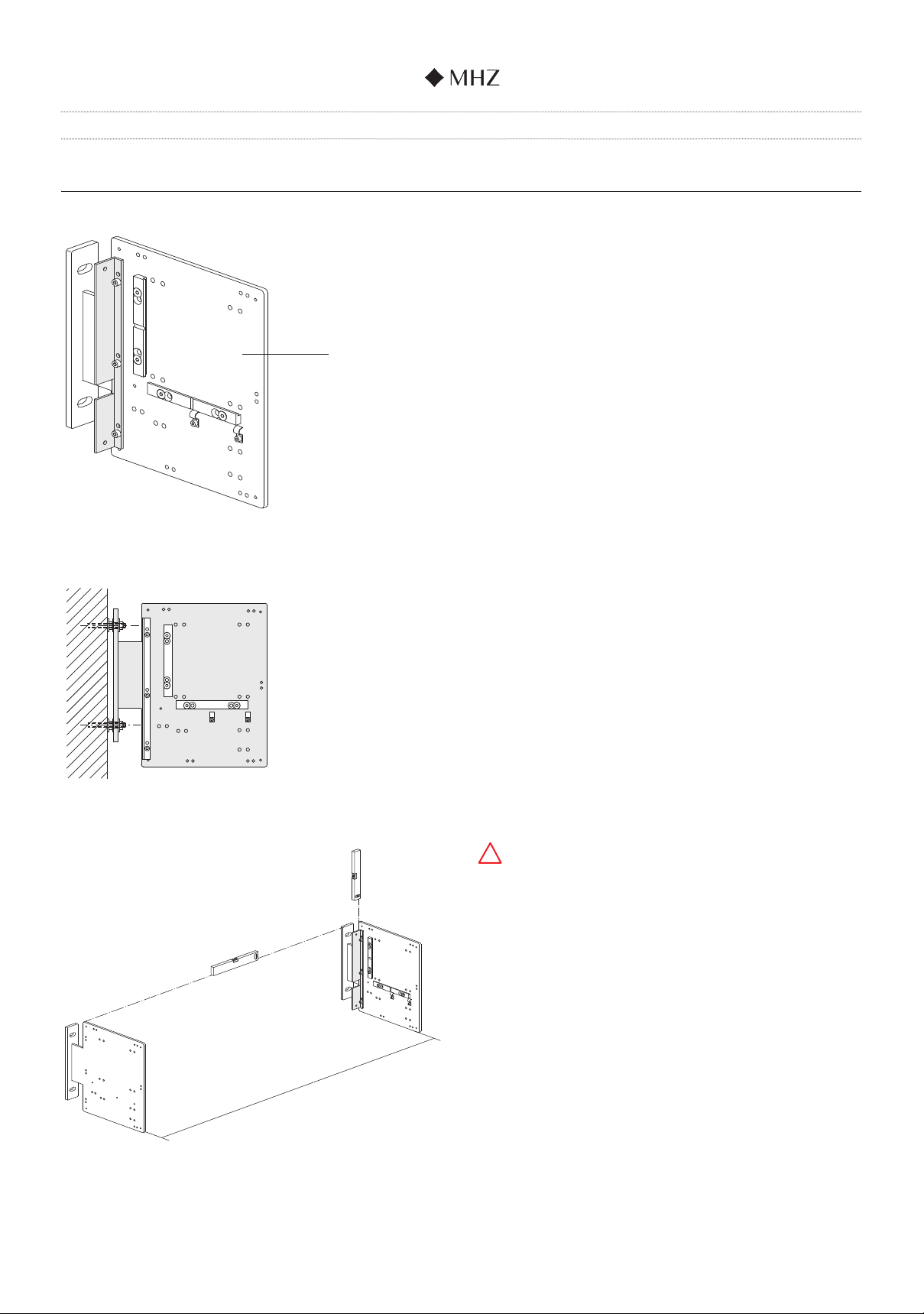
1. Installation of sword-shaped bracket
Position the sword-shaped brackets (1).
Installation example uses on-site threaded bolts.
The metal blind is supplied without ttings.
The sword-shaped brackets must be exactly aligned
vertically and horizontally.
Permissible dimensional tolerance for the clear unit width
between the sword-shaped brackets: +/-2mm
Clear system width
!
1

Page 10 Subject to technical changes I Edition 03.2022
Installation instructions for metal blind s_enn SN 72/1, SN 72/2
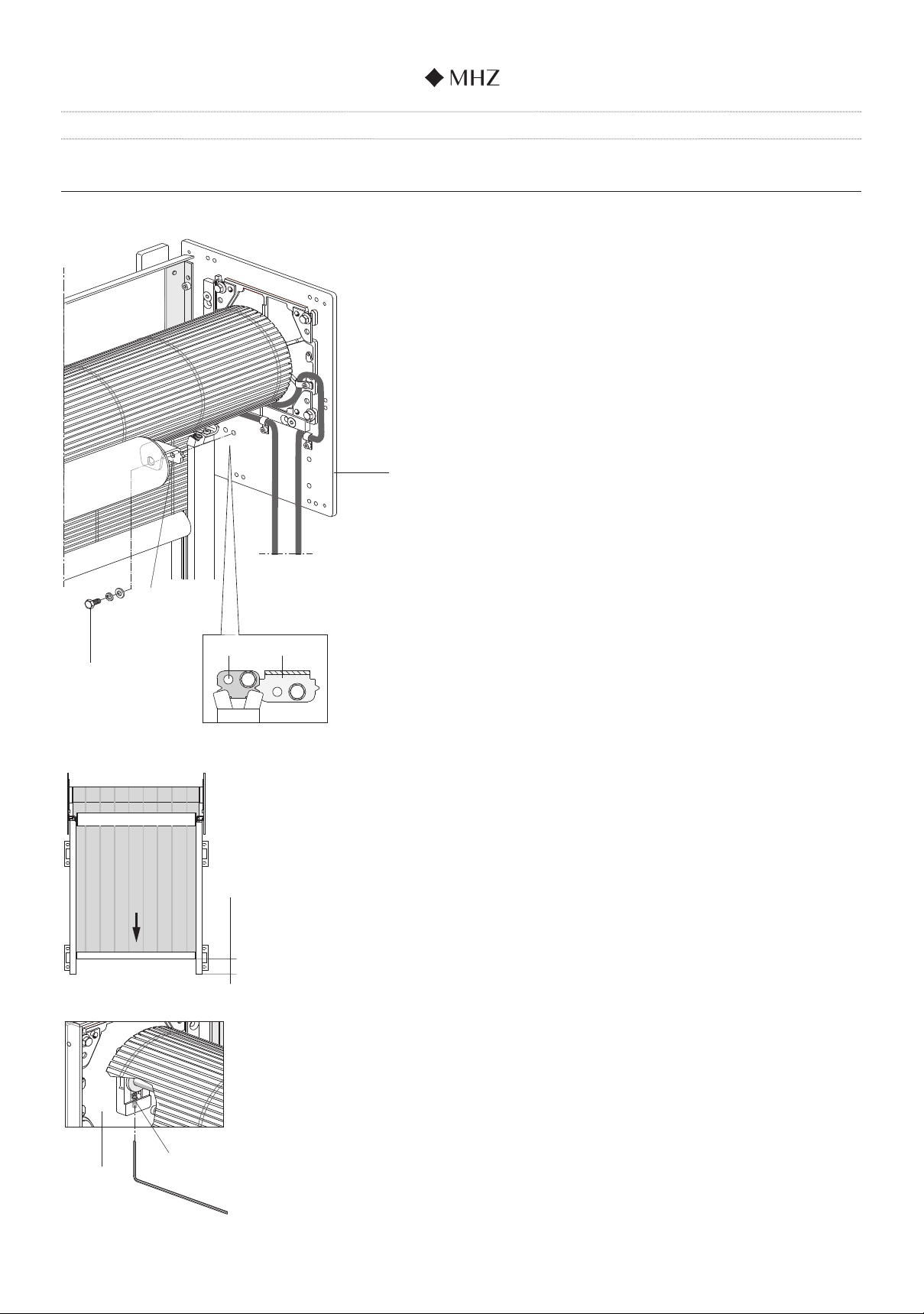
2. Installation of rear cover
Before installing the rear cover (12), you must push the on-
site cable through the cable grommet.
Then push the cable grommet (13) and cable into the recess
in the cover (see detail drawing).
Install the cover and then connect the Stak 3 Hirschmann
coupling. Cable length approx. 40cm.
From the outside, fasten the rear cover (12) to the saddle
at the back (11) of the left and right sword-shaped bracket
(1) with 2 x M5x8 hex bolts and ø5.3 U-washers (14) in each
case.
approx. 40 cm
11
12
1
1412 11
13

Installation instructions for metal blind s_enn SN 72/1, SN 72/2
Page 11Subject to technical changes I Edition 03.2022
max. 1500 mm
X
max. 1500 mm
3. Installation of guide rail 30x34 on sword-shaped bracket
The wall brackets must be pre-mounted prior to installation
of the guide rail 30x34 (3) on the sword-shaped bracket.
Use an M6x25 threaded pin, ø6.4 U-washer and M6 hexagon
nut (15) to bolt the wall brackets (4) to the M6 square nuts
(16) already located in the guide rail (see detail drawing).
Pay attention to measurement X and the distance be-
tween the wall brackets (see also the table).
Measurement X = max. 150mm
Secure the cable in the cable clamp pre-mounted on the
side plate.
Once completed, the guide rails 30x34 (3) are fastened
to the sword-shaped brackets using 1 x M6x12 hex bolt,
ø6.4 U-washer and ø6 spring washer (17) inserted through
the drill holes on the mounting bracket (18) in each case.
The guide rails must be exactly aligned vertically and
parallel to one another
15
3
4
16
!
17
18
Unit height Number of wall brackets
per guide rail
Up to 3000 mm 2
From 3001 - 4500 mm 3
Cable clamp
Clear guide rail dimension =
system width - 74 mm
Permissible dimensional deviation
+/ - 2 mm
3
!

Page 12 Subject to technical changes I Edition 03.2022
Installation instructions for metal blind s_enn SN 72/1, SN 72/2
4. Installation of side plates with blind tube
Push the side plates (2) with blind tube (19) from the front
into the grooves of the support bars (20).
Motor installed on right
Check whether the installed position of the side plates with
blind tube is correct:
- At the side plates, the slots open at the top must
point upwards (see detail drawing)
- The motor cable outlet must point vertically
downwards
Motor installed on left
Check whether the installed position of the side plates with
blind tube is correct:
- At the side plates, the slots open at the top must
point upwards (see detail drawing)
- The motor cable outlet must point vertically
downwards
2
19
20
Illustration
without blind
Illustration
without blind

Installation instructions for metal blind s_enn SN 72/1, SN 72/2
Page 13Subject to technical changes I Edition 03.2022
21 1
150
150
210
210
150x150 side plate Up to 3000mm unit height
210x210 side plate From 3001mm unit height
upwards
INFORMATION: The procedure for installation of the
210x210mm side plates (with stailess-
steel adapter plates) is identical to the
150x150mm side plates shown in the
instructions
Next, x each of the side plates to the sword-shaped
brackets (1) using 4 x M6 hex bolts (21).
150x150 side plate: M6x12 hex bolts
210x210 side plate: M6x10* hex bolts
*The bolts used to install the 210x210 side plates need to be
shorter, otherwise they will collide with the end cover.
Page 14 Subject to technical changes I Edition 03.2022
Installation instructions for metal blind s_enn SN 72/1, SN 72/2
5. Procedure for blind
Fasten the motor cable in the second cable clamp pre-
mounted on the side plate to avoid a stripe on the blind.
Connect the adjustment cable.
Use the adjustment cable to move the blind into a position
where the drop bar is at around 45° at the back and cannot
fall forwards and down when the adhesive tapes (22) are
removed.
Carefully remove the adhesive tapes (22).
Slowly insert the blind into the guide rail on the left
and right (approx. 10cm).
!When it is being inserted, make sure the blind does
not move to either side. It must be inserted into the guide
rails in a central position.
22
Cable clamp
Insertion
groove,
drop bar
adapter
Insertion
groove,
drop bar
adapter
Blind with
drop bar
5 mm 5 mm
Installation instructions for metal blind s_enn SN 72/1, SN 72/2
Page 15 Subject to technical changes I Edition 03.2022
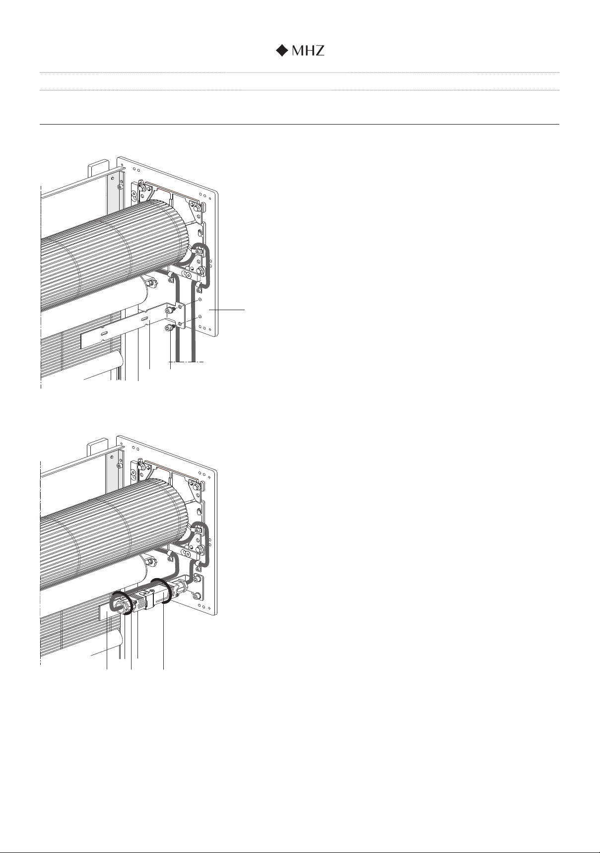
6. Installation of deection tube
Position each mounting bracket for the deection tube
assembly (23) on the sword-shaped bracket (1) using 1 x
M6x12 hex bolt, ø6 spring washer and ø6.4 U-washer (17).
Make sure that the lateral tip of the mounting bracket for the
deection tube (23) snaps into the recess in the mounting
bracket for the guide rail (18) (see detail drawing).
Extend the blind until approx. 100mm from the end of the
guide rail.
Check that the drop bar is aligned centrally to the unit when
extended.
Adjust as necessary using the M6x30 threaded pin (25) locat-
ed in the end position side plate (24).
23
2318
17
1
ca. 100 mm
Allen key size 3
24
25

Page 16 Subject to technical changes I Edition 03.2022
Installation instructions for metal blind s_enn SN 72/1, SN 72/2
7. End position adjustment
Do not apply torque when adjusting the top and bottom end
positions
Please follow the programming procedure in full and in the
order stated here.
nMove the blind and the installation cable into a central
position.
nPress the UP pand DOWN buttons qsimultaneously to
set the drive to its factory setting.
The motor signals that this has happened by initiating an
UP/DOWN movement.
nPress the UP button p: the drive moves approx. 20–50cm,
stops briey, then continues to move.
Move it to just before the end position you want.
You can use the UP/DOWN buttons pqto make any
corrections.
From the specied end position, press the DOWN button
quntil the drive stops.
The top end position is set.
nPress the DOWN button q: the drive moves
approx. 20–50cm, stops briey, then continues to move.
Move it to just before the bottom end position (bottom
edge of the drop bar approx. 15mm above the piping
clip).
You can use the UP/DOWN buttons pqto make any
corrections.
From the specied end position, press the UP button p
until the drive stops.
The bottom end position is now set.
nThe end position adjustment is hereby complete.
The adjustment mode ends after the two end positions
have been set.
nSecond trial run
nDoes the blind move and wind without any problems?
Please check!
nRaise/retract the blind.
Note:
You can reprogram the end positions by repeating points 1
and 2 to restore the motor to its factory setting
10 mm
15 mm
Top end position
Bottom end position
Shown without deection tube
Installation instructions for metal blind s_enn SN 72/1, SN 72/2
Page 17Subject to technical changes I Edition 03.2022
Fasten the plug coupling holder (26) to the sword-shaped
bracket (1) with 2 x M6x10 cylinder screws and ø6.4 U-wash-
ers (27).
Next, t the Hirschmann plug coupling (28) together
and fasten it to the plug coupling holder (26) using
2 x cable ties (29).
2829
26 27
8. Installation of plug coupling holder
26
1

Page 18 Subject to technical changes I Edition 03.2022
Installation instructions for metal blind s_enn SN 72/1, SN 72/2
9. Installation of front cover
The front saddle for fastening the cover must be installed
prior to installation of the front cover.
Attach the front saddle (30) to each sword-shaped
bracket using 5 x M5x8 cylinder screws (31).
Screw the front cover (32) to the left and right front saddle
using 4 x M5x8 cylinder screws and ø5.3 U-washers (33).
Finally, fasten an end cover (9) to the left and right of the
sword-shaped bracket using 4 x M4x6 cylinder screws and
ø4.3 U-washers (34).
31
34
33
32
9
30
Installation instructions for metal blind s_enn SN 72/1, SN 72/2
Page 19 Subject to technical changes I Edition 03.2022
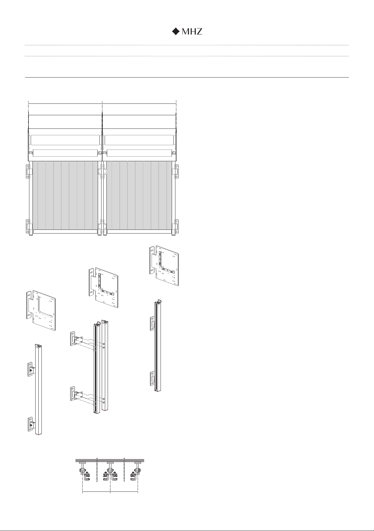
10. Multi-unit systems
The procedure for the installation of multi-unit systems is
essentially identical to the installation of a single-unit system.
When pre-assembling the wall brackets on the guide rails,
the wall brackets for the outer guide rails (3a) are mounted
singly (4a) and the wall brackets for the inner or adjacent
guide rails (3b) are mounted in double (4b).
Unit width
Unit width
Grid width
Grid width
3a
3a
3b3b
4b
4a
4a
Grid
width
Grid
width

Page 20 Subject to technical changes I Edition 03.2022
Installation instructions for metal blind s_enn SN 72/1, SN 72/2
All further installation steps are performed in the same way
as for a single-unit system.
Care must be taken when installing the mounting brackets
for the guide rail and deection tube on the sword-shaped
bracket in the middle to ensure that the fastening screws on
the left and right are mounted offset to each other (see detail
drawing).
If the holders for the plug couplings are positioned centrally
on the sword-shaped bracket as a mirror image (“head to
head” motor arrangement), they must be installed offset to
one another.
Sword-shaped bracket,
central
Top view
Installation
of guide rail bracket,
right
Installation
of deection tube
bracket,
right
Installation
of guide rail bracket,
left
Installation
of deection tube
bracket,
left
Installation
of plug coupling holder,
right
Installation
of plug coupling holder,
left
This manual suits for next models
1
Other MHZ Window Blind manuals


Popular Window Blind manuals by other brands

Draper
Draper FlexShade INSTRUCTIONS INSTALLATION & OPERATION

Norman
Norman LightGuard 360 N301124-G System Installation Instructions

Hella
Hella TOP MINI plus screen Installation instructions and instructions for use

3 Day Blinds
3 Day Blinds 2 Getting started

Blinds Direct
Blinds Direct FAUX WOOD VENETIANS Fitting instructions

Wizard
Wizard SmartScreen manual


LEHA
LEHA KKRO-L Installation and instruction manual

IKEA
IKEA KADRILJ 140 manual

flair21
flair21 VERTICAL WRAP installation instructions

Guthrie Douglas
Guthrie Douglas TESS 140 installation manual

Style selections
Style selections 70816 installation instructions

Outbound
Outbound RA Series installation manual