ENGLISH DEUTSCH ESPAÑOL
9
COD.103202 Rev.4
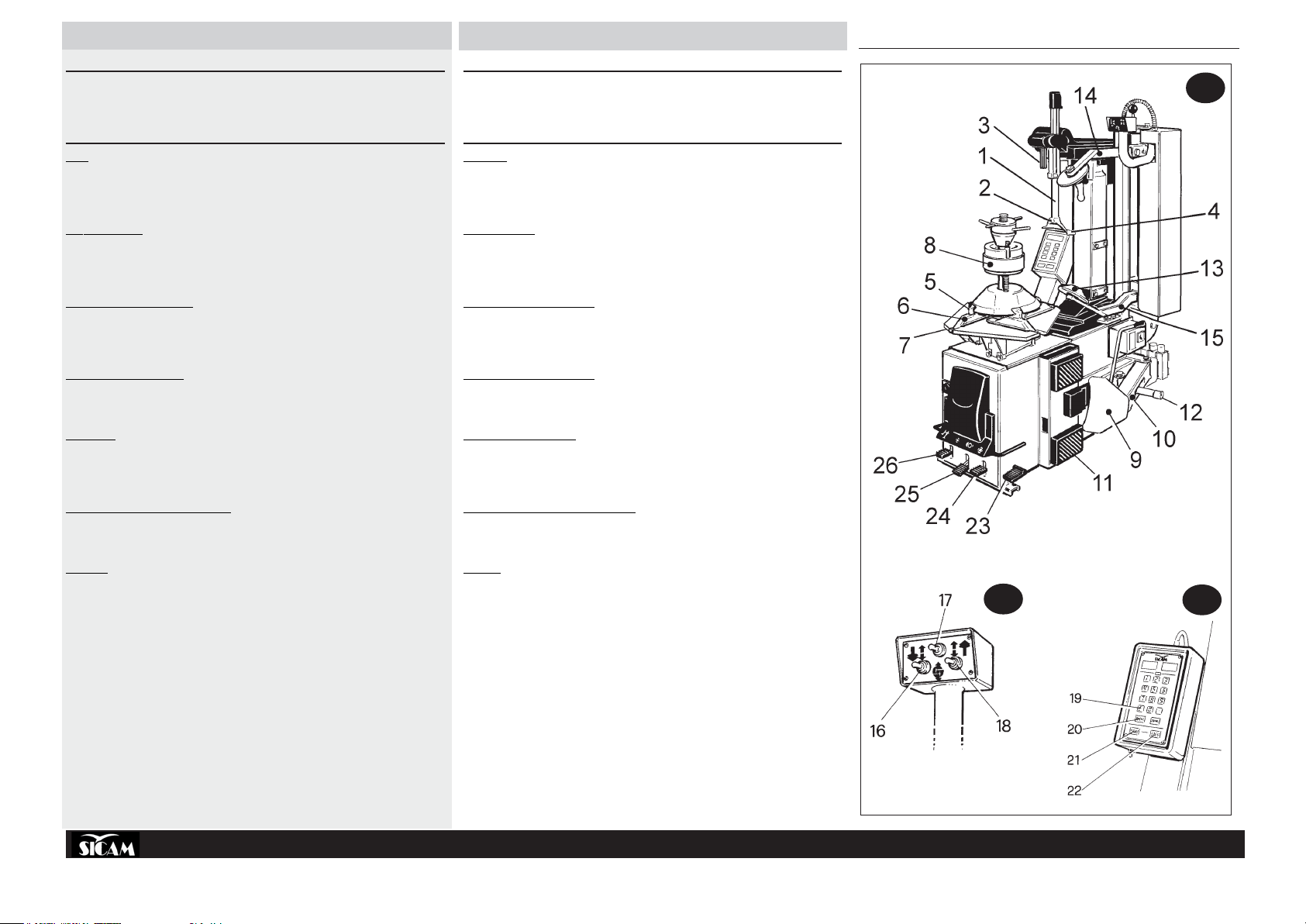
COMPONENT PARTS
BEAD-BREAKERS
HYDRAULIC ROLLER BEAD-BREAKER (Fig. 2)
The “combined” version is equipped with hydraulic roller bead-breaker for the safe bead-breaking of
tyresmountedon alloyorpainted rims.Characteristics:
»Nylon rollers (fig.1-13)mountedonfixedarmsoperatinginperfectsymmetrytohelptheoperator
whenpreparingbead-breaking.
» The symmetrical action of the teflon rollers combined with the movement of the chuck allows opti-
mumefficiencywhen bead-breakingwithoutcausing any damagetotherim or tyre.
»The upper roller arm (14) can be disengaged by extracting the fixing pin to facilitate mounting
operations.
» The lower roller arm (15), as well as functioning as a bead-breaker, is particularly useful for pre-
ventingtyresfrom beading backinduring demounting andforhelpingthe extractionprocess.
» The control panel governsallhydraulicmovement (see the controls section - fig. 7 on pg. 10).
PNEUMATIC BEAD-BREAKER (Fig. 3)
Thepneumatic bead-breakeristhetraditionaldeviceforbead-breaking tyresfromrims (fig.3)and itis
composedof:
»Bead-breaking arm (10) driven pneumatically by a double action cylinder
»Bead-breaking plate (9)forbead-breakingtyres
»Anti-abrasive supports (11)forsupportingtherim during bead-breaking
»Threeposition devicewhichallowsthewidthofopeningofthebead-breakerplatetobeeasilyand
quicklyadjusted (12).
MOVABLE SELF-CENTRING CHUCK (Fig. 4)
The backwards and forwards movement of the chuck (fig. 4) (Sicam patent) is fundamental for bead-
breakingtyres, regardlessofthe rimformat.
Thechuckispoweredpneumaticallybytwocylindersandiscomposedof:
»4 sliding tracks (6) with locking jaws (5) for locking the rim internally or externally
»Rim anchoring device (8) which locks onto the chuck and is specially designed for working on
specialrimsandtyres
»Chuck plate (7)forrotatingtheriminbothdirectionswithoutunlockingit.
Thecasingdimensionsallowworkonwheelsofupto1180 mm.
TILTING COLUMN (fig.5)
Thetiltingcolumn hastwo (vertical)operatingpositions andcarries thepartsnecessaryfordemount-
ingand (re-mounting)tyres:
»Sliding arm (1) for the horizontal positioning of the head
»Grip (3) for horizontal locking of the sliding arm and vertical “tyre” locking of the head and for
simultaneouslysettingan automaticgapof 3mm(adjustable) from therimflange.
» The tool head (2) for removing (and re-mounting) tyres from rims with the help of the bead-lifting
lever(see accessoriessupplied).
» Thesliding roller(4), insertedinside thehead, avoidsany frictionbetween thehead andrim during
tyremounting anddemounting.
»Tongue:Aspecial“protectiontongue”designedfor usewith aluminiumrims (seesection“Accesso-
rieson request”).
EINZELTEILE
WULSTABDRÜCKER
HYDRAULISCHER ROLLEN-WULSTABDRÜCKER (Abb. 2)
DieAusführung“COMBINED”verfügtübereinenhydraulischenRollenwulstabdrücker,mitdemdieReifen
sichervonlegierten oderlackiertenFelgen abgewulstet werdenkönnen.Seine Merkmalesind:
»Nylonrollen (Abb.1-13), auf starren Armen montiert, operieren vollkommen symmetrisch und
erleichternso fürdenBedienerdieeinzelnenAbdrückvorbereitungen.
» Die symmetrische Funktion der Teflonrullen erlaubt zusammen mit der Bewegung des
Selbstzentrierers die optimale Leistungsfähigkeit während des Wulstab-drückens, ohne dabei auf
irgendeineWeiseweder den FelgennochdemReifen zu beschädigen.
» Der obere Rollenträgerarm (14) kanndurchHeraus-ziehendesBefestigungszapfensabgeboben
werdenund erleichtertdamit dieMontageoperationen.
» DeruntereRollenträgerarm(15)dientaußerzumallgemeinenWulstabdrückendazu,dasWiederein-
wulstendesReifens zu vermeidenunddasHeraus-ziehen zuerleichtern.
» Der Kommandoknüppel setzt alle hydraulischen Bewe-gungen in Gang (siehe Abschnitt
Kommandos,Abb.7auf Seite 10).
PNEUMATISCHER WULSTABDRÜCKER (Abb. 3)
DerpneumatischeWulstabdrückeristeinetraditionelleVorrichtung zum Wulstabdrücken des Reifens
vomFelgen(Abb.3)undbesteht aus:
» Abdrückkralle(10),die von einem DoppelzylinderinGanggesetzt wird;
» Klaue(9)fürdas Wulstabdrücken desReifens
» KratzsichereHalterungen(11)fürdasAufsetzendes FelgenswährenddesWulstabdrückens
» Dreifach einstellbare Vorrichtung, mit der die Öffnungsweite der Abdrückklaue höchst einfach
eingestelltwerden kann(12).
BEWEGLICHER SELBSTZENTRIERER (Abb. 4)
Die Vorwärts- und Rückwärtsbewegung des Selbstzen-trierers (Abb. 4) (SICAM-Patent) ist
ausschlaggebendfür dasWulstabdrückendesReifensunabhängig vonderFelgenform.
DerSelbstzentriererwirdvon zwei Zylindern pneumatisch inGanggesetztundbesteht aus
»4beweglichenSchienen (6)mitBlockierungsrillen(5)fürdie Innen-undAußenblockierungdes
Reifen-felgens;
»Verankerungsvorrichtung des Felgens (8), auf dem Selbstzentrierer festgemacht, wurde
zweckmäßigfürdasArbeiten mit Spezialfelgenund-reifen entworfenundhergestellt
»Selbstzentriererplatte(7)zur DrehungdesFelgens inbeideRichtungen,ohne ihnzuentblocken.
DieMaßedes Gehäuses sind fürReifenbiszu maximal 1180 mmDurchmesserbestimmt.
KIPPBARE TRAGSÄULE (Abb.5)
DiekippbareTragsäulezweifacheBetriebseinstellung(Senkrechtstellung),trägtdiefürdasAbmontieren
desReifensvom Felgen(undfür dieNeumontage)erforderlichen Einzelteile.
»Schwenkbarer Laufarm (1)für die Waagrechtstellungdes Drehkopfs;
»Drehknopf (3) für die pneumatische Blockierung des Schiebearmes und der Drehkopfgruppe in
waagrechterundsenkrechterStellungundzurgleichzeitigenautomatischenEinstellungdesAbstands
(3mm, regulierbar)vom Felgenrand;
»Drehkopf (2) für die Ab- undAufmontage des Reifens vom und auf den Reifenfelgen mit Hilfe der
Wulstabdrückerstange(sieheStandardzubehör).
» Die Gleitrolle (4), im Innern des Drehkopfs eingebaut, um jegliche Reibung zwischen Felgen und
DrehkopfwährenddesAb- undAufmontierensdesReifenszu vermeiden.
»Keil:FürAlluminiumfelgenistein“Spezial-Schutzkeil”vorgesehen (sieheSonderzubehör)
PIEZAS COMPONENTES
DESTALONADORES
DESTALONADOR HIDRAULICO DE RODILLOS (fig.2)
La versión “combined” está equipada con un destalonador hidráulico de rodillos para destalonar con
seguridadlosneumáticosmontadossobrellantasdealeaciónobarnizadas.Lascaracterísticas sonlas
siguientes:
» Los Rodillos de nylon (fig.1-13) montados sobre brazos fijos, actúan de manera simétrica para
facilitaral operadordurantelasoperacionesdedestalonamiento.
» Lafunciónsimétricadelosrodillosdeteflón,acordadaconelmovimientodelautocentrado,permite
realizar la máxima y óptima operatividad durante el destalonamiento sin dañar ni la llanta ni el
neumático.
» Elbrazo portarodillo superior(14), sacandoelperno sujetador, tienelaposibilidad desersoltado
parafacilitar lasoperacionesde montaje.
» El brazo portarodillo inferior (15) además de desarrollar la función general de destalonamiento,
esmuyútil para evitar elretalonamientodelneumáticoy para facilitar supropiaextracción.
» Elcuadro de control activatodoslosmovimientoshidráulicos(véaselaseccióndelosmandosy
véase Fig. 7 en pág. 10).
DESTALONADOR NEUMATICO (fig.3)
ElDestalonador neumáticoeseldispositivotradicionalparadestalonarelneumáticodelallanta(fig.3)
eincluye:
»Brazo Destalonador (10)accionadoneumáticamenteporuncilindro de doble efecto.
»Paleta(9)paraeldestalonamiento delneumático.
»Apoyos antiabrasivos (11) paraapoyarlallantadurantela fase de destalonamiento.
»Dispositivo de 3 posiciones que consiente de variar la abertura de la paleta destalonadora con
granfacilidady rapidez (12).
AUTOCENTRADO MOVIL (fig.4)
Elmovimientohacia delante y hacia atrás delAutocentrado (Fig. 4) (patente Sicam) es indispensable
pararealizareldestalonamiento delneumático, independentementede laconformacióndelallanta.El
Autocentrado es el dispositivo que se acciona neumáticamente gracias a dos cilindros y se compone
de:
»4recorridos móviles (6)concuñas debloqueo (5)parael bloqueointeriory exteriordela llanta.
»Undispositivo de anclaje de la llanta (8), bloqueado sobre el autocentrado ideado adrede y
realizadoparaobrar sobrellantasy neumáticosespeciales.
»Unplato autocentrado (7) para girar la llanta en los dos sentidos sin desbloquearla.
Las dimensiones de la caja consienten de actuar sobre ruedas con un diámetro máximo de 1180
mm.
COLUMNA VOLCABLE (fig.5)
LaColumna Volcableutilizableen2posiciones(verticales)soportaloscomponentesnecesariospara
desmontarel neumáticodela llanta(yparamontarlonuevamente):
» El Brazo corredizo (1) para la colocación horizontal de la Torre;
» ElBotón de bloqueoneumático(3)permite obtener con unaúnicaoperaciónseala distancia de3
mm(ajustables)desdeelbordedelallanta,seaelbloqueohorizontaldelbrazodeslizanteyvertical
delcuerpodelatorre.
» LaTorre (2) para quitar con el auxilio de la palanca levanta-talones (vea accesorios de equipo) el
neumáticode lallanta(yparamontarlo nuevamente).
» ElRodillodedeslizamiento(4)introducidoenlaranuradelaTorre,permiteactuarsobreelneumático
evitandoelfrotamiento entre lallantayla torre durantelasoperacionesde montaje ydesmontaje.
»Lengüeta:Paralas llantas dealuminioestáprevista una“LengüetaProtectora”especial (véase la
seccióntitulada “Accesoriosdeequipo”).