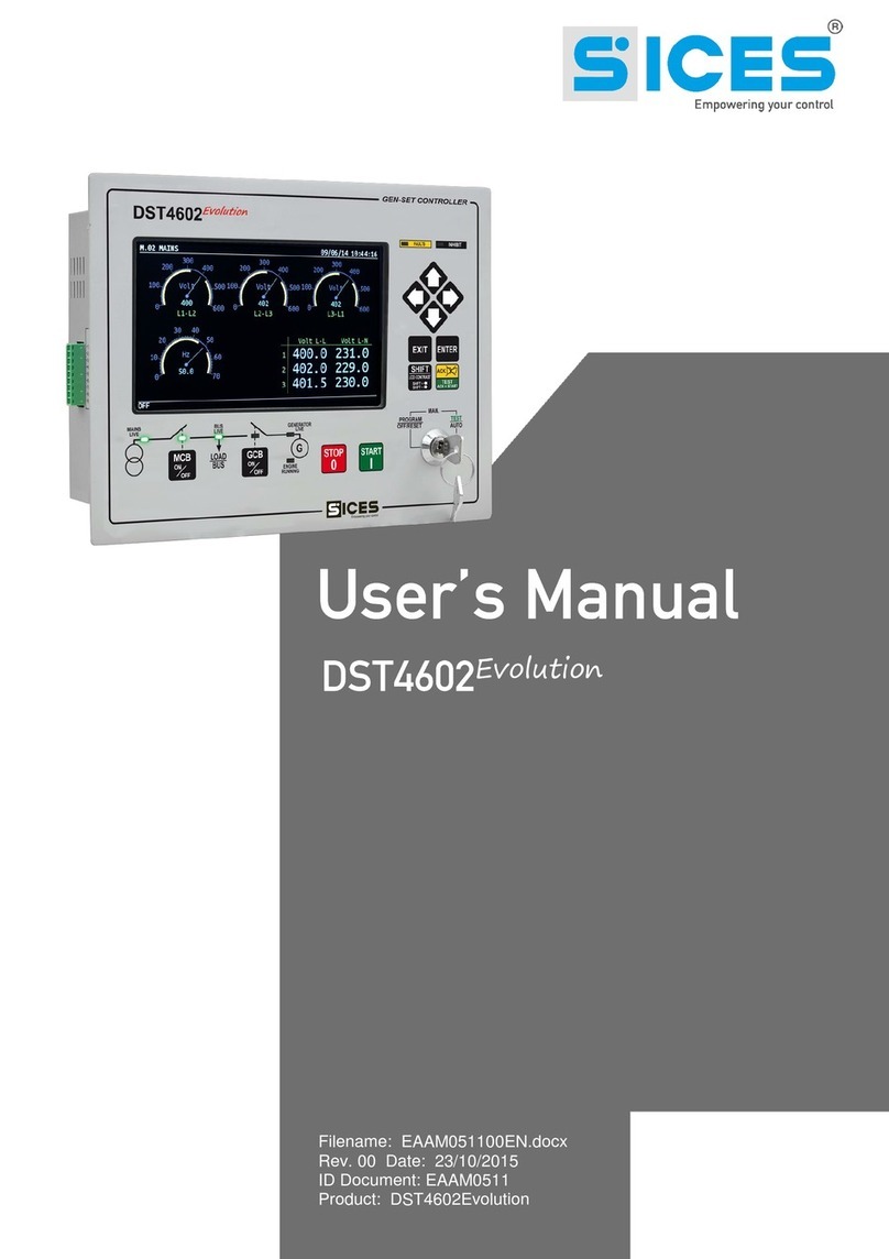
Sices RN200 User manual

File name: EAAM072500EN.docx
Rev. 00 Date: 03/08/2020
ID Document: EAAM72500
Product: RN200

ii RN200 user manual
1Safety information........................................................................................................1
2Maintenance and cleaning...........................................................................................1
3Information concerning disposal................................................................................1
4General info...................................................................................................................1
5Definitions.....................................................................................................................1
6Main functions..............................................................................................................3
6.1 Front panel ...........................................................................................................3
6.2 Buttons .................................................................................................................3
6.3 Indicators..............................................................................................................6
6.4 Multifunctional display...........................................................................................8
6.4.1 Display lighting...............................................................................................8
6.4.2 Contrast adjustment .......................................................................................8
6.4.3 Colours scheme .............................................................................................8
6.4.4 Mode navigation.............................................................................................8
6.4.5 Structure of display areas...............................................................................9
6.4.6 Upper status bar.............................................................................................9
6.5 Display modes....................................................................................................11
6.5.1 Programming (P.XX) ....................................................................................11
6.5.2 PLC (L.XX)...................................................................................................13
6.5.3 Status information (S.XX).............................................................................14
6.5.4 Electrical measures (M.XX)..........................................................................19
6.5.5 Renewable sources (R.XX)..........................................................................21
6.5.6 Measurements from Can Bus PMCB (B.XX)................................................23
6.5.7 History logs (H.XX).......................................................................................25
7Operating principles...................................................................................................26
7.1 Connection to inverters.......................................................................................26
7.2 Operation modes................................................................................................26
7.3 Manual commands .............................................................................................27
7.3.1 RNCB circuit breaker....................................................................................27
7.3.2 Inverter.........................................................................................................28
7.4 Most important parameters.................................................................................29
7.4.1 Minimum power for generators.....................................................................29
7.4.2 Spinning reserve for generators...................................................................29
8Special setting............................................................................................................31
8.1 Selecting the language.......................................................................................31
8.2 Date/time setting.................................................................................................31

RN200 user manual 1
The manual must be kept with care and must always be available for quick reference.
The manual must be carefully read and understood in each of its paragraphs by the
peoplewho must use the device and who will carry out normal operations and periodic
maintenance.
If the manual is lost or damaged, request a copy from the installer or manufacturer,
providing the model, device code, serial number and year of construction.
Many accidents are caused by insufficientknowledge and non-application of the safetyrules,
which must be put into practice during operation and/or maintenance operations.
To avoid accidents, beforecarrying out any operation and/or maintenance, read, understand
and follow the precautions and warnings contained in this manual.
The following indications have been used to identify the safety messages included in this
manual:
WARNING! This indication is used in safety messages for dangers which, if not
avoided, can cause malfunctions or damage to property or persons.
INFORMATION! This term indicates that the message provides information useful
for carrying out the operation in progress or for clarifying or specifying procedures.
Maintenance of this device must be carried out by qualified personnel, in compliance with
current regulations, in order to avoid damage to people or things.
The front panel can be cleaned only with a soft cloth, do not use abrasive products, liquid
detergents or solvents.
INFORMATION! Disposal of old electrical and electronic equipment (applicable in
European countries that have adopted separate waste collection systems).
Products bearing the symbol ofa crossed-out wheeled bin cannot be disposed of with normal
household waste. Old electrical and electronic products must be recycled at a special facility
capable of treating these products and disposing of their components. To find out where and
how to deliver these products to the place closest to you, contact the appropriate municipal
office. Proper recycling and disposal helps to preservenature and prevent harmful effects on
health and the environment.
This manual describes the RN200 controller.
BLOCK: it is used to indicate an anomaly that makes it impossible to use renewable sources,
and causes the inverters to automatically switch off.
WARNING: it is used to indicate an anomaly that requires operator intervention, but which
does not prevent the use of renewable sources.
MAINS: public electricity provider.

2RN200 user manual
RENEWABLE SOURCES:identifies the set of real sources (photovoltaic, wind etc.) and the
inverters that manage them.
GENERATORS: refers to synchronous generators, consisting of a combustion engine (diesel,
gas, biogas etc.) and an alternator.
COMMON BARS: power line consisting of one or more generating sets and renewable
sources.
MCB: circuit breaker connecting the mains to the loads.
GCB: circuit breaker connecting one generator to the common bars.
RNCB: circuit breaker that connects a group of renewable sources to the common bars.
MGCB: circuit breaker that connects the common bars to the loads.
CANBUS: communication interface used by all SICES controllers for the exchange of
information between them.
ISLAND: we mean a type of plant where the loads are powered by generators and renewable
sources, but not by the mains.
PARALLEL TO THE MAINS: means a type of plant where the loads are powered by the
mains, and possibly also (simultaneously) by the generators and renewable sources.

RN200 user manual 3
6.1
6.2
Button
Function
MODE UP
MODE
DOWN
OFF/RESET
PROGRAM
The inverters for the renewable sources are stopped. The RNCB circuit
breaker is open. Parameters can be changed.
MAN
(Manual)
The controller is ready for manual use of renewable sources.
Press the START button to start the inverters.
Press the STOP button to stop the inverters.
Press the RNCB button to open/close the RNCB circuit breaker.
AUTO
(Automatic)
The controller is ready for the automatic management of the inverters for the
renewable sources, which will be started when the conditions of the system
allow/require it.

4RN200 user manual
Button
Function
ESC/SHIFT
Allows to cancel the modification in progress on a parameter, go back to the
upper menu, and exit programming. If pressed for two seconds from any
menu, it allows to exit programming by storing the position, for a subsequent
return to the same position.
When pressed in any window it provides status information in the top row
(alternating it cyclically).
In the display pages which provide for timed rotation of the information
displayed, it prevents rotation (keeps current information visible).
Pressed together with the button ACK/ENTER:
•Allows you to "accept" any anomalies on the non-volatile memory at
power up.
•Allows to perform a pending firmware update at power up.
•According to the selected page, if pressed for at least 5 seconds it
allows you to reset the counters, reload the default values for the
parameters, delete the historical archives, force the exit from the BUS
OFF mode of the Can Bus etc.
Used in combination with the LEFT or RIGHT button, it allows contrast
adjustment:
•ESC/SHIFT + LEFT: to decrease the contrast (lighten).
•ESC/SHIFT + RIGHT: to increase the contrast (darken).
Pressed together with the button UP and DOWN:
•Allows to change the brightness of the lamps.
•Allows to change the parameters of 10 units at a time
Horizontal navigation buttons:
•They allow to select the previous or next display page.
•When editing a text type parameter, they are used to position the
cursor under the character to be edited.
•In the display pages dedicated to the PLC, they allow to switch the
display of resources between user-defined symbols and predefined
symbols.
•Used in combination with the ESC/SHIFT button, they allow contrast
adjustment:
oESC/SHIFT + LEFT: to decrease the contrast (lighten).
oESC/SHIFT + RIGHT: to increase the contrast (darken).
Vertical navigation buttons:
•They allow to select the previous or next display mode (intended as a
group of pages).
•Pressed together with the ESC/SHIFT button, they allow to change
the brightness of the lamps.
•They allow to scroll through the anomalies if they are not on the
display.
•During the modification of a parameter, they are used to increase /
decrease the value (or the selected character) of a unit (if pressed
with the ESC/SHIFT button, the value is modified by 10 units).
•While viewing the parameter menus or the historical archive, they
allow you to go to the previous/next item.

RN200 user manual 5
Button
Function
ACK/ENTER
When an alarm or a warning occurs, a first press of the button deactivates the
siren. A further press of the button recognizes the presence of anomalies and
automatically removes thewarnings (if the operating conditions have returned
to normal). If kept pressed for 5 seconds, it performs a complete reset of the
anomalies (including alarms).
In the pages that display the board's analogue/digital inputs and outputs, it
allows you to switch the display between logical, physical or function-related
states.
Activates the alarms scrolling mode if they do not fit in the display.
While viewing the parameter menus or the historical archive, it allows to enter
a submenu.
While viewing the parameters, it allows to start and confirm a change
operation.
Pressed together with the button ESC/SHIFT:
•Allows you to "accept" any anomalies on the non-volatile memory at
power up.
•Allows to perform a pending firmware update at power up.
•According to the selected page, if pressed for at least 5 seconds it
allows you to reset the counters, reload the default values for the
parameters, delete the historical archives, force the exit from the BUS
OFF mode of the Can Bus etc.
RNCB
In the "OFF/RESET" and "AUTO" modes, the button is disabled.
In "MAN" it is used to open and/or close the RNCB circuit breaker.
When you want to open the circuit breaker, a single press first involves
transferring the loads from the renewable sources to the generators or to the
mains and then opening it; if you want to open RNCB immediately, press and
hold the button for 1 second.
START
In MAN mode it can be used to control the start-up of the inverters for the
renewable sources. Note: starting of the inverters is only possible if RNCB is
closed and the voltage on the common bars is present and within tolerance.
When the controller is turned on:
•Holding it together with the STOP button allows access to special
functions.
STOP
In MAN mode it is used to stop the inverters for the renewable sources.
In OFF/RESET mode, it turns on all the lamps in order to check their
efficiency (in this phase, the controller also activates the outputs configured
with the DOF.3153 function, allowing you to also test the lamps on the
panel).
When the controller is turned on:
•Allows to repeat the test of the non-volatile memory if there are
errors.
•Ignores any pending firmware update.
•Holding it together with the START button allows access to special
functions.

6RN200 user manual
6.3
It is possible to change the brightness of the indicators (all together) using parameter P.0496:
the greater the value of the parameter, the greater the brightness of the lamps. The value can
be set between 1 and 10 (default value = 5).
Led off
Led on
Led blinking
Icon
Function
Indicates that the operating mode is OFF/RESET.
Indicates that the PROGRAMMING menu is being accessed.
The controller is in another operating mode.
Indicates that the operating mode is MANUAL.
The controller is in another operating mode.
Indicates that the operating mode is AUTOMATIC.
Flashing 90% on: indicates that the operating mode is REMOTE
START.
The controller is in another operating mode.
Indicates the presence of at least one alarm.
Indicates the presence of at least one warning.
There are no anomalies.
Indicates that at least one external device (inverter) is
communicating correctly with RN200.
Indicates that no external device (inverter) is communicating
correctly with RN200.
Indicates that the Can Bus interface is active, functioning and in
ERROR-ACTIVE mode.
Flashing 25% on: indicates a communication anomaly: the
interface is in ERROR-PASSIVE mode.
Flashing 75% on: indicates a communication anomaly: the
interface is in BUS-OFF mode.
Indicates that the Can Bus interface is disabled.
Indicates that a Modbus slave connection is active (serial ports,
Ethernet or USB).
Indicates that no Modbus slave connection is active (serial
ports, Ethernet or USB).

RN200 user manual 7
Icon
Function
Presence of voltage on the loads.
No voltage on the loads.
The voltages on the common bars are present and within the
tolerance range.
No voltage on the common bars.
Flashing at 50%: in the transients between the two previous
states.
Flashing 25% on: the voltages on the common bars are present
but below the tolerance range.
Flashing 75% on: the voltages on the common bars are present
but above the tolerance range.
The RNCB circuit breaker is open.
The RNCB circuit breaker is closed.
Flashing 25% on: when open with closing command.
Flashing 75% on: when closed in the presence of an opening
command.
All inverters are stopped.
At least one inverter is running.
Flashing 25% on: no inverter running in the presence of a start
command.
Flashing 75% on: at least one inverter running in the presence
of a stop command.

8RN200 user manual
6.4
The backlighting lamp is managed by the controller, which switches it off if no button is pressed
within a configurable time (P.0492). To turn it back on, just press any button (it is advisable to
use the ESC/SHIFT button which, when alone, does not perform any operation). It is possible
to disable automatic shutdown by setting parameter P.0492 to 0.
By using parameter P.0493, it is possible to force the lamp always on when the inverters for
the renewable sources are running.
For a correct view of the display, depending on the ambient temperature conditions, the
contrast adjustment may be necessary.
Press the ESC/SHIFT + ◄ button in sequence to decrease the contrast (lighten), press the
ESC/SHIFT + ► button to increase the contrast (darken).
By factory default, the controller shows information on the display using a blue background
colour. However, this behaviour can be changed using parameter P.0499:
•P.0499 = 0: blue background.
•P.0499 = 1: black background.
•P.0499 = 2: white background.
The colour of the messages depends on the background colour selected and the type of
information displayed.
The display has different viewing modes, each consisting of several pages.
Mode
Description
Page identifier
PROGRAMMING
Programming.
P.XX
PLC
Information on the PLC program.
L.XX
STATES
Status information.
S.XX
MEASURES
Electrical measurements.
M.XX
RENEWABLES
Measurements from the inverters for
the renewable sources.
R.XX
PMCB
Pages related to the Can Bus PMCB
communication interface
B.XX
HISTORY LOGS
Historical archives
H.XX
Generally, the navigation between the modes is done using the ▲ and ▼ buttons. To view the
pages within a mode, use the ◄ and ► buttons. Some modes are organized in menus (P.XX
and H.XX): in these cases, to view the pages, it is necessary to press the ACK/ENTER button
and then the ▲ and ▼ buttons.
In the event that the ▲ and ▼ buttons are to be used to manage specific functions within a
page, the ACK/ENTER buttons are required to activate these functions, the ESC/SHIFT
buttons to deactivate them.

RN200 user manual 9
The upper status bar contains navigation, time and/or some status information.
From left it contains:
•The current mode identifier ("M" in the example ").
•The current page identifier, in the selected mode ("05" in the example ").
•A title ("POWERS" in the example) that briefly describes the content of the page. The
title is translated into the language selected by the operator.
The mode identifier, together with the page identifier ("M.05" in the example) allows to refer
unambiguously to a page.
The title can be replaced with information relating to the status of the system. You can do it in
three ways:
•By holding down the ESC/SHIFT button. The title will be shown again when you
release the button.
•With a double click of the ESC/SHIFT button. The title will be shown again when
selecting a new page or a new display mode.
•By activating bit 6 of parameter P.0495. If there are status messages that contain a
waiting time (countdown), the controller always displays these messages instead of
the title; in case of page change (user manual navigation), the title of the new page
LEGEND:
1 –Status bar
2 –Data area
1
2
M.05 POWERS _
T0kW 1.00i
L1 0kW 1.00i
L2 0kW 1.00i
L3
0
kW
1.00
i

10 RN200 user manual
will be displayed for two seconds and then return to display the status message
requested by the sequence.

RN200 user manual 11
6.5
This mode allows the display and change of the programming parameters.
WARNING! Assigning an incorrect value to one or more parameters can cause
malfunctions, damage to things or injury to people. The parameters must only be
changed by qualified personnel. Parameters may be password protected (see par.
6.5.1.1).
Each parameter (3) is associated with a 4-digit numeric code ("0116" in the example) which
allows to identify itregardless ofthe language used.Thecurrent value of the parameter("400")
is shown in brackets below the description ("Renewables nominal voltage (V)").
The first line below the title bar (2), allows you to identify the current menu by means of a
numeric identifier ("1.4") anda language-dependent description ("Renewable sources"). In this
row a pair of numbers (“3/06”) is displayed on the right. The first number indicates which menu
item is selected, the second indicates how many items are present in the menu.
Pressing ESC/SHIFT button, the first line (1) is temporarily substituted with a status
message.
Use the ▲ and ▼ buttons to select the programming mode (press them until "PROGRAM"
appears on the display). Then press the ACK/ENTER button to access the programming
menus.
After this operation, the controller will show the last parameter or the last menu used by the
operator. If it is not what you want, use:
•The ▲ and ▼ buttons to select a submenu or parameter.
•The ESC/SHIFT button to go back to the upper menu.
•The ACK/ENTER button to enter a submenu.
When the display shows the parameter to be modified, the current value of the parameter is
shown in square brackets, for example "[0400]". If instead it is enclosed in the symbols "<>"
(for example "<400>"), it means that you do not have the rights to modify the parameter. This
may depend on:
•The device is not in OFF/RESET mode. In fact, most of the parameters can only be
changed in this mode.
P.05 PROGRAM _
1.4 Renewable sources ____ _3/06
0116-Renewables nominal voltage (V)
[400]
______________________________________
Access level: manufacturer_
2
3
LEGEND:
1 –Title bar
2 –Current menu
3 –Current parameter
4 –Parameter value
5 –Access level
1
4
5

12 RN200 user manual
•The parameter is protected with a password: to modify the parameter, first enter the
required password in parameter "0000" (see later).
To modify a parameter, press the ACK/ENTER button: the square brackets flash. Use the ▲
and ▼ buttons to change the value and press ACK/ENTER to confirm or ESC/SHIFT to cancel
the change.
To exit the programming menu, press the ESC/SHIFT button several times until you return to
the main page (which displays the word PROGRAM in the centre).
You can directly accessthe last programming page displayed. This is possible if, when leaving
the programming, instead of going back up the menus to the exit, keep the ESC/SHIFT button
pressed for about 2 seconds (or change the operating mode from OFF/RESET to MAN or
AUTO) .
Some parameters are represented with alphanumeric or hexadecimal strings. In this case,
when the ACK/ENTER button is pressed, in addition to flashing the square brackets that
enclose the value, the controller displays a cursor under the first character of the string.
With the ◄ and ► buttons it is possible to move the cursor under the character to be modified.
Subsequently, using the ▲ and ▼ buttons it is possible to modify the selected character. The
operation is to be repeated for all the characters to be changed.
Press ACK/ENTER to confirm or ESC/SHIFT to cancel the change.
Changing the parameters can be limited by means of four different protection levels, listed in
order of priority.
•SICES password.
•MANUFACTURER password.
•INSTALLER password.
•USER password.
If a password is equal to 0, it is considered "unassigned". By default, all passwords are set at
"0", except for the password for the SICES level.
Each level of protection allows you to view a subset of the controller’s parameters. It also
allows you to view the parameters associated with a lower protection level. For example, the
INSTALLER can view and modify all the parameters of his own protection level, but also those
associated with the USER level. Each level also allows you to change your password and the
passwords of the lower levels.
The SICES protection level also allows you to view and modify some critical system
configuration parameters. This password is not configurable, but is supplied together with the
controller.
If a passwordis lost, you can reconfigureit by logging in with the higherlevel password.
In case of loss of the "manufacturer" password, contact support.
To modify a password-protected parameter, first enter the required password in parameter
"0000 - Access code", found in the "1.1.1 Authentication" menu. To be able to access it, it
is necessary to enter the various menus and submenus following the path “PROGRAM →1
SYSTEM →1.1 Security →1.1.1 Authentication”. Use the ESC/SHIFT button to go back to
the upper menu, the ACK/ENTER button to enter a submenu.

RN200 user manual 13
The access code set remains valid for about 10 minutes from the end of programming. After
this period, the access code must be reset to access programming again.
After authenticating with a password, it is possible to modify or reset it in the “PROGRAM →
1 SYSTEM →1.1 Security →1.1.2 Password” menu
The protections and alarms are generally configurable by means of specific parameters. As a
rule, the trip time associated with the protection can also be configured.
INFORMATION! By setting the tripping time equal to 0, the protection is disabled.
Pages L.01 to L.07 contain information related to PLC logic and they are displayed only if a
valid PLC program has been downloaded to the controller. Refer to specific manuals for
information on the PLC.
This page contains the identification information of the PLC program installed in the controller,
such as:
•The title and description of the PLC program.
•The date of the last modification.
•The firmware version of PLC, compiler and editor.
•The average and maximum execution time. These times are automatically reset when
the PLC program is transmitted to the controller, or it is possible to force the reset by
pressing the ACK/ENTER + ESC/SHIFT buttons simultaneously for 5 seconds).
This page shows information related to a single PLC block.
The second row (on the right) shows the selected block, with the format "TYPE-NUMBER". To
select a block, press the ACK/ENTER button, then use the ▲ ▼ buttons to search for the
desired block; confirm again with ACK/ENTER.
The following rows showall the parameters of the selected block (one row for each parameter):
•The first column identifies the type of parameter used (input / output).
•The second column identifies the resource associated to the parameter. The
resources are normally shown with SICES codification (e.g. the digital input 1 is
L.02 PLC LOGIC _
PLC block: [AND-001]
| |
<out> |DI_VIRTUAL_01 | 0
<in> |DI_CONTROLLER_01 | 1
<in> |DI_CONTROLLER_02 | 0
| |
| |
| |
| |
| |

14 RN200 user manual
identified as DI_CONTROLLER_01). In the PLC program, it is possible to associate
symbols (nicknames) to the resources. It is possible to view the symbols in the second
column, in place of SICES codes: press ACK/ENTER (as to select a different PLC
block) and press ◄►; confirm with ACK/ENTER button. See the PLC documentation
for the description of the SICES codes for the identification of the PLC resources.
•The third column shows the current value of the resource. For digital resources, if the
value is shown in REVERSE, it means that the relative parameter is denied.
This page shows to status of all virtual digital inputs (that is, those inputs the status of which
has not been acquired by the hardware, but is determined by the PLC program).
This page shows the status of all temporary digital variables (DT_XXX) available for the PLC
program. Many pages which alternate every 2 seconds are available to view all digital flags.
Keeping ESC/SHIFT pressed, you can stop the rotation of the pages (keeping on the display
the page currently viewed).
This page shows the value of all the internal states of the controller (ST.XXX) available for the
PLC program.
This page shows the value of all the virtual analogue inputs of the controller (i.e. those inputs
whose value is not acquired by the hardware but is determined by the PLC program).
This page shows the status of all numeric temporaryvariables (AT_XXX) available for the PLC
program. Several pages are available which alternate every 2 seconds to display all the
numerical data. Pressing and holding the ESC/SHIFT button prevents pages from rotating
(keeping the page currently displayed on the display).
This mode provides information on the system status. The different pages can be scrolled
using the horizontal navigation buttons ◄ and ►.
The S.01 (STATUS) page displays system status information. Part of this information is also
displayed on the top title bar if you hold down the ESC/SHIFT key. It Contains:
The operating mode of the controller (MAN, AUTO etc.).
The state (absent / present / in tolerance) of the voltages/frequency of renewable sources.
The state (absent / present / in tolerance) of the voltages/frequency of common bars.
The reasons that prevent the closure or force the opening of the RNCB circuit breaker.
The status of the command sequence of the RNCB circuit breaker
The reasons prevent starting or which force the inverter to stop.
The status of the command sequence of the inverters.
The possible activation of the OVERRIDE of the protections.
For some of this information, a time is also shown; for example, during the stop cycle of the
inverters the time remaining at the end of this cycle is shown.

RN200 user manual 15
This page is automatically displayed in case of a new anomaly. For each anomaly, the
following is shown:
The date/time on which the anomaly was activated.
A letter identifying its type:
o“A”: alarm.
o“W”: warning.
A three-digit numeric code that uniquely identifies the anomaly. This code flashes if
the anomaly has not yet been recognized with the ACK/ENTER button.
An alphanumeric description, which depends on the language currently selected and
which in some cases can be customized using the parameters of the controller.
Each anomaly uses at least two lines of the display. The anomaly shown above is the most
recent in chronological order. If there is not enough space to view all the anomalies, only the
most recent ones are shown. To see the others, you need:
Press ACK/ENTER button.
Use ▲▼ buttons to scroll among the anomalies.
When finished, press the button ESC/SHIFT.
This page is dedicated to controller’s information and contains:
The current date and time in extended format (flashing if the clock is not valid, in
REVERSE if summer time is active).
The unique serial number of the controller (ID).
The codes of the currently loaded software on the controller. If the main software code is
displayed in REVERSE it means that a new version has been downloaded and the
controllers is waiting to install it: to install it, you must disconnect the power to the
controller, wait a few seconds, power it up again and follow the instructions on the display.
The internal code required to obtain a temporary SICES level password (see Error! R
eference source not found.).
The internal temperature of the controller.
The power supply voltage.
The language currently used by the device. It is also possible to select a different
language: press the ACK/ENTER button, select a language with the ▲ and ▼ buttons
and confirm with the ACK/ENTER button. Note: RN200 is provided as standard only with
the languages ENGLISH, ITALIAN. With the BoardPrg3 program it is possible to transfer
other languages to the controller.
This page displays the communication status on the two serial ports and on the USB interface.
In the event of communication problems, check the information on this page.
The status (idle, communication in progress, etc.) and the reception error counter are
displayed for each communication interface. To reset an error counter, you need to:

16 RN200 user manual
Press the ACK/ENTER button: the controller highlights the error counter of the first
communication interface.
Use ▲ and ▼ to highlight the counter you wish to reset.
Press ACK/ENTER + ESC/SHIFT for 5 seconds: at the end the controller resets the
counter.
Press ESC/SHIFT.
If an external modem is connected to the controller, the following is also displayed:
The model of the modem.
In case of GSM modem:
oThe name of the mobile operator.
oThe level of the GSM signal.
This page is dedicated to the communication status of the Ethernet interface.
La controller shows:
The connection status:
o“Idle”: cable disconnected from the Ethernet network.
o“idle-linked”: cable connected to the Ethernet network, but no communication
in progress.
o“Communication in progress”.
The MAC address of the physical network interface.
The name under which the controller registered on the network (if using DHCP).
The IP address assigned to the controller.
The address of the router/gateway of the network.
The subnet-mask of the network.
The address of the DNS server.
The number of active "incoming" TCP connections (Modbus TCP slave).
The number of active "outgoing" TCP connections (Modbus TCP master to inverter).
Some of these values can be set with the controller parameters, or acquired dynamically by
the DHCP server.
This page displays the status of the Can Bus interfaces. RN200 has two interfaces. For each
interface are displayed:
The communication status. There are three possible indications:
oERROR-ACTIVE: normal operation
oERROR-PASSIVE: there are anomalies (errors) but the communication is
still working.
oBUS-OFF: the board has disconnected from the bus due to too many errors.

RN200 user manual 17
The communication error counters. The instantaneous counters of
transmission/reception errors and the maximum values reached by them are
displayed. It is possible to reset the maximum values (and at the same time force the
exit from the BUS-OFF state) by pressing the ACK/ENTER and ESC/SHIFT buttons
simultaneously for 5 seconds. Since there are two CAN interfaces, you must first
select the desired CAN interface and then reset the counters: to select an interface
press the ACK/ENTER key and use the ▲ and ▼ keys.
Internally, RN200 uses a third CAN interface for communication between its microcontrollers.
If necessary, the status of the third interface can also be displayed by activating bit 8 of
parameter P.0495.
These pages are dedicated to the display of the generic states acquired through the digital
inputs, configured with the functions DIF.3201 and DIF.3202 (page 1), DIF.3203 and DIF.3204
(page 2), DIF.3205 and DIF.3206 (page 3).
The page uses one row for each configured input. If more than 9 inputs are configured on each
page, the controller displays them all by rotating them (9 at a time) every two seconds: holding
the ESC/SHIFT button stops rotation. If there are no inputs configured on a page, the page is
not displayed.
On each row, the controller shows the text configured for the digital input and the logical status
of the input.
If the DIF.3202, DIF.3204 and DIF.3206 functions are used, when the input is activated, the
controller forces the display of the relative page.
The page S.11 displays the status of:
The digital inputs of the controller.
The analogue inputs used as digital (dashes are displayed if they are not used as
digital inputs).
Virtual digital inputs.
The page S.12 is displayed only if DITEL modules havebeen configured. It displays the status
of the digital inputs acquired by the DITEL modules. If a DITEL module does not communicate
correctly, the controller displays dashes instead of the state of the inputs.
By pressing the ACK/ENTER button, the inputs can be shown in three different ways:
LOGICAL STATE: the controller shows the logic level of the input (active or inactive)
used in the management of the operating sequence.
PHISICAL STATE: the controller shows the electrical level (active or inactive, or high
or low) actually present on the input; it can be opposite to the corresponding logical
state. It is displayed in REVERSE.
BY FUNCTION: the controller shows a list of the functions actually associated with
the digital inputs, displaying the logical status (1/0) relating to each function,
regardless of the input actually associated with the functions. If more than 8 functions
are used for the digital inputs, the controller displays them all by rotating them (8 at a
time) every two seconds: holding the ESC/SHIFT button stops rotation.
The page S.13 displays the status of the digital outputs of the controller.

18 RN200 user manual
The page S.14 is displayed only if DITEL modules havebeen configured. It displays the status
of the digital outputs of the DITEL modules. If a DITEL module does not communicate
correctly, the controller displays dashes instead of the state of the outputs.
By pressing the ACK/ENTER button, the inputs can be shown in three different ways:
LOGICAL STATE: the controller shows the logic level of the output (active or inactive)
used in the management of the operating sequence.
PHISICAL STATE: the controller shows the electrical level (active or inactive, or high
or low) actually present on the output; it can be opposite to the corresponding logical
state. It is displayed in REVERSE.
BY FUNCTION: the controller shows a list of the functions actually associated with
the digital outputs, displaying the logical status (1/0) relating to each function,
regardless of the output actually associated with the functions.If morethan8functions
are used for the digital outputs, the controller displays them all by rotating them (8 at
a time) every two seconds: holding the ESC/SHIFT button stops rotation.
The page S.15 displays the electrical value of the analogue inputs of the controllers
(connectors JU, JK and JJ), including the emergency stop (EM-S). By pressing the
ACK/ENTER button you can view the inputs in two different ways:
PHISICAL STATE: the measurement in VDC is displayed for each input.
PER FUNZIONE: the controller shows a list of the functions actually associated with
the analogue inputs, displaying the relative value acquired in VDC, regardless of the
input actually associated with the functions. If more than 8 functions are used for the
analogue inputs, the controller displays them all by rotating them (8 at a time) every
two seconds: holding the ESC/SHIFT button stops rotation.
The page S.16 is displayed only if DITHERM or DIGRIN modules have been configured. In
the left part it shows the type of module actually connected (DIGRIN, DITHERM or "DITEMP"
if the module does not communicate correctly). On the right side it shows the temperatures
acquired by the modules. They can be replaced by:
“------“: if the expansion module does not transmit the measurement.
“OPEN”: if the expansion module signals that the sensor is disconnected.
“+OVER”: if the module signals that the input signal is too high, a symptom of a fault.
“-OVER”: if the module signals that the input signal has a too low value, a symptom of
a fault.
The page S.17 is displayed only if DIVIT modules have been configured. On the right side it
shows the measurements acquired by the modules (without any conversion). They can be
replaced by:
“------“: if the expansion module does not transmit the measurement.
“OPEN”: if the expansion module signals that the sensor is disconnected.
“+OVER”: if the module signals that the input signal is too high, a symptom of a fault.
“-OVER”: if the module signals that the input signal has a too low value, a symptom of
a fault.
The page S.18 normally shows the percentage value currently associated with the two
analogue outputs of the controller. Pressing the ACK/ENTER button, the controller shows the
outputs by function: the controller shows a list of the functions actually associated with the
analogue outputs, displaying the analogue value for each function, regardless of the output
actually associated with the functions. If more than 8 functions are used for the analogue
Other Sices Controllers manuals
