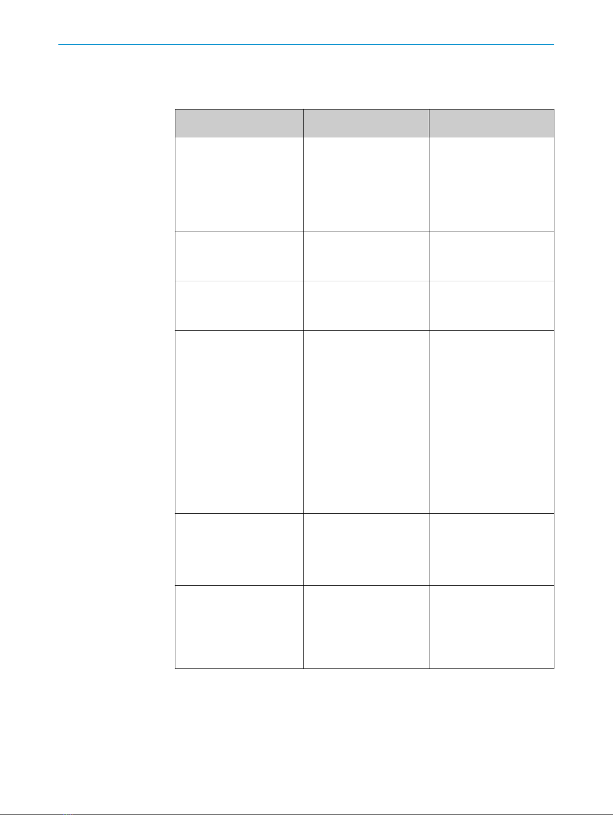
6 Table Fault diagnosis
LED indicator/fault pattern /
LED indicator/fault pattern
Cause /
Cause
Measures /
Measures
Green LED does not light up /
Green LED does not light up
No voltage or voltage below
the limit values /
No voltage or voltage below
the limit values
Check the power supply,
check all electrical connecti‐
ons (cables and plug connecti‐
ons) /
Check the power supply,
check all electrical connecti‐
ons (cables and plug connecti‐
ons)
Green LED does not light up /
Green LED does not light up
Voltage interruptions /
Voltage interruptions
Ensure there is a stable power
supply without interruptions /
Ensure there is a stable power
supply without interruptions
Green LED does not light up /
Green LED does not light up
Sensor is faulty /
Sensor is faulty
If the power supply is OK, re‐
place the sensor /
If the power supply is OK, re‐
place the sensor
Yellow LED flashes /
Yellow LED flashes
Sensor is still ready for opera‐
tion, but the operating conditi‐
ons are not ideal /
Sensor is still ready for opera‐
tion, but the operating conditi‐
ons are not ideal
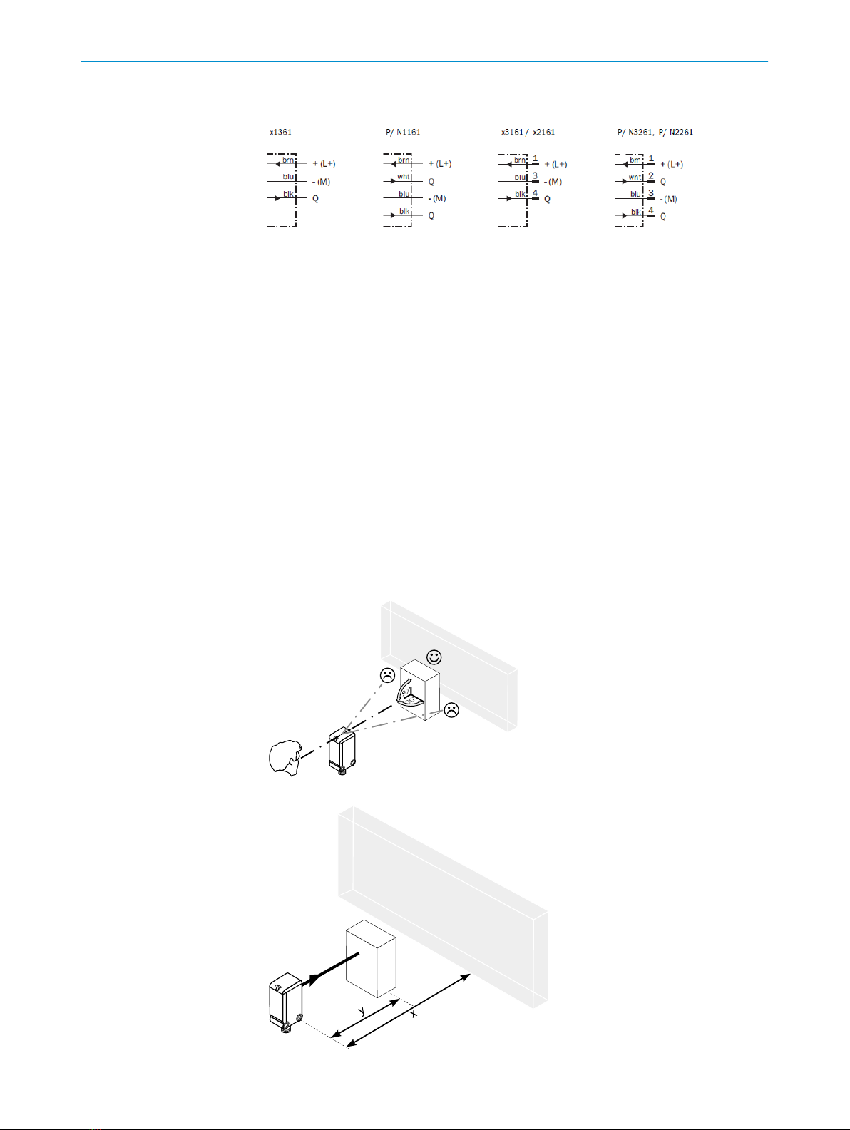
Check the operating conditi‐
ons: Fully align the beam of
light (light spot) with the ob‐
ject. / Clean the optical surfa‐
ces . / Readjust the sensitivity
(potentiometer) / Check sen‐
sing range and adjust if ne‐
cessary; see graphic F. /
Check the operating conditi‐
ons: Fully align the beam of
light (light spot) with the ob‐
ject. / Clean the optical surfa‐
ces . / Readjust the sensitivity
(potentiometer) / Check sen‐
sing range and adjust if ne‐
cessary; see graphic F.
Yellow LED lights up, no object
in the path of the beam /
Yellow LED lights up, no object
in the path of the beam
/ Distance between the sen‐
sor and the background is too
short /
/ Distance between the sen‐
sor and the background is too
short
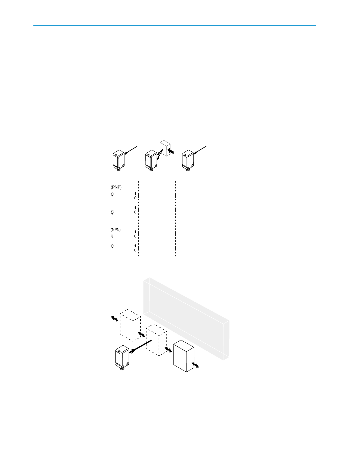
Reduce the sensing range,
see graphic F /
Reduce the sensing range,
see graphic F
Object is in the path of the be‐
am, yellow LED does not light
up /
Object is in the path of the be‐
am, yellow LED does not light
up
Distance between the sensor
and the object is too long or
sensing range is set too
short /
Distance between the sensor
and the object is too long or
sensing range is set too short
Increase the sensing range,
see graphic F /
Increase the sensing range,
see graphic F
7 Disassembly and disposal
The sensor must be disposed of according to the applicable country-specific regulati‐
ons. Efforts should be made during the disposal process to recycle the constituent ma‐
terials (particularly precious metals).
6 TABLE FAULT DIAGNOSIS
48012134.10DT | SICK
Subject to change without notice