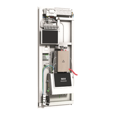
SICK MCS200HW User manual

OPERATING INSTRUCTIONS
MCS200HW
Multicomponent Analysis System

Described product
MCS200HW
Manufacturer
SICK AG
Erwin-Sick-Str. 1
79183 Waldkirch
Germany
Legal information
This work is protected by copyright. Any rights derived from the copyright shall be
reserved for SICK AG. Reproduction of this document or parts of this document is
only permissible within the limits of the legal determination of Copyright Law. Any modi‐
fication, abridgment or translation of this document is prohibited without the express
written permission of SICK AG.
The trademarks stated in this document are the property of their respective owner.
© SICK AG. All rights reserved.
Original document
This document is an original document of SICK AG.
2O P E R A T I N G I N S T R U C T I O N S | MCS200HW 8021889/1D1T/V3-1/2021-09 | SICK
Subject to change without notice

Contents
1 About this document........................................................................ 7
1.1 Function of this document....................................................................... 7
1.2 Scope of application................................................................................. 7
1.3 Target groups............................................................................................ 7
1.4 Further information................................................................................... 7
1.5 Symbols and document conventions...................................................... 7
1.5.1 Warning symbols...................................................................... 7
1.5.2 Warning levels / Signal words................................................. 8
1.5.3 Information symbols................................................................ 8
1.6 Data integrity............................................................................................. 8
2 Safety information............................................................................ 9
2.1 Basic safety information........................................................................... 9
2.2 Warning information on device................................................................ 10
2.3 Intended use............................................................................................. 11
2.4 Requirements on the personnel's qualification...................................... 11
3 Product description........................................................................... 13
3.1 Product identification............................................................................... 13
3.2 Gas supply terminology............................................................................ 14
3.3 Layout and function.................................................................................. 14
3.3.1 System overview...................................................................... 14
3.3.2 Analyzer cabinet....................................................................... 15
3.3.3 Gas sampling unit.................................................................... 17
3.3.4 Sample gas line, heated.......................................................... 17
3.3.5 Instrument air, conditioning.................................................... 18
3.3.6 Integrated GMS811 FIDORi (option)...................................... 18
3.3.7 Cooling unit (option)................................................................ 19
3.4 Extended interfaces (option).................................................................... 19
3.5 Remote maintenance (option)................................................................. 19
4 Transport and storage....................................................................... 20
4.1 Transport................................................................................................... 20
4.2 Storage...................................................................................................... 21
5 Mounting............................................................................................. 22
5.1 Safety......................................................................................................... 22
5.2 Scope of delivery....................................................................................... 22
5.3 Overview of mechanical and electrical installation................................ 22
5.4 Installation sequence............................................................................... 23
5.4.1 Installing the analyzer cabinet................................................ 23
5.4.2 Installing the sample gas line................................................. 24
5.4.2.1 Laying the sample gas lines................................... 24
CONTENTS
8021889/1D1T/V3-1/2021-09 | SICK O P E R A T I N G I N S T R U C T I O N S | MCS200HW 3
Subject to change without notice

5.4.2.2 Connecting the heated sample gas line to the
analyzer................................................................... 25
5.4.3 Installing the stainless steel screw fitting.............................. 25
5.4.4 Using a push-in fitting (pneumatic)........................................ 26
5.4.5 Laying the hose bundle line.................................................... 26
5.4.6 Connecting the signal lines on the analyzer.......................... 27
5.4.7 Setting the pressure reducer module.................................... 27
5.4.8 Connecting the valve block..................................................... 28
5.4.9 Connecting the span gases..................................................... 29
5.4.10 Connecting the exhaust gas outlet......................................... 30
6 Electrical installation........................................................................ 31
6.1 Safety......................................................................................................... 31
6.2 Equipment protection............................................................................... 31
6.3 Disconnecting device................................................................................ 31
6.4 Socket for Service work............................................................................ 31
6.5 Connecting the power supply................................................................... 31
6.6 Performing a high voltage test................................................................. 32
6.7 Connecting the signal line (option).......................................................... 32
6.8 Connecting Ethernet (option)................................................................... 33
7 Commissioning.................................................................................. 34
7.1 Prerequisites for switching on.................................................................. 34
7.2 Switching on.............................................................................................. 34
7.3 Recognizing the safe operating state...................................................... 34
7.4 Adjusting.................................................................................................... 34
7.4.1 Performing zero point adjustment.......................................... 34
7.4.2 Performing reference point adjustment................................. 35
7.4.2.1 Adjustment with internal adjustment filter........... 35
7.4.2.2 Adjustment with span gas...................................... 35
7.4.2.3 O2 adjustment......................................................... 36
8 Operation............................................................................................ 37
8.1 Operating concept.................................................................................... 37
8.2 User groups............................................................................................... 37
8.3 Display....................................................................................................... 37
8.4 Tiles........................................................................................................... 38
8.5 Measuring Screen..................................................................................... 39
9 Menus.................................................................................................. 41
9.1 Password................................................................................................... 41
9.2 Menu tree.................................................................................................. 41
10 Maintenance...................................................................................... 45
10.1 Safety......................................................................................................... 45
10.2 Important information.............................................................................. 45
10.3 Cleaning..................................................................................................... 46
CONTENTS
4O P E R A T I N G I N S T R U C T I O N S | MCS200HW 8021889/1D1T/V3-1/2021-09 | SICK
Subject to change without notice

10.3.1 Clean surfaces and parts with media contact....................... 46
10.3.2 Cleaning the display................................................................ 47
10.4 Maintenance plan..................................................................................... 47
10.5 Checking the system................................................................................ 48
10.5.1 Check assemblies.................................................................... 48
10.5.2 Check external instrument air supply..................................... 48
10.5.3 Check span gases.................................................................... 49
10.5.4 Check environment.................................................................. 49
10.5.5 Check gas sampling unit......................................................... 49
10.5.6 Check measured values (when system in operation)........... 49
10.6 Maintaining the instrument air conditioning.......................................... 49
10.6.1 Maintaining the instrument air conditioning (option)............ 49
10.6.2 Maintaining the external instrument air conditioning
(option)..................................................................................... 49
10.7 Replacing the filter pad............................................................................ 50
10.7.1 Replacing the filter mat of the roof fan grill........................... 50
10.7.2 Replacing the filter pad........................................................... 51
11 Troubleshooting................................................................................. 52
11.1 Safety......................................................................................................... 52
11.2 Important information.............................................................................. 52
11.3 Error messages and possible causes..................................................... 52
11.4 Replacing the Electronics module filter pad........................................... 57
12 Decommissioning............................................................................. 58
12.1 Switching off.............................................................................................. 58
12.1.1 Switching off............................................................................. 58
12.1.2 Shutdown................................................................................. 58
12.2 Return delivery.......................................................................................... 58
12.2.1 Shipping for repair................................................................... 58
12.2.2 Cleaning the device before returning..................................... 59
12.3 Transport................................................................................................... 59
12.4 Disposal..................................................................................................... 59
13 Technical data.................................................................................... 60
13.1 Dimensional drawings.............................................................................. 60
13.2 Technical data........................................................................................... 62
13.2.1 Measured values..................................................................... 62
13.2.2 Ambient conditions.................................................................. 63
13.2.3 Housing.................................................................................... 64
13.2.4 Interfaces and protocols......................................................... 64
13.2.5 Power supply............................................................................ 64
13.2.6 Gas supply................................................................................ 65
13.2.7 Tube connections..................................................................... 65
13.2.8 Sample gas conditions............................................................ 65
13.2.9 Connections in analyzer.......................................................... 66
CONTENTS
8021889/1D1T/V3-1/2021-09 | SICK O P E R A T I N G I N S T R U C T I O N S | MCS200HW 5
Subject to change without notice


13.2.9.1 Power supply - connection / fuses........................ 66
13.2.9.2 Electronics fuses..................................................... 66
13.2.9.3 Connections for heated components.................... 67
13.2.9.4 Connections for interfaces and SD card............... 69
13.2.10 Heated sample gas line........................................................... 71
13.2.11 Switching on the circuit breakers again................................. 71
13.2.12 Torques for screw fittings........................................................ 71
14 Annex.................................................................................................. 73
14.1 Conformities.............................................................................................. 73
14.2 Licenses.................................................................................................... 73
14.2.1 Liability disclaimer................................................................... 73
14.2.2 Software licences.................................................................... 73
14.2.3 Source codes........................................................................... 73
CONTENTS
6O P E R A T I N G I N S T R U C T I O N S | MCS200HW 8021889/1D1T/V3-1/2021-09 | SICK
Subject to change without notice

1 About this document
1.1 Function of this document
These Operating Instructions describe:
•Device components
•Installation
•Commissioning
•Operation
•Maintenance work required for reliable operation
•Troubleshooting
•Decommissioning
1.2 Scope of application
These Operating Instructions are only applicable for the measuring device described in
the product identification.
They are not applicable for other SICK measuring devices.
The standards referred to in these Operating Instructions are to be observed in the
respective valid version.
1.3 Target groups
This Manual is intended for persons who install, commission, operate and maintain the
device.
1.4 Further information
•SFU Gas Sampling Unit Operating Instructions
•Sample Gas Line Operating Instructions
•System documentation
•Option: MPR (Meeting Point Router) Operating Instructions
•Option: Instrument Air Conditioning Operating Instructions
•Option: GMS800 FIDOR / FIDORi Operating Instructions
•Option: Condensate Container Operating Instructions
•Option: Cooling Unit Operating Instructions
1.5 Symbols and document conventions
1.5.1 Warning symbols
Table 1: Warning symbols
Symbol Significance
Hazard (general)
Hazard by electrical voltage
Hazard by acidic substances
ABOUT THIS DOCUMENT 1
8021889/1D1T/V3-1/2021-09 | SICK O P E R A T I N G I N S T R U C T I O N S | MCS200HW 7
Subject to change without notice

Symbol Significance
Hazard by toxic substances
Hazard through hot surface
Hazard for the environment/nature/organic life
1.5.2 Warning levels / Signal words
DANGER
Risk or hazardous situation which will result in severe personal injury or death.
WARNING
Risk or hazardous situation which could result in severe personal injury or death.
CAUTION
Hazard or unsafe practice which could result in less severe or minor injuries.
Notice
Hazard which could result in property damage.
Note
Hints
1.5.3 Information symbols
Table 2: Information symbols
Symbol Significance
Important technical information for this product
Important information for electrical or electronic functions
1.6 Data integrity
SICK AG uses standardized data interfaces, such as standard IP technology, in its
products. The focus here is on product availability and features.
SICK AG always assumes that the customer is responsible for the integrity and confi‐
dentiality of data and rights involved in connection with using the products.
In all cases, the customer is responsible for the implementation of safety measures
suitable for the respective situation, e.g., network separation, firewalls, virus protection
and Patch Management.
1 ABOUT THIS DOCUMENT
8O P E R A T I N G I N S T R U C T I O N S | MCS200HW 8021889/1D1T/V3-1/2021-09 | SICK
Subject to change without notice

2 Safety information
2.1 Basic safety information
bRead and observe these Operating Instructions.
bObserve all safety instructions.
bIf anything is not clear: Please contact SICK Customer Service.
Document retention
These Operating Instructions
bMust be kept for reference.
bMust be passed on to new owners.
Correct project planning
•Basis of this Manual is the delivery of the measuring device according to the
preceding project planning (e.g., based on the SICK application questionnaire)
and the relevant delivery state of the measuring device (see delivered System
Documentation).
bContact SICK Customer Service if you are not sure whether the measuring
device corresponds to the state defined during project planning or to the
delivered System Documentation.
Correct use
bUse the device only as described in “Intended use”.
The manufacturer assumes no responsibility for any other use.
bCarry out the specified maintenance work.
bDo not carry out any work or repairs on the device that are not described in this
Manual.
Do not remove, add or change any components in or on the device unless such
changes are officially allowed and specified by the manufacturer.
If you do not observe this:
°The manufacturer's warranty becomes void.
°The device could become dangerous.
Special local conditions
In addition to the information in this Manual, follow all local laws, technical rules and
company-internal operating and installation directives applicable wherever the device is
installed.
SAFETY INFORMATION 2
8021889/1D1T/V3-1/2021-09 | SICK O P E R A T I N G I N S T R U C T I O N S | MCS200HW 9
Subject to change without notice

Electrical safety
DANGER
Danger to life through electric shock
There is a risk of electric shock when working on the device with the voltage supply
switched on.
bBefore starting work on the device, ensure the voltage supply can be switched
off in accordance with the valid Standard using a power isolating switch/circuit
breaker.
bMake sure the disconnector switch is easily accessible.
bAn additional disconnecting device is mandatory when the power disconnector
switch cannot be accessed or only with difficulty after installation of the device
connection.
bSwitch off the voltage supply before starting any work on the device.
bAfter completion of the work or for test purposes, calibration of the power supply
may only be activated again by authorized personnel complying with the safety
regulations.
WARNING
Endangerment of electrical safety through power supply line with incorrect rating
Electrical accidents can occur when the specifications for installation of a power supply
line have not been adequately observed.
bAlways observe the exact specifications in the Operating Instructions (see "Techni‐
cal data", page 60) for installation of a power supply line.
Dangerous substances
DANGER
Danger to life through leaks in the gas path
When the measuring device is used to measure toxic gases: A leak, for example in the
purge air supply, can be an acute hazard for persons..
bRegularly check all gas-carrying components for leaks
bTake suitable safety measures. For example:
°Attach warning signs to the device
°Attach warning signs in the operating area
°Adequately vent the operating area.
°Safety-oriented instruction of persons that could be in this area.
2.2 Warning information on device
Warning information on device
The following safety symbols are on the device:
Table 3: Warning symbols
Symbol Significance
Warning for general hazard
Warning for hazard by electric voltage, possibly also by residual electric voltage
2 SAFETY INFORMATION
10 O P E R A T I N G I N S T R U C T I O N S | MCS200HW 8021889/1D1T/V3-1/2021-09 | SICK
Subject to change without notice

Symbol Significance
Warning for hazard through hot surfaces
If you need to work on a subassembly marked with such a symbol:
bRead the relevant Section in these Operating Instructions
bObserve all the safety information in the relevant Section
2.3 Intended use
The MCS200HW is a multicomponent analysis system for continuous flue gas moni‐
toring of industrial combustion plants (emission measuring system). The sample gas
is extracted at the measuring point and fed through the analysis system (extractive
measurement).
The analysis system is designed for indoor installation.
bRefer to the system documentation delivered for information on the device equip‐
ment.
2.4 Requirements on the personnel's qualification
Table 4: Qualification requirements
Tasks User groups Qualifications
Installation Qualified personnel •General knowledge in
measurement technology,
specialist device knowledge
(possibly customer training
at SICK)
Electrical Installation Qualified personnel •Authorized electrician
(authorized skilled electri‐
cian or person with similar
training)
•General knowledge in
measurement technology,
specialist device knowledge
(possibly customer training
at SICK)
Initial commissioning Authorized operator ܕGeneral knowledge in
measurement technology,
specialist device knowledge
(possibly customer training
at SICK)
Recommissioning
Decommissioning •Operator / system integra‐
tor
•Authorized operator Ü
•General knowledge in
measurement technology,
specialist device knowledge
(possibly customer training
at SICK)
•Authorized electrician
(authorized skilled electri‐
cian or person with similar
training)
•Service training
Operation
Troubleshooting
SAFETY INFORMATION 2
8021889/1D1T/V3-1/2021-09 | SICK O P E R A T I N G I N S T R U C T I O N S | MCS200HW 11
Subject to change without notice

Tasks User groups Qualifications
Maintenance •Operator / system integra‐
tor
•Authorized operator Ü
•General knowledge in
measurement technology,
specialist device knowledge
(possibly customer training
at SICK)
•Service training
2 SAFETY INFORMATION
12 O P E R A T I N G I N S T R U C T I O N S | MCS200HW 8021889/1D1T/V3-1/2021-09 | SICK
Subject to change without notice

3 Product description
3.1 Product identification
Overview
Product name MCS200HW
Manufacturer SICK AG
Erwin-Sick-Str. 1 · D-79183 Waldkirch · Germany
Type plate Type plates are located outside on the right of the enclosure.
The second type plate states the integrated measuring modules.
An additional copy of the type plate can be found on the inside of
the cabinet.
MCS200HW type plates
Figure 1: Type plate of complete device, schematic representation
1Product name
2Item number
3Specification on voltage supply
4Serial number
5Barcode
6Measuring modules
Analyzer type plate
Figure 2: Analyzer type plate, schematic representation
1Product name
2Item number
3Specification on voltage supply
4Serial number
5Barcode
PRODUCT DESCRIPTION 3
8021889/1D1T/V3-1/2021-09 | SICK O P E R A T I N G I N S T R U C T I O N S | MCS200HW 13
Subject to change without notice

3.2 Gas supply terminology
Definition of utility gases:
•Zero gas: Gas to adjust the zero point. Instrument air or nitrogen (N2)
•Span gas: Gas to adjust the measuring range full scale value
•Instrument air: Compressed air free of oil, water and particles
3.3 Layout and function
3.3.1 System overview
Overview
1
2
3
4
56
7
8
1Gas sampling unit
2Heated sample gas line
3Hose bundle line
4Analyzer cabinet
5Voltage supply
6Interfaces 1 x Ethernet: Connections
Customer-specific analog and digital inputs
and outputs, see wiring diagram
7Instrument air inlet
Option: Instrument air conditioning
Observe the quality of the operator's instru‐
ment air:
A separate instrument air supply can also be
connected as zero gas (IR components) or
span gas (O2 sensor).
8Exhaust gas outlet
3 PRODUCT DESCRIPTION
14 O P E R A T I N G I N S T R U C T I O N S | MCS200HW 8021889/1D1T/V3-1/2021-09 | SICK
Subject to change without notice

Measuring principle
•IR components: Single-beam infrared photometer with interference filter and gas
filter correlation method
•Oxygen: Zirconium dioxide sensor
Measuring components
Output of measured values in mg/m³ or percentage volume, relative to humid flue gas.
Refer to the system documentation provided for the configuration of your system.
Function
•The system operates independently.
•Sampling of flue gas at the measuring point with a heated gas sampling unit
•Sample gas feed to the analyzer in a heated sample gas line
•Heating temperature of all parts with sample gas contact: 200 °C
•Pump: Ejector pump in cell (operated with instrument air)
•The analysis system uses status indicators to signal the current operating state:
•The analysis system switches to operating state “System Stop” automatically when
a malfunction occurs
“System Stop” corresponds to classification “Failure”:
°The sample gas line and the sample gas path in the analyzer are automati‐
cally purged with instrument air in this mode.
°Measured values are updated further.
Check (validation) and adjustment
•Zero point adjustment
•Reference point adjustment
•Adjustment with internal adjustment filter
Operating using the display
It is possible to operate the device using the display.
Operation via external PC (optional)
Operator menus and measured value displays are also available for easy use on an
external PC via the Ethernet connection (with Google Chrome browser and SOPAS Air).
3.3.2 Analyzer cabinet
Overview
The analyzer cabinet contains:
•Control unit
•Measurement technology
•Analog and digital interfaces
PRODUCT DESCRIPTION 3
8021889/1D1T/V3-1/2021-09 | SICK O P E R A T I N G I N S T R U C T I O N S | MCS200HW 15
Subject to change without notice

View
Figure 3: Basic configuration of analyzer cabinet
Analyzer module
1Cell module
•Ejector pump
•Inlet filter
2Optics module
3Electronics module
Analyzer cabinet
4Sample gas inlet (heated sample gas line)
5Hose bundle line
6Valve block
7Pressure reducer module
Notice: Observe the quality of the operator's instrument air.
8Sample gas outlet
9I/O modules
3 PRODUCT DESCRIPTION
16 O P E R A T I N G I N S T R U C T I O N S | MCS200HW 8021889/1D1T/V3-1/2021-09 | SICK
Subject to change without notice
3.3.3 Gas sampling unit
Overview
1
2
3
4
1Filter housing
2Gas sampling tube (unheated)
3Weather hood
4Pre-filter (optional)
Function
The gas extraction unit SFU extracts flue gas from the stack via the gas sampling tube.
After filtration, the flue gas is passed to a measuring device for analysis.
Characteristics
•The gas sampling tube is unheated and without pre-filter
•The gas sampling tube is available in different lengths (option)
•The gas sampling unit is thermostatically controlled.
•The analyzer regulates the heaters.
•When no voltage is applied, the heated sample gas line and the analyzer are
purged with instrument air.
3.3.4 Sample gas line, heated
Overview
1
5
4
7
6
3 2
Figure 4: Heated sample gas line
1Connection to gas sampling unit (without electrical connections)
2Connection to measuring device (with electrical connections)
3Protective cap
4PT100 connections
PRODUCT DESCRIPTION 3
8021889/1D1T/V3-1/2021-09 | SICK O P E R A T I N G I N S T R U C T I O N S | MCS200HW 17
Subject to change without notice

5Power supply
6Cable gland
7Locknut
Function
The heated sample gas line leads the flue gas from the gas sampling unit to the
measuring device.
Characteristics
•The sample gas line is thermostatted to prevent condensation of the flue gas.
•The measuring device regulates the heating.
•When free from voltage, the heated sample gas line is purged with instrument air.
3.3.5 Instrument air, conditioning
Overview
If the supplied instrument air does not meet the required quality, an instrument air
conditioner can be connected upstream from the pressure reducer module.
Important information
NOTICE
Malfunction of the measuring device due to unsuitable instrument air
Operation with air not satisfying the specifications voids the warranty and does not
ensure proper functioning of the measuring device.
bOnly feed conditioned instrument air to the measuring device.
bThe instrument air quality must meet the specification.
Function
The instrument air conditioning serves to condition the compressed air provided by the
operator.
Additional information
A separate instrument air supply as zero gas or test gas can be connected as an
alternative.
Related topics
•Instrument Air Conditioning Operating Instructions
•Instrument air quality: see "Gas supply", page 65
3.3.6 Integrated GMS811 FIDORi (option)
As an option, the device can be equipped with an integrated GMS811 FIDORi for meas‐
uring the total carbon (TOC). Measured values and operating states can be displayed
using the display.
If the GMS811 FIDORi is integrated, it is stated as “TOC” module on the type plate .
Additional information
•GMS800 FIDOR / FIDORi Operating Instructions
3 PRODUCT DESCRIPTION
18 O P E R A T I N G I N S T R U C T I O N S | MCS200HW 8021889/1D1T/V3-1/2021-09 | SICK
Subject to change without notice

3.3.7 Cooling unit (option)
The analyzer can optionally be operated with a cooling unit. This extends the tempera‐
ture range to +5 °C ... +50 °C.
Additional information
•Cooling Unit Operating Instructions
3.4 Extended interfaces (option)
As standard, analog and digital signals are used for device communication with cus‐
tomer peripherals. Alternatively, output can be performed using the Modbus-TCP proto‐
col.
Optionally, SICK offers various converter modules that are installed by the customer
and communicate with the device via Modbus® TCP.
Optionally available
•PROFIBUS / PROFINET
Modbus
Modbus® is a communication standard for digital controls to create a connection
between a »Master« device and several »Slave« devices. The Modbus protocol defines
the communication commands only but not their electronic transfer; therefore it can be
used with different digital interfaces (Ethernet).
The measuring device is equipped with a digital interface for data transmission in
accordance with Guideline VDI 4201, Sheet 1 (General requirements) and Sheet 3
(Specific requirements for Modbus). Refer to the documentation delivered (Modbus
signal list) for assignment of the Modbus registers. Only SICK Service may perform
parameter settings.
3.5 Remote maintenance (option)
Prerequisites
•An internet connection must be available.
Function
•The SICK Meeting Point Router (MPR) is available for remote diagnostics via the
internet.
•The MPR links a plant-side machine network with the SICK remote architecture.
•A firewall which decouples the machine network from the internet or the operating
company network is integrated in the MPR.
Related topics
•MPR Meeting Point Router Operating Instructions
PRODUCT DESCRIPTION 3
8021889/1D1T/V3-1/2021-09 | SICK O P E R A T I N G I N S T R U C T I O N S | MCS200HW 19
Subject to change without notice
4 Transport and storage
4.1 Transport
Overview
Transport and install the device with suitable hoisting equipment (e.g. a crane or jack
lift with adequate lifting capacity).
Important information
NOTICE
The measuring device may only be transported and installed by qualified persons who,
based on their training and knowledge as well as knowledge of the relevant regulations,
can assess the tasks given and recognize the dangers involved.
Transport via crane
Analyzer cabinets are transported safely with delivered lifting lugs. The following permis‐
sible total loads apply for symmetrical loads:
•For 45° cable pull angle 4 800 N
•For 60° cable pull angle 6 400 N
•For 90° cable pull angle 13 600 N
4 TRANSPORT AND STORAGE
20 O P E R A T I N G I N S T R U C T I O N S | MCS200HW 8021889/1D1T/V3-1/2021-09 | SICK
Subject to change without notice
Other manuals for MCS200HW
2
Table of contents
Other SICK Analytical Instrument manuals

SICK
SICK MCS200HW User manual

SICK
SICK MCS200HW-MP User manual

SICK
SICK ZIRKOR200 Ex-G User manual

SICK
SICK MCS300P User manual

SICK
SICK DL100 Pro User manual

SICK
SICK InspectorP621 User manual

SICK
SICK VICOTEC320 Series User manual

SICK
SICK MCS300P Manual

SICK
SICK InspectorP621 User manual

SICK
SICK Master Data Analyzer Vision User manual