sidhil Freedom II User manual

Instructions for use
4 Section Profiling Bed
www.sidhil.com
Freedom II
Electrically Operated Profiling Bed
Freedom II


3
Still making it better...
Welcome to Sidhil
Excellence in customer
service is our key objective.
Alongside our focus on
innovation, research and
product development, we
use our UK manufacturing
facility to ensure optimum
levels of product and
spares availability, with
unparalleled levels of
reliability and performance.
Corporate social responsibility
is also an issue for Sidhil. We
have now received accreditation
to ISO 14001, underlining our
commitment to maintaining the
highest levels of environmental
awareness and sustainability across
our manufacturing operation.
At Sidhil, everything we do
is designed around quality.
From our modern and efficient
manufacturing plant in Halifax,
West Yorkshire, we manufacture
a range of products for the
healthcare market using leading
edge production technology and
finishing processes.
We are the only remaining
volume manufacturer of
hospital beds in the UK,
bringing together innovation in
product development, sales,
customer service and logistics
to provide clear benefits for
our customers in terms of
flexibility, short production
timescales and support for our
nationwide network of service
and maintenance centres.

4
1. INTRODUCTION .............................................................................. 5
1.1 Features ..............................................................................................5
1.2 Warnings and Cautions ........................................................................ 5
2. USE.....................................................................................................6
2.1 Typical Use .......................................................................................... 6
2.2 Risk Assessment ................................................................................. .6
2.3 Bed Load ............................................................................................. 6
2.4 General Warning ................................................................................. 6
3. SYMBOL DEFINITION ...................................................................... 7
4. PARTS IDENTIFICATION ................................................................. 8
5. BED ASSEMBLY AND PREPARING FOR USE ................................... 9
5.1 Removal From the Transport Stand ...................................................... 9
5.2 Assembling the Bed ..............................................................................10
5.3 Fitting the Electrical System ..................................................................11
5.4 Fitting the Side Rails .............................................................................12
5.5 Checking the Bed ................................................................................ 14
6. OPERATION OF THE BED ................................................................ 15
6.1 General Safety .....................................................................................15
6.2 Preparing For Use................................................................................15
6.3 Brake System ...................................................................................... 16
6.4 Side Rails ............................................................................................. 16
6.4.1 Mattress Thickness................................................................ 16
6.4.2 Operating the Side Rails.............................................................. 17
6.5 Electrical Operation ............................................................................ 18
6.5.1 Handset Functions (Twist Key Model).....................................18
6.5.2 Lockout Functions (Twist Key Model).....................................18
6.5.3 Handset Functions (Magnetic Key Model)...............................19
6.5.4 Handset Functions (Magnetic Key Model)...............................19
6.6 Knee Break / Leg Section ..................................................................... 20
7. ASSEMBLY ONTO THE TRANSPORT STAND ................................. 21
8. POWER FAILURES ............................................................................. 23
9. DECONTAMINATION ....................................................................... 24
9.1 Cleaning and Disinfection Guidelines .................................................... 24
9.2 Steam Cleaning .....................................................................................25
10. MAINTENANCE .............................................................................. 26
10.1 Fault Finding ....................................................................................... 27
10.2 General Maintenance ......................................................................... 28
11. SPECIFICATION .............................................................................. 29
11.1 Bed Data ............................................................................................ 29
11.2 Electrical Data ....................................................................................30
12. WARRANTY ..................................................................................... 31
CONTENTS

5
Thank you for purchasing this product. These instructions for use should be read
carefully before operating the bed. Please ensure that you understand all instructions,
if you have any questions concerning the operation or maintenance of the bed please
contact your provider / supplier who will provide you with expert professional advice.
1. INTRODUCTION
1.1 Features
• Electricallyoperatedbackrest,heightandkneebreakangle
• Infinitelyvariableelectricallyoperatedfootdowntilt
• Autocontour–simultaneousadjustmentofthebackrestandkneebreak
• Patienthandsetwithintegralfunctionlockout
• Bedbreaksdownintofourseparatesections
• Integralfulllengthsiderails
• Transportstandtoaidstorageandbedtransportation
1.2 Warnings and Cautions
Warnings in these instructions for use highlight potential hazards that if
disregarded could lead to injury or death.
Cautions in these instructions for use highlight potential hazards that if
disregarded could lead to equipment damage or failure.
Warning
Caution
6
2. USE
2.1 Typical Use
Your bed is intended for use within the home environment. It has been designed
to provide users with optimum independence and freedom of movement through
the use of a touch button handset. The bed offers greatly reduced manual handling
requirements for the carer by providing a bed with a fully profiling platform and
electrical height adjustment capability.
2.2 Risk Assessment
Before a patient uses the bed a risk assessment must be performed on a patient by
patient basis. The risk assessment should include but is not limited to:
• Entrapment
• Fallingoutofthebed
• Smallchildren(andadults)
• Patientswithlearningdifficulties
• Unauthorisedpeople
Bed functions must be locked out if there is any doubt about the ability
of the patient to operate the bed safely.
Warning
2.3 Bed Load
The safe working load of the bed is: 213kgs (33 stone)
The maximum user weight of the bed is: 178kgs (28 stone)
2.4 General Warning
• Misusedelectricalequipmentcanbehazardous.
• Accessoriesthathavenotbeenapprovedordesignedforusewith
the bed should not be used.
• Electricallyoperatedbedsshouldnotbeusedinthepresenceof
flammable gasses.
Warning
7
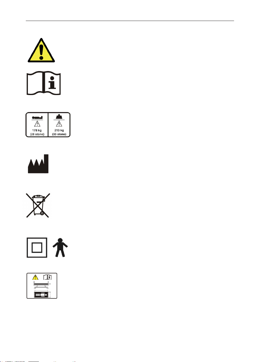
3. SYMBOL DEFINITION
The following symbols are found on this bed:
Warning
Beware of potential hazard
Refer to instructions for use - Recommended
Failure to read the instructions for use could introduce a hazard
Maximum patient weight & Safe working load
Place of manufacture
W.E.E.E Label - Found on individual parts of electrical system
(Waste Electrical and Electrical Equipment)
Class II, Type B
Refer to instructions for use for mattress suitability
Use of an incorrectly specified mattress could introduce a hazard

8
4. PARTS IDENTIFICATION
1. Head/foot end
2. Castor
3. Handset
4. Lockout fob
5. Control box & knee break actuator
6. Leg section
7. Locking collar
8. Hi/low actuator
9. Side rail
10. Backrest actuator
11. Backrest
(Transport stand not shown)
9
Warning
• Beforeattemptingtoassemblethebedensuretheseinstructions
have been read and fully understood.
• Itisadvisabletoassemblethebedwithasecondablebodiedperson.
• Takecarewhendisassemblingthebedfromthetransportstand,the
sections are of considerable weight.
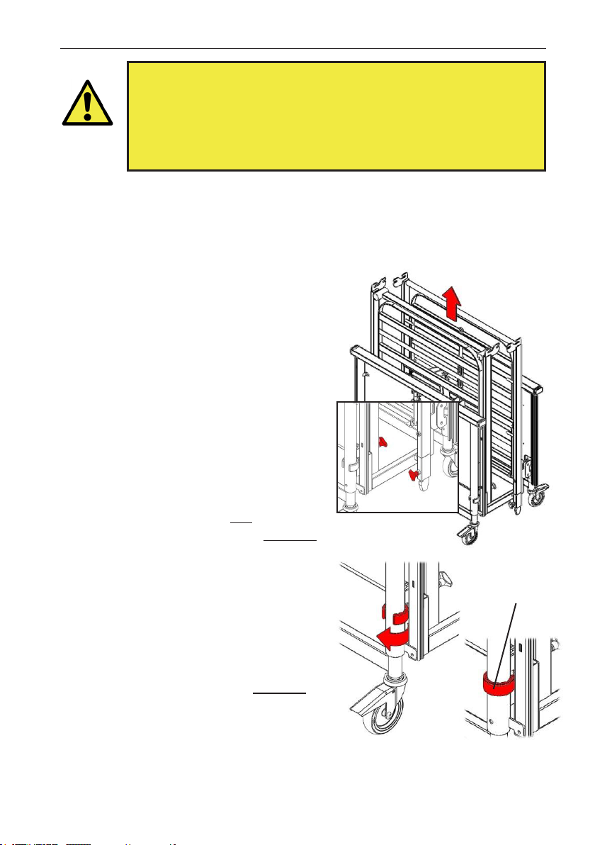
5. BED ASSEMBLY AND PREPARING FOR USE
5.1 Removal From the Transport Stand
No tools are necessary for the assembly of the bed. The assembly procedure is as
follows:
• Cleartheareaintendedforthebedofany
obstructions and ensure the surface is
level.
• Applythebrakestothecastors.
• Loosenthehandwheelsonthetransport
stand that hold the leg section in place
and then lift this section off the stand and
carefully place flat on the floor.
• Loosenthehandwheelsonthebackrest
section (attaching it to the transport
stand) and then lift this section off the stand
and carefully place flat on the floor.
• Turnthelockingcollarsonone of the bed
ends so that they are both in the unlocked
position.
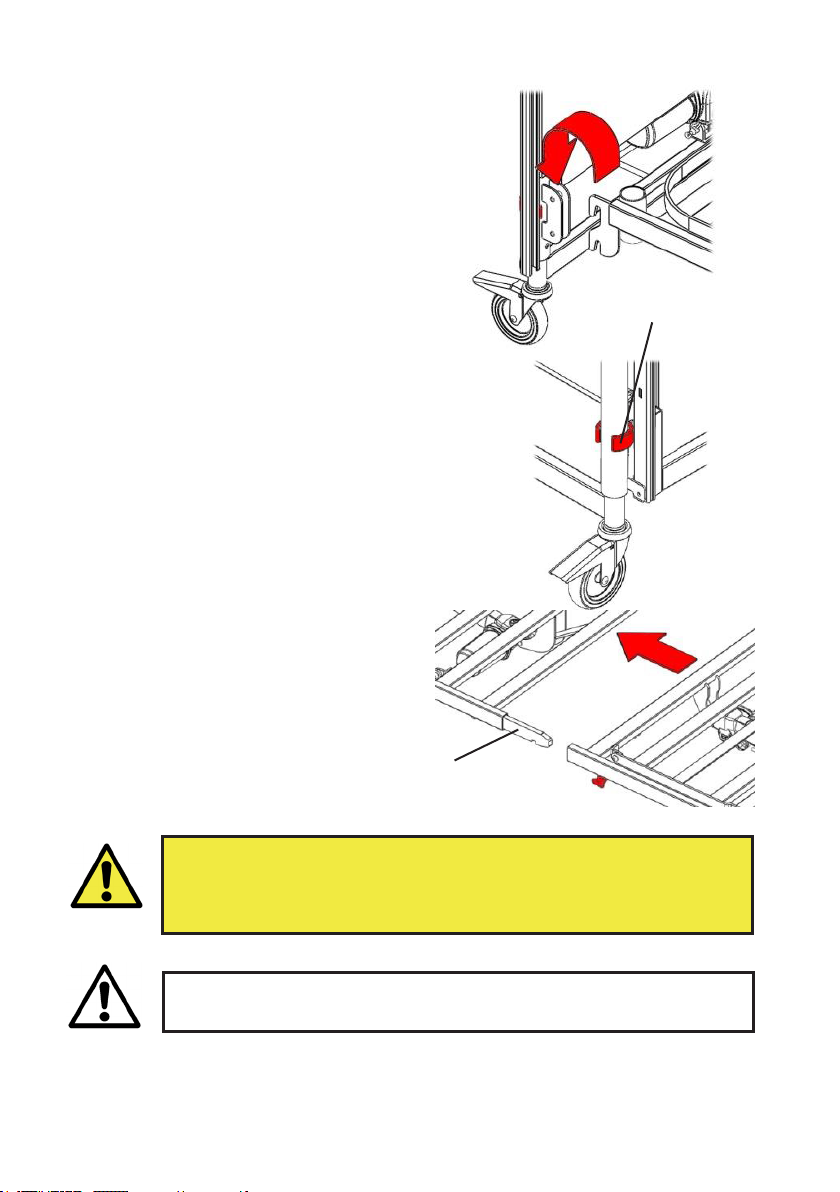
• Carefullylifttheendsofthetransport
stand away from the bed end and place
carefully against a wall or on the floor.
Note: when the transport stands are lifted
away neither bed end will be supported.
• Turnthelockingcollarsontheremaining
bed end so that they are in the unlocked
position.
• Carefullylifttheendsofthetransport
stand away from this bed end.
The bed has now been separated into its constituent parts.
Collar
unlocked
10
• The bed must never be used with the hand wheels loose or if missing.
• The bed must never be used with the locking collars in the unlocked
position or if missing.
If the bed has been supplied with tie wraps/Velcro (or similar) securing
any of the sections in place ensure they are removed prior to operation.
Warning
Caution
5.2 Assembling the Bed
• Whilstsupportingoneofthebedendslift
one of the mattress platform halves and
hook into the bed end. Turn the locking
collars into their locked position. Note:
If this action is being undertaken by a single
person Sidhil recommend that the castors
are braked before assembly commences.
• Repeatfortheremainingbedendand
mattress platform halve.
• Releasethebrakesonthecastors.
• Bringbothhalvesofthebedtogetherand
align each section so that the spigots in the
head end locate into the open tube ends in
the foot end. Pull the two sections together
and tighten the 2 hand wheels.
Collar
locked
Spigot

11
5.3 Fitting the Electrical System
• Plugtheactuatorandhandsetcablesintothecontrolbox.Thecablesare
colour matched to the graphic on the control box so using this, plug the cables into
the corresponding ports. Note, the plugs only fit into the ports in one orientation.
Ensure the cables are plugged fully into the control box.
Note: The two bed ends are identical but plugging them into the correct port is
important. Note the cable tie colour before plugging in.
• Onceallthecablesareconnectedtheyaretobesecuredinplacebyattachingthe
supplied anti-removal clip.
• Clipthemainscableintothehookontheheadendsectionofthebed.
• Ensureallcablesarefreefrommovingpartsandarenotunder
excessive tension.
• Ensure the two hi/low actuators are plugged into the correct ports, if
not the tilt function will not work correctly.
Caution
Hi/Low - Head
End Backrest
Hi/Low - Foot
End
Knee Break Handset
Mains Cable Clip

12
5.4 Fitting the Side Rails
• Raisethebedtoapproximatelythe
midpoint of its height range (see
page 18 for operation of the handset).
• Lowerthefingerassembliestotheir‘down’
position. (see page 17 for an explanation of
how to lower the fingers).
• Removethehand-wheelfromthesiderail
channel at the foot end of the bed.
• Removetheentirefingerassemblyset
from the channel (as per top right image).
• Takingthefirstsiderailslidetheendof
it into the top set of fingers that are
still located in the channel at the head end
of the bed. Carefully rest the
unattached end on the floor taking
care to ensure that the other end is
sufficiently far into the fingers so that it will
not fall out.
• Takethepreviouslyremovedassembly
and clip the wire into the top moulding
(the top moulding is identified by the
metal release catch in the middle).
Ensure the open end of the wire loop is
pointing towards the end of the
moulding with the half moon in it.
• Slidethefingersintothesiderail.
• Whilstholdingthefingersintheside
rail, with the other hand slide the
plastic slider stop into the channel. Slide
the plastic finger assembly into the
channel (after the slider stop).
Lift the assembly until a click is heard and the
mechanism locks into place, approximately
one third up the channel. Let go of the side
rail.
13
• Take the second side rail and fit this into the
remaining lower set of fingers that are still
located in the channel at the head end of the
bed. Carefully rest the unattached end on
the floor taking care to ensure that the other
end is sufficiently far into the fingers so that
it will not fall out.
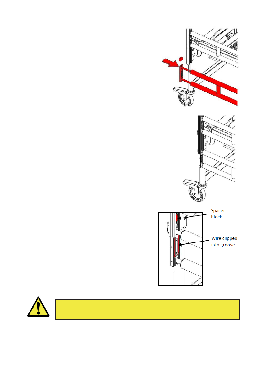
• Take the remaining finger assembly and
position the top finger through the wire
loop, so that the bottom finger is hanging
freely under the loop. (Note, if there is no
wire loop visible push it down the channel
using the slider stop).
• Lift the remaining side rail and slide the
fingers into the open end, ensuring that one
finger remains within the wire loop.
• Whilst holding the fingers in the side rail, with
the other hand slide the plastic spacer block
into the channel.
• Slide the finger assembly partially into the
channel. Clip the open end of the wire loop
into the groove that is positioned just above
the lower finger. Once clipped into place lift
the complete side rail assembly to the top of
the channel.
• Re-fit the previously removed hand-wheel.
(The hand-wheel is orientated so that
when fitted the threaded section is pointing
towards the middle of the bed.)
• Repeat the assembly process for the side rail
on the other side of the bed.
If there is any doubt about the assembly of the side rails contact the
provider of the equipment, incorrectly fitted side rails can lead to death.
Warning

14
5.5 Checking the Bed
• Arethelockingcollarsonthecornersofthebedcorrectlyorientatedinthe
locked position?
• Arethe2mattressplatformsand4siderailchannelhandwheelstight?
• Hasallpackagingbeenremovede.g.cableties/Velcrosecuringtheplatform
sections?
• Arethecablesfreeofallmovingpartsofthebedandistheresufficientslackinthe
cables to allow for movement?
• Isthebedclearofobstructions?
• Hasariskassessmentbeenperformedonthesuitabilityofthebedfortheuser?
sections?
The bed is now fully assembled. Before the bed is put into use ensure the bed is
correctly assembled:
15
Special care should be taken when fitting an air mattress to the bed as
incorrect fitting could damage the bed frame.
Caution
6. OPERATION OF THE BED
6.1 General Safety
• Whenthebedisoperated,ensurethatobstaclessuchasoverbedtablesand
other furniture are not causing an obstruction.
• Ensuretheelectricalcablesarenotintension.
• Ensurethatanymattressesusedareofthecorrectsizeandtypeandhavebeen
fitted correctly. A range of suitable pressure relieving and pressure reducing
mattresses are available from Sidhil Ltd.
• Beforeoperatingthebedensurethepatientispositionedappropriately.
• Whenapatientisleftunattendedensurethebedissetatitsminimumheight.
6.2 Preparing For Use
• Ensurethebedandallaccessoriesareatroomtemperature.
• Ensurethebedhasbeencleanedanddisinfected(page23).
• Ensurethemainscableispluggedintoanappropriatemainssocket.
• Ensurethebrakesonthecastorsattheheadendofthebedhavebeenapplied.
• Usingthehandsetensurethebedislevel(seepage18forhandsetoperation).
Prior to operating the bed for the first time the following simple checks must be
performed:
Note:iftheelectricalfunctionsdonotoperateensurethehandsethasbeen‘unlocked’
(see page 18 for handset operation).
16
6.3 Brake System
The bed has 4 braked castors.
• Toapplythebrakes:Pressthebrakepedaldown.
• Toreleasethebrakes:Liftthebrakepedalup.
6.4 Side Rails
When the bed is in use ensure the brakes on the castors at the head end of the bed have
been applied.
• If the bed is to be pushed up/down a slope it is advised that two people
move the bed, with one person at each end.
• If the bed is to be pushed with a heavy load it should be assessed
whether or not two people should move the bed, this is dependent on
the situation and load on the bed.
Warning
The bed comes as standard with full length side rails. A side rail height extension can
be ordered as an accessory.
When specifying a mattress and side rail combination a clinical assessment of the
patient’sneedsmustbecarriedoutinlinewiththelocalpolicy.
6.4.1 Mattress Thickness
• Full length side rails = 158mm maximum mattress thickness.
• Full length side rails with height extension = 270mm maximum
mattress thickness.
• Side rails must only be used with a mattress of the correct size and type
that is approved for use with this bed.
Warning
If an overlay air mattress is used it may be necessary to use a thinner foam mattress for
the combined height to maintain the 270mm dimension.
Refer to MHRA Device Bulletin DB2006 (06) ‘Safe use of bed rails’.
Side rails pose a potential entrapment hazard, please refer to side rail safety
notice, SR/PSN 01/01/1, supplied with this product.

17
6.4.2 Operating the Side Rails
• Ensure the side rails are locked in place at all times when in the raised
position.
• A risk assessment should be carried out to consider the age, condition
and size of the patient to assess the suitability of side rails.
• Side rails are not designed to act as restraints for patients.
• Side rails are not designed to be used as a patient lifting aid.
• When operating the side rails ensure they are free from obstructions,
to prevent injury/entrapment.
Warning
Caution
• Do not use the side rails to move the bed.
• When lowering do not drop the side rail.
1. Lift the side rail vertically upwards.
2. Depress the release catch.
3. Gently lower the side rail (the release
catch can be let go of when lowering the
side rail).
To lower:
1. Lift the side rail until it is heard to latch
into position at the top height.
To Raise:
18
6.5 Electrical Operation
The bed will be supplied with one of two types of handset; a magnetic key model or a
twist key model. The handset can either be operated by the occupant or carer. If the
carer is to operate the bed ensure that the occupant is made aware of the action(s)
about to take place.
Ensure a risk assessment is undertaken to ensure the suitability of the
occupant using the handset.
Warning
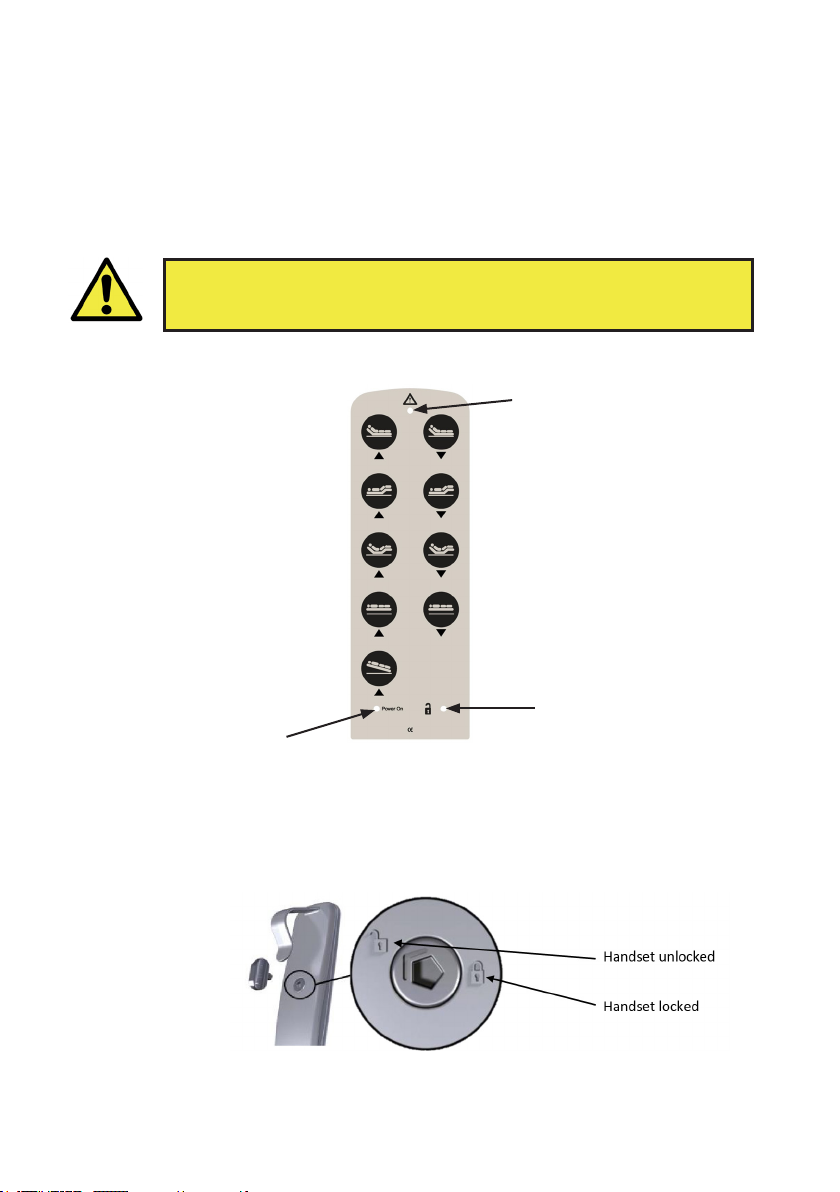
6.5.1 Handset Functions (Twist Key Model)
6.5.2 Lockout Function (Twist Key Model)
To unlock / lock the handset, turn the handset over and insert the key into the recess.
Rotate the key so that the arrow points to the unlocked / total lock position as required.
(Image courtesy of
DewertOkin GmbH)
As the key is rotated the padlock light will illuminate / extinguish as determined by
the lock state (see 6.5.1).
The handset is likely to be in the locked state when the bed is first installed.
Illuminates green when
function is operating
Backrest Up / Down
Knee Break Up/ Down
Auto Contour Up/ Down
(backrest & knee break)
Raise / Lower Mattress
Platform
Foot Down Tilt
Illuminates amber when
there is a mains power
supply
1) Handset locked:
No light illuminated
2) Handset unlocked:
Green light illuminated

19
6.5.3 Handset Functions (Magnetic Key Model)
6.5.4 Lockout Function (Magnetic Key Model)
To lock/unlock the handset, swipe the fob over the padlock symbol.
As the key is swiped over the padlock symbol the light will illuminate / extinguish as
determined by the lock state (see 6.5.3).
Illuminates green when
function is operating
Backrest Up / Down
Knee Break Up/ Down
Auto Contour Up/ Down
(backrest & knee break)
Raise / Lower Mattress
Platform
Foot Down Tilt
Illuminates amber when
there is a mains power
supply
Illuminates amber when
the handset is unlocked
(see below)

20
• Press the knee break button on the
handset and raise the knee break (height
not important).
• Lift the foot section a little so that the
ratchet engages.
• The leg section height adjustment will
now be set.
To set the bed so that the leg section is raised:
The bed is not fitted with a battery backup facility. The bed must always
be plugged into the mains supply during normal use.
Warning
6.6 Knee Break/Leg Section
Note: The operation of the knee break/leg section is dependent on the position of the
ratchet as detailed below.
The bed is fitted with an adjustable leg section. When the knee break function on the
handset is operated the height or angle of the leg section is adjusted, depending on
whether or not the leg section ratchet is set.
• Press the knee break button on the
handset and raise the leg section (height
not important).
• Lift the foot section a little so that the
ratchet disengages
• Gently lower the foot section down.
• The knee break height/angle adjustment
will now be set.
To set the bed so that the knee break is raised:
Table of contents
Other sidhil Medical Equipment manuals

sidhil
sidhil Inno V8 Low Installation instructions

sidhil
sidhil 1310 User manual

sidhil
sidhil 1531 User manual

sidhil
sidhil Artemis Instruction manual

sidhil
sidhil BARIATRIC DYNAMIC User manual

sidhil
sidhil Artemis User manual

sidhil
sidhil E-Med 1200 User manual

sidhil
sidhil E-Med 1500 User manual

sidhil
sidhil SOLITE-PRO User manual

sidhil
sidhil Lullaby User manual


