sidhil E-Med 1200 User manual

E-MED TROLLEY 1200 / 1400
USER GUIDE
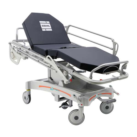
Slim two-section stretcher with adjustable height and Trendelenburg
Slim four-section stretcher with adjustable height and Trendelenburg
Sidhil Ltd, Sidhil Business Park, Holmfield, Halifax, West Yorkshire HX2 9TN
HIGH SPECIFICATION PATIENT TROLLEYS FROM SIDHIL

2
1. GENERAL PROVISIONS............................................................................... 4
1.1 Purpose of this Manual ..................................................................................... 4
1.2 Customer Service ................................................................................................ 4
1.3 Definitions ............................................................................................................ 4
2.SAFETY............................................................................................................ 5
2.1 General Rules ....................................................................................................... 5
3. INTRODUCTION ........................................................................................... 6
3.1 General Description................................................................................................ 6
3.2 Reference Standards............................................................................................... 6
3.3 Intended Use ........................................................................................................ 7
3.4 Markings ............................................................................................................... 7
4. GENERAL DESCRIPTON .............................................................................. 8
4.1 Technical Features ................................................................................................ 8
4.2 Description of the main parts - two-section stretcher E-MED 1200 ..................... 9
4.3 Description of the main parts - four-section stretcher E-MED 1400 ..................... 10
4.4 Controls Identification .......................................................................................... 11
5.INSTALLATION.............................................................................................. 12
5.1 Transportation and Handling ............................................................................... 12
5.2 Preparing the Area of Installation .......................................................................... 12
5.3 Packing List Verification ...................................................................................... 12
5.4 Checking the Equipment ................................................................................... 12
5.5 Testing ................................................................................................................... 12
5.6 Potential Equalization Connection......................................................................... 13
6. OPERATION AND USE ................................................................................ 14
6.1 Safe Position .......................................................................................................... 14
6.2 Locking the Stretcher ............................................................................................ 14
6.3 Moving the Stretcher ............................................................................................. 15
6.4 Lifting and Lowering the Stretcher ...................................................................... 17
6.5 Lifting and Lowering the Back ............................................................................. 18
6.6 Lift and Lower the Upper Leg Section (EMED1400) ........................................ 19
6.7 Movement of the Leg Section (EMED 1400) ..................................................... 20
CONTENTS
3
CONTENTS
6.8 Trendelenburg and reverse Trendelenburg ......................................................... 21
6.9 Moving the Side Rails ......................................................................................... 23
6.10 Use of the Stretcher with the Brilliance Amplifier................................................... 24
7. MAINTENANCE ............................................................................................ 25
7.1 Ordinary Maintenance ........................................................................................... 25
7.2 Cleaning ................................................................................................................ 25
7.3 Lubrication ........................................................................................................... 25
7.4 Adjusting ............................................................................................................. 26
7.5 Disinfection ......................................................................................................... 26
7.6 Sanitisation Intervals ........................................................................................... 26
7.7 Setting the Item Aside ............................................................................................ 26
7.8 Storage ................................................................................................................ 26
7.9 Disposal ................................................................................................................ 27
8. CERTIFICATE OF WARRANTY .................................................................... 28
9. ACCESSORIES ............................................................................................ 29
9.1 E-MEDIV pole......................................................................................................... 29
9.2 EMED/ACC/T0025 Monitor Support....................................................................... 33
9.3 EMED/ACC/T0080 Adjustable Armrest ............................................................... 36
9.4 BC0120 Sheet Used to Move the Patient ............................................................ 39
9.5 EMED/ACC/T0010 Antistatic Mattress ................................................................ 42
9.6 Accessory Support Rods ....................................................................................... 45
10. CERTIFICATIONS ....................................................................................... 46
11. EEC DECLARATION OF CONFORMITY ...................................................... 47

4
1.1 Purpose of this Manual
This manual is an integral part of the item. Read all warning and instructions very carefully, as they
give omportant safety precautions and information about the use and maintenance of the product.
Descriptions and illustrations contained in this publication are not binding. Sidhil reserves the right to make
any modification in order to improve this document without being obliged to update it. The illustrations
and images used in this publlication are examples only and may differ in practical application. In no event
shall the manufacturer be liable for any consequential or incidental damages, including any loss of business
profits or any other commercial damage that comes from improper use and non-compliance to the
instructions described in this manual.contact your provider/supplier who will provide you with expert
professional advice.
1.2 Customer Service
The customer and product assistance services are important parts of Sidhil company structure. Customer
service is readily available for further information on use, maintenance and service of this product.
1.3 Definitions
The following graphic and linguistic definitions have been used in this manual:
1. GENERAL PROVISIONS
Warning
Caution
This message may appear before some procedure. Failure to observe the relevant
instructions may cause damage to the machine.
This message may appear before some procedure. Failure to observe the relevant
instructions may cause damage to the machine and may result in the injury to the
operator.

5
2. SAFETY
2.1 General Rules
Warning
Improper use of the stretcher and improper maintenance can cause damage to people
or objects.
Warning
IN CASE OF BLOODTRANSMITTED DISEASES: To reduce the risk of exposure
while using the stretcher, follow the maintenance instructions written in this manual,
and the personnel safety regulations as established by person in charge of the Medical
Emergency Service. Operators must read and follow this manual carefully, and
familiarise themselves with the correct operating and maintenance procedures of the
stretcher.
Always use and carry out the maintenance procedures of the article as prescribed in
this manual, and use only Sidhil spare sparts and Sidhil customer service centre.
The stretcher while used on a level surface with patients and operators of medium
height can be handled by only one operator.
Unusual circumstances or excessive weight of the patient may require additional
personnel to ensure comfort and safety of the patient.
Do not use the stretcher for any purpose other than that for which it was intended and
designed.
Always advise the patient before adjusting the stretcher.
Never leave the patient on the stretcher unattended.
Keep this manual for future reference and to support personnel training.
Keep this manual together with the product in the event that you sell or give the
product to a new user.

6
3. INTRODUCTION
3.1 General Description
E-MED 1200 and E-MED 1400 Technical Stretchers
E-MED technical stretchers with double (1200) or four (1400) fold tops.
10mm thick HPL radio transparent plastic laminate stretcher spring sections handled with gas springs, the
backrest section raise/lower handle is located on the head side, the seat sectioncan be regulated with the
levers on both sides of the feet section of the stretcher and the two semiautomatic docking rack devices
raise/lower the lower leg section of the E-MED1400, instead on the E-MED1200 the lower leg section is
fixed.
The side pedals on the backrest section that move the two hydraulic columns regulate the height.
Trendelenburg, reverse Trendelenburg and lowering positions are adjustable with the two pedals on the
sides, instead the single pedal on both sides is used for lifting.
The base and the columns are protected by an easy to clean thermalformed plastic casing with a pleasant
design.
Two object holders for patients, a medical file holder and two 7-litre oxygen cylinder holders are
incorporated in the base casing.
Patient and operators’ safety are assured by the underfolding side rails with compass movement, safety
belts and push & pull handle on the head side, stretchers are supplied with x-ray holder guides included.
The stretcher is equipped with easy to grab handles and grips, bumper wheels on four sides with ABS case
and object holder.
The base includes four no-marking wheels that have a plastic body, one of which is a Ø 200 mm swivel type
that revolves on ball bearings, simultaneous locking with pedals on both sides.
E-MED 1200 E-MED 1400
3.2 Reference Standards
The item has been designed and manufactured by GIVAS SRL in compliance with safety rules established
by the EEC/93/42 directive of Council, of 14th June 1993 and subsequent changes additions, concerning
the Medical Devices.

7
3.3 Intended Use
• Device type: stretchers.
• The E-MED stretchers are made in order to satisfy the rescuer’s many first-aid needs and patient’s
movement in the hospital.
• Environment: hospitals and nursing homes in application environment 2 or 3.
• Product to be used by specialist operators and doctors.
• Supervision and responsibility: the stretchers must be used under the doctor’s supervision.
• Warning: the strechers cannot be used in a potentially explosive atmosphere.
• Usage limitations:the stretchers can be used only according to the present manual.
3.4 Markings
Caution
The tag on the device must not be removed.
The item can be identified by its rating plate on the base featuring the following data:
1. ECC Marking
2. Name and address of the manufacturer
3. Model Type
4. Serial Number
5. Production Lot
6. Year of Manufacturing
7. Safe Operating Load
8. Attention: read installing and use instructions carefully
MOD XXXXX
XXXXX
LOT
= Kg 235
SN: XXXXX
2004-07
1.2.
3.
4.
5.
6.7.
8.

8
4. GENERAL DESCRIPTION
4.1 Technical Features
Dimension Data
Stretcher Code E-MED 1200 - E-MED 1400
Total Length
Rest Surface
Total Width
Back Rest
Minimum Height
Trendelenburg
Maximum Height
Reverse-Trendelenburg
Back Rest Inclination
Leg Inclination
Upper Leg Inclination
Space Between Base and Ground
Column Spacing
Mattress
Radio Transparent Top
Total Weight
Class
Safe Operating Load
Reference Standards
mm
mm
mm
mm
mm
deg
mm
deg
deg
deg
deg
mm
mm
mm
mm
kg
kg/st
2130
1910 x 650
775 x 880
650 x 705
560
12
880
12
90
18
25
110
1602
1940 x 62 x 8
445 x 1500
123
I
300/47
Directive 93/42/CEE
*Safe operating load results from: patient (190 Kg), mattress And accessories (45 Kg).

9
4.2 Description of the main parts - two-section stretcher E-MED 1200
1. Stretcher-Spring
2. Back Section
3. Leg Section
4. Side Rails
5. Pushing Handle
6. IV Pole (Accessory)
7. Case With Oxygen Tank Holder
8. Swivel Wheels
9. Brake
10. Stretcher Raising Pedal
11. Trendelenburg command pedal
12. Reverse Trendelenburg command pedal
13. Backrest Locking Lever
14. Side Rail Locking Lever
15. Accessory Tray
16. X-Ray Drawer Guide
17. Mattress (Accessory)
18. Bumper Wheels
19. Safety Belt
20. Object Holder
21. Potential Equalization Terminal (Head Side)
1. 2. 3. 4.
5.
6.
12. 8.9.10.11.14.
13.
7.15.
16.
17.
18.
18.
19.
20.

10
4.3 Description of the main parts - four-section stretcher E-MED 1400
1. Stretcher-Spring
2. Back Section
3. Leg Section
4. Side Rails
5. Pushing Handle
6. IV Pole (Accessory)
7. Case With Oxygen Tank Holder
8. Swivel Wheels
9. Brake
10. Stretcher Raising Pedal
11. Trendelenburg command pedal
12. Reverse Trendelenburg command pedal
13. Backrest Locking Lever
14. Side Rail Locking Lever
15. Bag Tray
16. X-Ray Drawer Guide
17. Mattress (Accessory)
18. Bumper Wheels
19. Safety Belt
20. Object Holder
21. Seat Section
22. Upper Leg
23. Pushing Handle
24. Upper Leg Movement Gas Lever
25. Potential Equalisation Terminal (Head Side)
1.
2. 3. 4.
5.
6.
12. 8.9.10.11.14.7.15.
16.
17.
18.
18.
19.
20.
21. 22.13.
23.
24.
25.

11
4.4 Controls Identification
Controls and devices are identified by labels positioned near or on the devices themselves.
LOCKING
UNLOCKING
BRAKE
POTENTIAL
EQUALISATION
TERMINAL
ATTENTION
GENERAL
HAZARD
STRETCHER-
SPRING
RAISING
= Kg
MAXIMUM
PATIENT WEIGHT
TRENDLENBURG PEDAL COMMAND, STRETCHER SPRING
LOWERING, REVERSE TRENDELENBURG
SIDE RAILS RELEASING
DEVICE
LIFTING AND LOWERING
BACK SECTION
LIFTING AND LOWERING LEG SECTION

12
5.1 Transportation and Handling
5. INSTALLATION
Warning
Lifting and handling operations must be conducted by skilled personnel trained for this
purpose.
Delivery of this item includes an option of: road, rail, sea and air.
The item is packed in recyclable cardboard boxes, designed for handling.
Handling must be carried out by the suitable equipment.
The equipment suitable for handling are as following: Self-propelling lift truck, hand lift truck.
5.2 Preparing the Area of Installation
The area of installation must have a rigid, horizontal and level floor.
5.3 Package List Verification
Remove the contents of the package and check it against the packing list.
If all components are present and undamaged, the packaging can be disposed of or recycled in proper
collection areas inacessible to children and animals.
If the article has been damaged during shipment, keep the package and the rest of packaging, and attain to
the provisions contained in the term of sales.
5.4 Checking the Equipment
The packaging includes:
• Stretcher and additional ordered accessories
• User manual
5.5 Testing
Caution
The following check must be repeated regularly in order to verify the perfect working
condition of the article, as described in the “Maintenance” section.
Before using the article:
• Check if the article works correctly, with reference to the section in this manual called “Operation and
Use”
• If the check is positive, the article is ready for use, otherwise call the Sidhil customer service centre
immediately.
• The stretcher is delivered ready for use and it does not require any preliminary assembly operation.

13
5.6 Potential Equalization Connection
Caution
Equalise the electrical potential of all the metallic parts without protection if the
patient is connected to intracardiac intravascular instruments.
The Slim stretchers are equipped, at the head side, with potential equalization terminal (29).
Follow the instructions below to equalize the potential of the metallic parts without protection:
• Connect the cable of the potential equalization terminal (29) situated on the bed.
• Connect the potential equalization terminal to an appropriate terminal.
If an earth system is not available, in order to achieve equalization of the potential it is necessary to connect
the cable of the potential equalization to the terminals of all instruments in use.

14
6. OPERATION AND USE
Warning
Warnings Regarding Use
The stretcher can not be used in an explosive or flammable atmosphere (like
decompression chamber).
The stretcher has been designed and manufactured exclusively for professional use.
Use the stretcher only as indicated in this manual.
Read the instructions carefully before using the stretcher and follow the prescribed
operating procedures.
Only use the stretcher if it is in perfect working condition.
Always sanitize the stretcher as described inthe “DISINFECTION” section of this
manual.
Always advise the patient when you adjust the stretcher.
Always lift the safety side rails when there is a patient on the stretcher.
While stopped always secure the brakes to lock the stretcher and never leave the
patient on the stretcher unattended.
Never use the stretcher for any purpose other than that for which it was intended and
designed.
When the conditions of the patient (disorientation due to medicines or particular
clinical conditions) can cause PATIENTS’ ENTRAPMENT with the SIDE RAILS/
SHOULDERS, the PLATFORM THAT SUPPORTS THE MATTRESS must be left on
the flat position and lowered when the patient is left alone (unless differently required
by the medical staff for special or particular circumstances).
6.1 Safe Position
The stretcher is in safe position when the spring box is on the lowest position in the horizontal with lifted
side rails and the brake enabled.
P
A
B
C
6.2 Locking the Stretcher
• The locking device of the wheels:
• In the “A” position allows the wheels to rotate
freely.
• In the “B” position allows for operating the
directional block of one wheel, while at the
same time keeping the other one free.
• In the “C” position allows for locking of the
wheels.

15
In order to secure the stretcher proceed as follows:
• With your foot, press on the outside of the
pedal brake (9), (where the red stamp is),
until reaching the “B” position.
In order to unlock the stretcher proceed as follows:
• With your foot, press on the inside of the pedal
brake (9), (where the green stamp is), until
reaching the “A” position.
9.
6.3 Moving the Stretcher
Warning
Always advise the patient before performing any movement.
Warning
You can only move the stretcher on the level and rigid surface and with the side-rails
lifted. Always lock the stretcher after any movement.
In order to move the stretcher proceed as follows:
• Lift the side-rails.
• Unlock the brake (see the section called “locking the stretcher”)
• Active the directional lock, if it is compatible with the movement to be performed.
• Push the stretcher by the handles (5) or by the appropriate foldable grips (23) on the head side.
5. 23. 23.

16
Grip Folding (23)
In order to fold grips (23), lift and rotate inward, instead to reset the position for the movement of the
stretcher rotate them outwards.

17
6.4 Lifting and Lowering the Stretcher
Warning
Always advise the patient before adjusting the stretcher’s height.
Warning
UNDER NO CIRCUMSTANCES put objects between the base and the movable part.
DO NOT MOVE the moving parts by hand, and follow the instructions carefully.
The regulation of the stretcher height is obtained by two hydraulic columns powered by pedals on the
stretcher sides towards the back.
Follow the instructions below to lift the stretcher:
• Push pedal (10) until the desired height is reached.
10. 11. 12.
Follow the instructions below to lower the stretcher:
• Push simultaneously pedals (11) and (12) until the desired height is reached.

18
6.5 Lifting and Lowering the Back
Warning
Always advise the patient, before lifting and lowering the back.
Warning
UNDER NO CIRCUMSTANCES put objects between the stretcherspring’s frame
and the back section. DO NOT MOVE the moving parts by hand, and follow the
instructions carefully.
In order to lift the back proceed as follows:
• Pull up the lever and lift and guide the back gently.
• Release the lever, when the required height is reached.
In order to lower the back proceed as follows:
• Pull up the lever and lower and guide the back gently.
• Release the lever, when the required height is reached.
The regulation of the backrest is obtained by a lever that powers a gas spring that permits the movement of
the backrest.
10.

19
6.6 Lifting and Lowering the Upper Leg Section (E-MED 1400)
Warning
Always advise the patient, before lifting or lowering the upper leg sections.
Warning
Do not place objects between the frame, the stretcher spring and the sections. Do not
intervene manually on the mobile parts and follow instructions carefully.
Follow the instructions below to lift the upper leg section (22):
• Act on lever (24) and the section will lift.
• Release the lever when the desired position is reached.
Follow the instructions below to lower the upper leg section:
• Act on lever (24) and release when the desired position reached.
The regulation of the upper leg section (22) is obtained by lever (24) which powers a gas spring. The lever is
situated on both sides of the stretcher.
24. 24.22.

20
6.7 Movement of the Leg Section (E-MED 1400)
Warning
Always advise the patient, before lifting or lowering the leg sections.
Warning
Do not release the section if you are not sure that the locking mechanism is perfectly
locked.
Follow the instructions below to lift the leg section (3):
• Grasp and pull the leg section upwards to the desired position and check that the section is locked.
Follow the instructions below to lower the leg section (3):
• To unlock the rack mechanism slightly lift the leg section and lower it slowly until it completely rests on
the stretcher-spring frame.
The leg section (3) is regulated by a rack type locking mechanism.
Warning
Do not put your hands or other objects between the leg section and the stretcher-
spring.
3.
This manual suits for next models
1
Table of contents
Other sidhil Medical Equipment manuals

sidhil
sidhil 1531 User manual

sidhil
sidhil Inno V8 Low Installation instructions

sidhil
sidhil Inspiration Cot User manual

sidhil
sidhil E-Med 1500 User manual

sidhil
sidhil Artemis User manual

sidhil
sidhil 1310 User manual

sidhil
sidhil SOLITE-PRO User manual

sidhil
sidhil Freedom II User manual

sidhil
sidhil Lullaby User manual

sidhil
sidhil Artemis Instruction manual