Siegenia KFV BS 2100 User manual

ASSEMBLY INSTRUCTIONS
KFV
Extension pieces
Multi-point locks
Key-operated
Comfort systems
Door systems
Window systems

02.20192/44 H39.MFVRS006EN-00
Assembly instrucons

H39.MFVRS006EN-00 02.2019 3/44
Assembly instrucons
Content
1 INTRODUCTION.........................................4
............................. 4
............. 4
1.3 Intended use ................................................. 4
....................................... 4
........................... 4
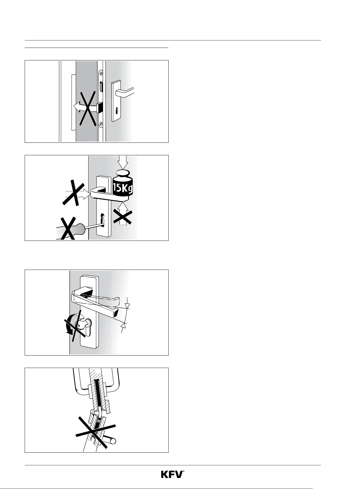
1.4 Improper use................................................. 4
..... 4
....................................................... 5
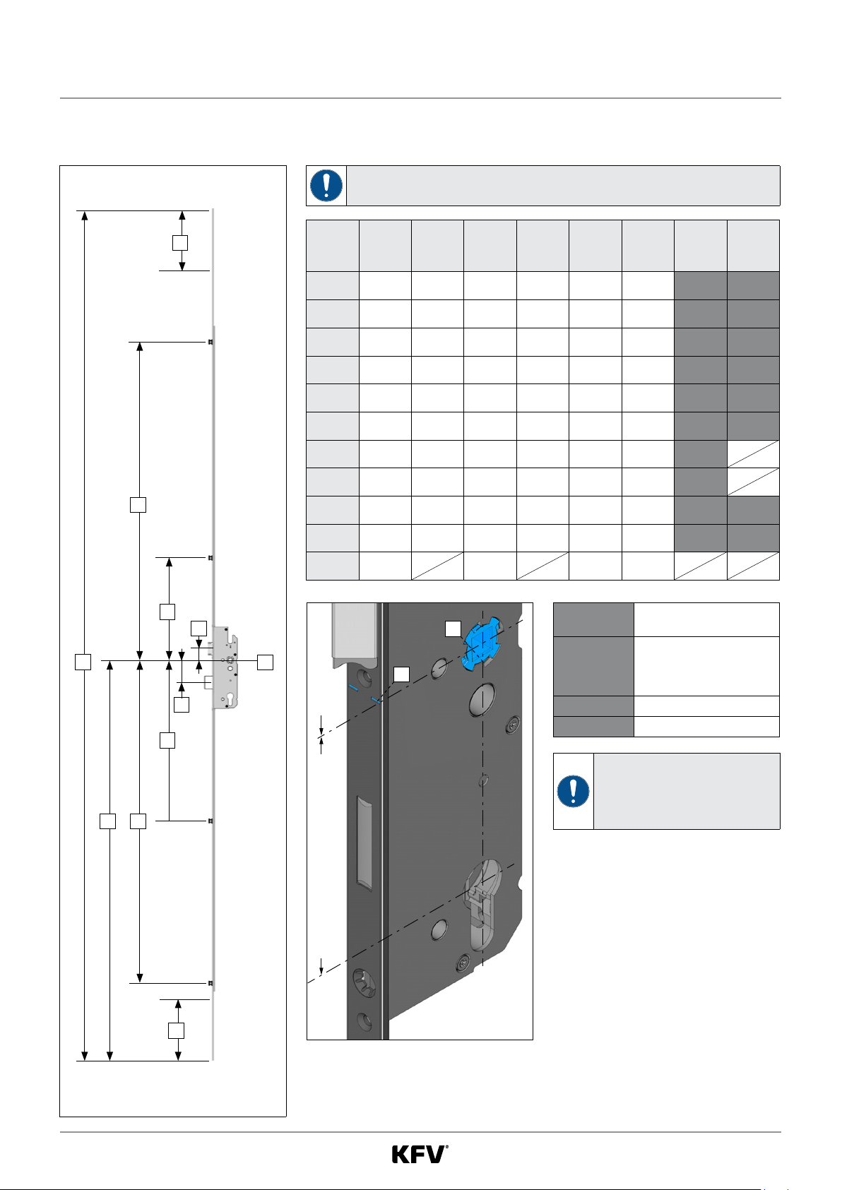
1.7 Dimensions ................................................... 5
................................................ 5
.............................. 6
.............................. 6
................................... 6
..................................... 6
......................................... 6
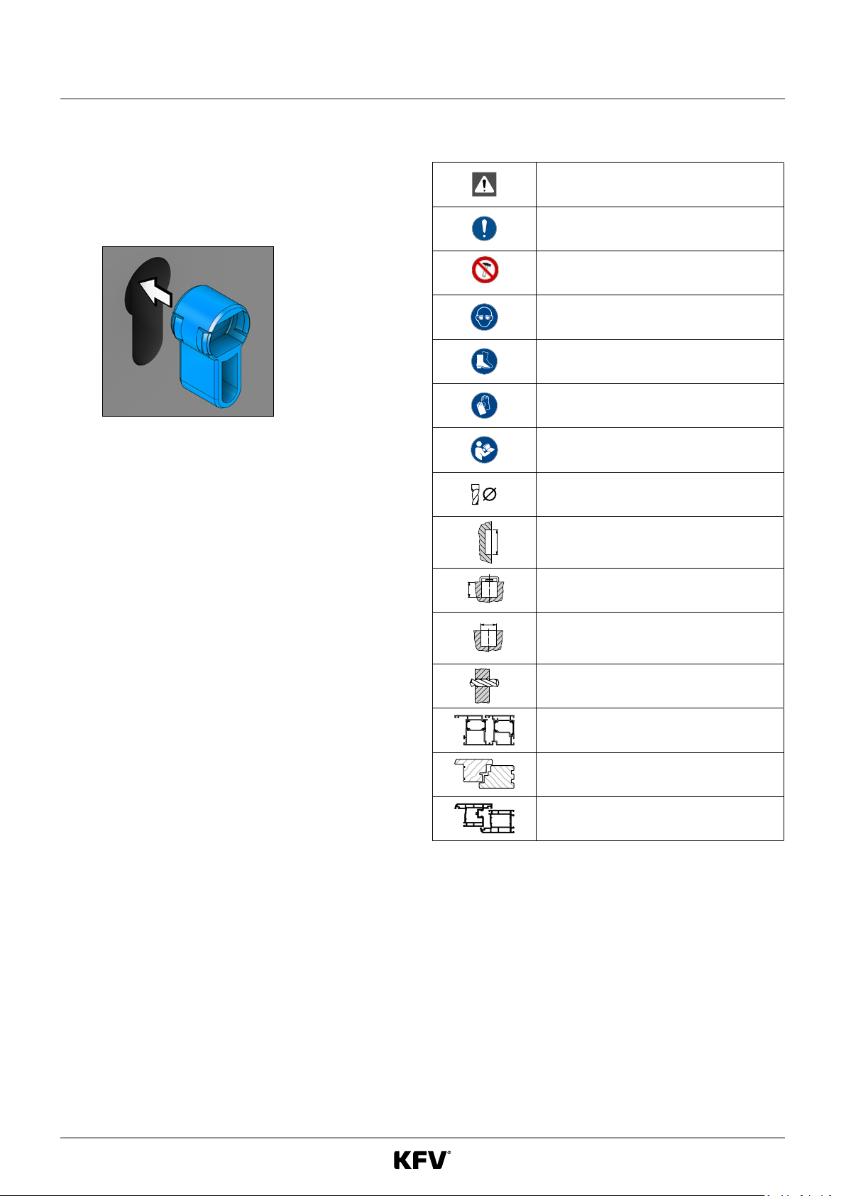
2 SAFETY.......................................................8
.....................
.......................................
...................................................
...........................
3 VARIANTS AND COMPONENTS.................9
................................................ 10
94 mm ......................................................... 10
.......................................... 11
.......................................... 12
.................... 13
........................ 14
4 INSTALLATION .........................................15
.............................................. 15
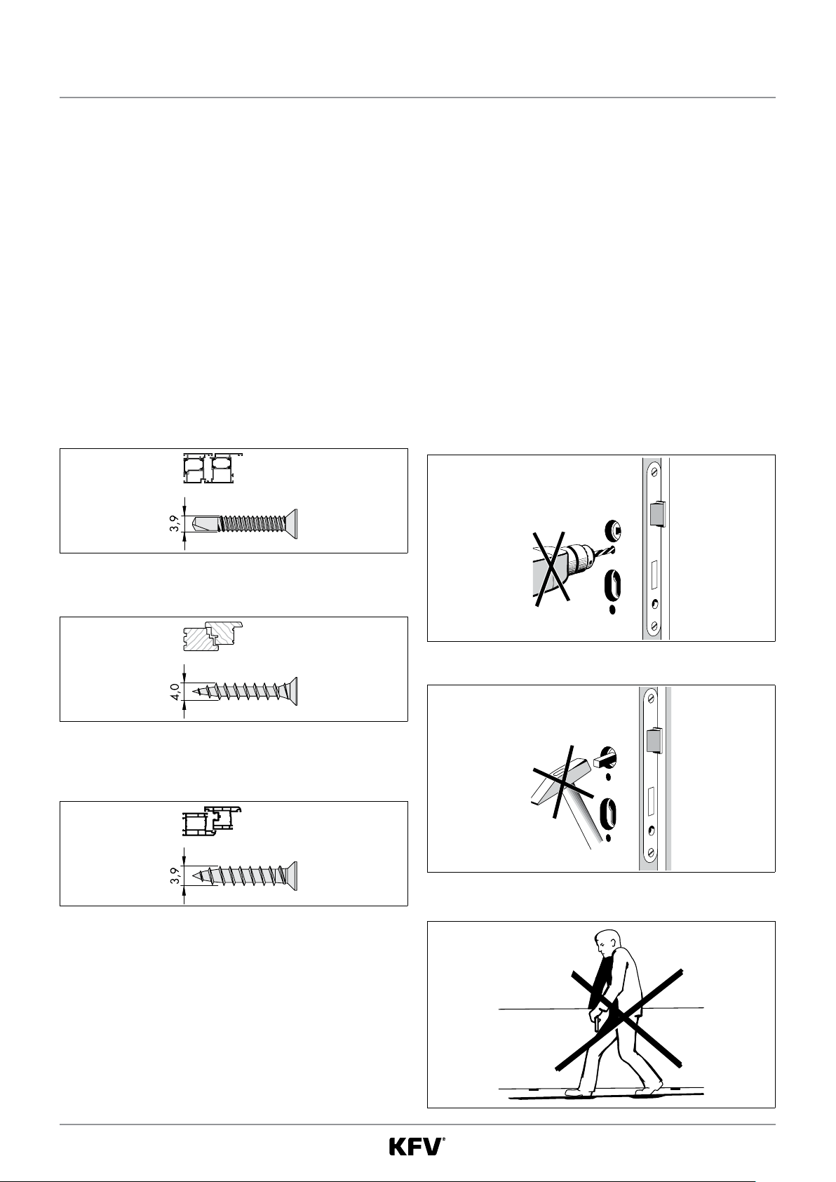
................ 16
........ 17
....................................
..................... 19
................ 20
..................... 21
...................... 22
...... 24
extension piece ........................................... 26
............................. 27
......................................... 29
............. 29
............. 30
.............................. 30
.................... 30
........................ 31
..................................................... 31
..... 32
..... 33
.................................. 34
4.13.1 Adjustment of AT piece............................... 35
4.14 Pressure control .......................................... 37
............................. 37
....................................................
............................................ 39
..................... 39
................... 41
5 TROUBLESHOOTING................................43
...... 43
.................. 43
cylinder ....................................................... 43
.............................. 43

02.20194/44 H39.MFVRS006EN-00
Assembly instrucons
1 Introducon
1.1 Manufacturer and Service
1.2 Target group of this documentaon
1.3 Intended use
1.3.1 Installaon locaon
•
•
•
1.3.2 Locking part and hardware
•
1.4 Improper use
•
doors.
•
•
•
•
•
door open.
•
1.5 Installaon condions and requirements
•
•
•
•
•
•
•
•
•
•

H39.MFVRS006EN-00 02.2019 5/44
Assembly instrucons
1.6 Transport
•
restrictors.
•
•
•
•
1.7 Dimensions
1.8 Symbols used

02.20196/44 H39.MFVRS006EN-00
Assembly instrucons
1.11 Applicable documents
1.12 Appropriate disposal
•
•
1.13 Causes of damage
1.9 Other types of indicators
•
–
f
order.
Cross reference
1.10 Screw recommendaons
Aluminium:
PVC:

H39.MFVRS006EN-00 02.2019 7/44
Assembly instrucons

02.2019/44 H39.MFVRS006EN-00
Assembly instrucons
2 Safety
2.1 Personal protecve equipment
•
•
•
2.2 Heavy components
2.3 Sharp edges
2.4 Swarf ying around rapidly

H39.MFVRS006EN-00 02.2019 9/44
Assembly instrucons
3 Variants and components
BS 2100 BS 2800 A 2100
1 2 3
A 2800
4

02.201910/44 H39.MFVRS006EN-00
Assembly instrucons
3.1 Size variants
3.1.1 PZ dimensions: 72 mm, 74 mm, 92 mm, 94 mm
A
X
C
H
B
F
I
N
M
Size
variants A B C F G H I K
R001 2170 410 1020 260 260 137
R002 2170 770 730 410 1050 260 310 219
R003 2170 660 410 1020 260 410 137
R004 2400 763 737 403 1050 267 534 226
R005 2170 730 410 1049 260 310 110
R014 2170 770 730 410 1020 260 340 189
R016 2170 970 910 410 1042 260 138
R023 2170 970 910 410 1049 260 131
R024 2170 770 410 1042 260 238 212
R025 2170 770 410 1050 260 230 220
K060 660 136 260
Enernung 72, 74, 92, 94 mm
X
1
Dimensions
=
X=
M= 29.0
N= 57.5

H39.MFVRS006EN-00 02.2019 11/44
Assembly instrucons
3.1.2 Distance 85 mm
A
X
C
H
B
F
I
N
M
Size
variants A B C F G H I K
R001 2170 403 1013 267 260 137
R002 2170 763 730 403 1043 267 310 219
R003 2170 660 403 1013 267 410 137
R004 2400 756 737 396 1043 274 534 226
R005 2170 730 403 1042 267 310 110
R014 2170 763 730 403 1013 267 340 189
R016 2170 963 910 403 1035 267 138
R023 2170 963 910 403 1042 267 131
R024 2170 763 403 1035 267 238 212
R025 2170 763 403 1043 267 230 220
K060 660 129 267
Enernung 85 mm -7 mm
X
1
Dimensions
=
X=
M= 36.0
N= 50.5

02.201912/44 H39.MFVRS006EN-00
Assembly instrucons
3.1.3 Distance 88 mm
A
X
C
H
B
F
I
N
M
Size
variants A B C F G H I K
R001 2170 406 1016 264 260 137
R002 2170 766 734 406 1046 264 310 219
R003 2170 664 406 1016 264 410 137
R004 2400 759 741 399 1046 271 534 226
R005 2170 734 406 1045 264 310 110
R014 2170 766 734 406 1016 264 340 189
R016 2170 966 914 406 264 138
R023 2170 966 914 406 1045 264 131
R024 2170 766 406 264 238 212
R025 2170 766 406 1046 264 230 220
664 132 264
Dimensions
=
X=
M= 33.0
N= 53.5
Enernung 88 mm -4 mm
X
1

H39.MFVRS006EN-00 02.2019 13/44
Assembly instrucons
3.1.4 Main lock types, key-operated
Variable dimensions in mm
Main lock type
Cylinder lock
PZ/RZ
PZ
dimension
[E]
Backset
[D]
Rear backset
[L]
Deadbolt
projecon
[R] [M] [N] [O] [P] [Q] [S]
VPZ 72 17.5 20 29 57.5 12.5 51.5 47 12
V RZ 74 17.5 20 29 57.5 12.5 49.5 47 12
HPZ 25 17.5 36 50.5 19.5 31.5 52
HPZ 30 17.5 10 36 50.5 19.5 31.5 52
HPZ 35 17.5 16 36 50.5 19.5 31.5 54 12
HPZ 17.5 20 36 50.5 19.5 31.5 54 12
HPZ 35 17.5 16 33 53.5 16.5 31.5 51 12
HPZ 17.5 20 33 53.5 16.5 31.5 51 12
HPZ 92 25 17.5 29 57.5 12.5 31.5 45
HPZ 92 30 17.5 10 29 57.5 12.5 31.5 45
HPZ 92 35 17.5 16 29 57.5 12.5 31.5 47 12
HPZ 92 17.5 20 29 57.5 12.5 31.5 47 12
H RZ 94 35 20.3 16 29 57.5 12.5 29.5 47 12
H RZ 94 20.3 20 29 57.5 12.5 29.5 47 12
Figure: PZ Figure: RZ
Fräsmaße
D L
R
S
M
E
ON
Q
P
6,5
53,5
3*
System-
markierung
D L
E
P
System

02.201914/44 H39.MFVRS006EN-00
Assembly instrucons
3.1.5 Addional locking elements
BS 2100
9,4
7,3
Ø 7,8
Ø 11
1919
11,5
9,4
1919
BS 2300
19
8
Ø 11

H39.MFVRS006EN-00 02.2019 15/44
Assembly instrucons
4 Installaon
4.1 Change DIN orientaon of the so lock latch
2
11 x 5.5 mm
f
f
f
5x
f
extend completely.

02.201916/44 H39.MFVRS006EN-00
Assembly instrucons
4.2 Swing door roller latch
4.2.1 Replace so lock latch with swing door roller latch
2
1
1 x 5.5 mm
f
f
f
5X
f
completely.

H39.MFVRS006EN-00 02.2019 17/44
Assembly instrucons
4.2.2 Adjustment of swing door roller latch
1
f
2 mm
f
11.9 mm
min.
3.4 mm
34
f
f

02.2019/44 H39.MFVRS006EN-00
Assembly instrucons
4.3 Milling the door leaf
10.
1
2
5
E
3
4
Routed pocket for the main lock
16.0 mm
234.0 mm
137.0 mm
17.5 mm + 1 mm
20.3 mm + 1 mm
Milling for lever handle and
cylinder
21.0 mm
12.0 mm
20.0 mm
E
12 5
6
3
44

H39.MFVRS006EN-00 02.2019 19/44
Assembly instrucons
4.4 Installing the mul-point lock
1
f
f
1
f

02.201920/44 H39.MFVRS006EN-00
Assembly instrucons
4.5 Extension pieces A 2100, A 2800
element.
A 2100 A 2800
Min. 10 mm
195,7 mm
185,7 mm
Max. Kürzbarkeit
298,6 mm
298,6 mm
Min. 10 mm
195,7 mm
185,7 mm
Max. Kürzbarkeit
298,6 mm
298,6 mm
195.7 mm
195.7 mm
This manual suits for next models
1
Table of contents
Other Siegenia Door Lock manuals
Popular Door Lock manuals by other brands

GATEMASTER
GATEMASTER BDG1030 Specification sheet

BQT Solutions
BQT Solutions COBALT-mini YD39M Installation and operating instructions

Kaba Mas
Kaba Mas 3750 User operating instructions

Borglocks
Borglocks BL 2000 quick start guide

Borglocks
Borglocks BL4409 ECP Parts List, Installation and General Information

Borglocks
Borglocks BL5000 ECP quick start guide