manuals.online logo
Brands
  1. Home
  2. •
  3. Brands
  4. •
  5. Assa Abloy
  6. •
  7. Door Lock
  8. •
  9. Assa Abloy Sargent 10X Line User manual

Assa Abloy Sargent 10X Line User manual

A8334 07/22
Installation Instructions
For installation assistance contact SARGENT
1-800-543-3658 • techsupport.sargent@assaabloy.com • www.sargentlock.com
Copyright©2022,ASSAABLOYAccessandEgressHardwareGroup,Inc.Allrightsreserved.
Reproductioninwholeorinpart without the express written permission of ASSAABLOYAccess
andEgressHardwareGroup,Inc.isprohibited.
2
11 3
4
5
6
8
7
9
1
14
12
13 15
10
Installation Instructions
2Product Components
1Tools Required
10XLinewithBHWTrim
Fig. Description
1 Inside escutcheon & lever assembly
2 Outside escutcheon & lever
assembly
3 Inside spring housing assembly
4 Screws - through-bolt (2) #10-32
x 1-1/4"
5 Lockbody assembly with mounting
plate
6 Outside spring housing assembly
7 Cylinder spacer
8 Cylinder
9 Key
10 Latch
11 Screws - latch (2) #8-32 x 3/4"
12 Screws - strike (2) #12-24 x 3/4"
13 Strike
14 Strike box (Optional)
15 Screws- through-bolt (3) #10-24 x
3-1/2"
3Door Preparation
IMPORTANT
• The accuracy of door preparation is critical for proper functioning and security of this lever handle lock. Misalignment can
cause premature wear and a lessening of security.
• Be sure to verify backset before marking and drilling door.
1. Use template A8335 to mark the door (Figure 1).
2. Drill the door according to the template.
3. Verify the dimensions (Figure 2).
4. Install the strike (Figure 3)
DOOR
FRAME
Desired
height
above
floor
Template
Backset must
match latch
Door bevel
2x 7/16" (11mm) hole
1-1/8"
(29mm)
2-1/4"
(57mm)
1" (25mm)
hole
5/32" (4mm)
2-3/4"
(70mm)
Strike Box
Attaching Screws
#12 -24 x 3/4"
3x 1/2" (13mm) hole
4-3/4"
(120mm)
1-11/16"
(43mm)
2-1/8"
(54mm)
hole
5/8"
(16mm)
• 5/32"drillbit • 1/2 "drillbit • 7/16"drillbit • 1/8"drillbit
• #2Phillipsscrewdriver • T25SecurityTorx ® screwdriver • T15SecurityTorx ® screwdriver
10XLinewithBHWTrim
InstallationInstructions
2
Copyright©2022,ASSAABLOYAccessandEgressHardwareGroup,Inc.Allrightsreserved. Reproduction in whole or in
part without the express written permission of ASSAABLOY Access and Egress Hardware Group, Inc. is prohibited.
For installation assistance contact SARGENT
1-800-543-3658 • techsupport.sargent@assaabloy.com • www.sargentlock.com A8334 07/22
Centerline
ofretractor
Retractor
DimensionA
5Door Thickness Adjustment (if necessary)
6Install Outside Lockbody Assembly
To adjustlockto doorthicknessif otherthan 1-3/4"
(44mm)refer toSection5.
Insert lockbodyassembly into doorfromoutside
makingsure thatlockbodyhooks latchcase and
retractorengages bolttail(s). (Figure 7)
DONOTFORCE.(If lockbodydoes not engagelatch
easily,checkdoor preparationfor errors.)
Latch bolttailshould becentered indepthof
retractor.If itis not,refer to Section5 to properly
adjustthe lockfordoor thickness.
Lockis factory presetfor1-3/4"(44mm) doorsunlessspecified. Toadjust lockto
doorthickness ifotherthan 1-3/4"(44mm):
1. Removeoutside spring housingfrom lockbody assembly.
2. Rotate mounting plate to adjust for proper door thickness.
• For 2"thick door the inside face of the mounting plate should be
flush with the face of the bearing. (Figure 5)
• Verify correct position from the markings on the through-bolt
stud, or by measuring from inside surface of the mounting plate to
the centerline of the retractor. (Figure 6)
3. Reassemble outside
springhousing onto
lockbodyassembly.
Door Thickness Dimension A
1-3/4"(44 mm) 7/8" (22mm)
2"(50 mm) 1" (25mm)
4Latch Installation
Insert latchin door. (Besure bevel edgeof bolt facesstrike plate.)
Attach with(2) #8-32x 3/4"screwssupplied.
Strike
Important: Deadlockinglatch must stopon strike whendoor is closed.
Bearing
These
surfaces
flush
MountingPlate
Figure 6Figure 5
10XLinewithBHWTrim
InstallationInstructions
3
Copyright©2022,ASSAABLOYAccessandEgressHardwareGroup,Inc.Allrightsreserved. Reproduction in whole or in
part without the express written permission of ASSAABLOY Access and Egress Hardware Group, Inc. is prohibited.
For installation assistance contact SARGENT
1-800-543-3658 • techsupport.sargent@assaabloy.com • www.sargentlock.com A8334 07/22
7Cylinder Installation
IMPORTANT
Before installing cylinders:
• Use a flat blade screwdriver to rotate cam until the driver points
are in a 6 and 12 o’clock position. (Figure 8A)
Cylinder spacer should be installed “snapped”on to the cylinder
before installing into the outside trim assembly.
1. Install cylinder into the lever. (Figure 8B)
• Removetemporary construction coreor plasticcore. Ifkeyed, use
ControlKey.Rotate15° andpull.
• Insert permanentcoreinto lever withcontrol key. Rotate15° and
removekey.
a StandardCylinder(Figure8)
b InterchangeableorRemovableCore(Figure9)
Key
BHW Trim
Cylinder
Cylinder Spacer
Figure 8B
C
C
New Core
Figure 9
Viewintolockfrom
endoftrim
12o’clockdrivepoint
6o’clockdrivepoint
Figure 8A
IMPORTANT
• Remove tailpiece from construction core and insert into new core. If using 7 pin cores,
insert the 7 pin tail piece that’s supplied with the lock, before installing the core into the
lock.
• For XC LFIC cores, snap-on retainer must be installed onto tailpiece. Tail and retainer
assembly will press fit onto back of core. XC LFIC
For installation assistance contact SARGENT
1-800-543-3658 • techsupport.sargent@assaabloy.com • www.sargentlock.com
Copyright©2022,ASSAABLOYAccessandEgressHardwareGroup,Inc.Allrightsreserved.
Reproductioninwholeorinpart without the express written permission of ASSAABLOY Access
andEgressHardwareGroup,Inc.isprohibited.
WARNING
Thisproduct canexpose youto lead
whichis knownto thestate of California
tocause cancerand birth defects orother
reproductiveharm. Formore informationgo
towww.P65warnings.ca.gov.
10XLinewithBHWTrim
InstallationInstructions
A8334 07/22
Competitor’s
Cylinder
Cap Pin
End Cap
9Cylinder Options
1. Providedless cylinder.
2. Depresscap pinandunscrew endcap to removetailpiece from
competitor’scylinder.(Figure 11)
3. Insert newtailpiece inorientation shown.
4. Reassembleend capovernew tailpiece.
a LevertoAcceptSchlage®orYale®FixedCoreCylinder(30-orYC- Option)
8Install Inside and Outside Escutcheon & Lever Assemblies
1. Alignand insert inside springhousing onto theinstalled lockbody.
2. Install (2) #10-32x 1-1/4” screwsto tighten thespring housing tothe door.
3. Mountinside escutcheonand leverassembly over theinside spring housing.
4. Mountoutsideescutcheon andlever assemblyover theoutside springhousing.
5. Securethe assembliesusingthe (3)screws #10-24 x3-1/2"(Figure 10)
Screws (2) #10-32 x 1-1/4"
Screws (3) #10-24 x 3-1/2"
Figure 10
Figure 11

Other Assa Abloy Door Lock manuals

Assa Abloy Sargent 8200 Series User manual

Assa Abloy

Assa Abloy Sargent 8200 Series User manual

Assa Abloy Yale Assure Technical specifications

Assa Abloy

Assa Abloy Yale Assure Technical specifications

Assa Abloy 1125 Series User guide

Assa Abloy

Assa Abloy 1125 Series User guide

Assa Abloy Corbin Russwin Access 700 ML20700 TCPWI1... User manual

Assa Abloy

Assa Abloy Corbin Russwin Access 700 ML20700 TCPWI1... User manual

Assa Abloy Yale PAS3621 User manual

Assa Abloy

Assa Abloy Yale PAS3621 User manual

Assa Abloy Yale YDME 50 NxT User manual

Assa Abloy

Assa Abloy Yale YDME 50 NxT User manual

Assa Abloy OneSystem type A Guide

Assa Abloy

Assa Abloy OneSystem type A Guide

Assa Abloy Sargent PE8800 Series User manual

Assa Abloy

Assa Abloy Sargent PE8800 Series User manual

Assa Abloy PEMKO LP200 Series User manual

Assa Abloy

Assa Abloy PEMKO LP200 Series User manual

Assa Abloy Yale 6100 User manual

Assa Abloy

Assa Abloy Yale 6100 User manual

Assa Abloy RIXSON W73 User manual

Assa Abloy

Assa Abloy RIXSON W73 User manual

Assa Abloy Corbin Russwin Access 800 Series User manual

Assa Abloy

Assa Abloy Corbin Russwin Access 800 Series User manual

Assa Abloy Corbin Russwin ED5800 Series User manual

Assa Abloy

Assa Abloy Corbin Russwin ED5800 Series User manual

Assa Abloy NORTON RIXSON M19 User manual

Assa Abloy

Assa Abloy NORTON RIXSON M19 User manual

Assa Abloy besam US23-0696-01 Programming manual

Assa Abloy

Assa Abloy besam US23-0696-01 Programming manual

Assa Abloy Yale Doorman User manual

Assa Abloy

Assa Abloy Yale Doorman User manual

Assa Abloy Pyramid User manual

Assa Abloy

Assa Abloy Pyramid User manual

Assa Abloy Sargent FM-PE8700 Series User manual

Assa Abloy

Assa Abloy Sargent FM-PE8700 Series User manual

Assa Abloy Yale Doorman User manual

Assa Abloy

Assa Abloy Yale Doorman User manual

Assa Abloy Yale YDLL/BLK Troubleshooting guide

Assa Abloy

Assa Abloy Yale YDLL/BLK Troubleshooting guide

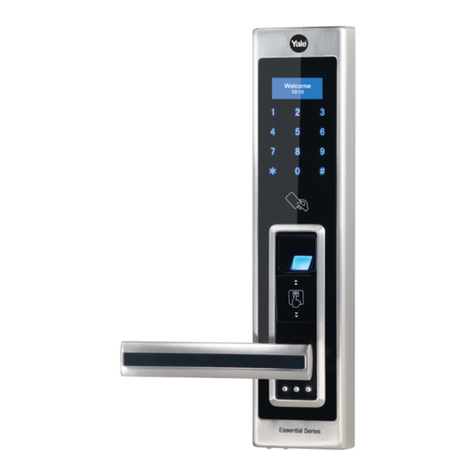
Assa Abloy Yale Essential Series User manual
Assa Abloy

Assa Abloy Yale Essential Series User manual

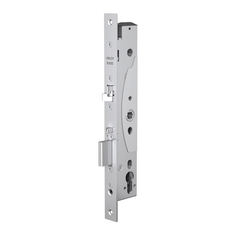
Assa Abloy EL580 User manual

Assa Abloy

Assa Abloy EL580 User manual

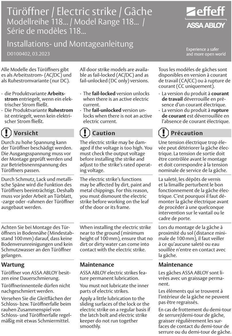
Assa Abloy Effeff EX118P Series User manual

Assa Abloy

Assa Abloy Effeff EX118P Series User manual

Assa Abloy effeff ANYKEY User manual

Assa Abloy

Assa Abloy effeff ANYKEY User manual

Popular Door Lock manuals by other brands

CODELOCKS CL5510 installation guide

CODELOCKS

CODELOCKS CL5510 installation guide

Kaba PowerLever 455 Series operating instructions

Kaba

Kaba PowerLever 455 Series operating instructions

SECO-LARM SD-993C-D3Q manual

SECO-LARM

SECO-LARM SD-993C-D3Q manual

Samsung SHS-1321 instruction manual

Samsung

Samsung SHS-1321 instruction manual

Simpled BF-SPS user manual

Simpled

Simpled BF-SPS user manual

CODELOCKS CL5000 Programming and operating instructions

CODELOCKS

CODELOCKS CL5000 Programming and operating instructions

Salto Neo S3 Series installation guide

Salto

Salto Neo S3 Series installation guide

Emtek EMTouch Installation & programming guide

Emtek

Emtek EMTouch Installation & programming guide

Longleaf Collection 20 FUNCTION installation instructions

Longleaf Collection

Longleaf Collection 20 FUNCTION installation instructions

Salto Neo RIM N B1 1 Series installation guide

Salto

Salto Neo RIM N B1 1 Series installation guide

PERCo LB-85.3 Operation manual

PERCo

PERCo LB-85.3 Operation manual

Salto AF i 2 Series installation guide

Salto

Salto AF i 2 Series installation guide

Philio Technology Corporation PSA03 manual

Philio Technology Corporation

Philio Technology Corporation PSA03 manual

Weiser PowerboIt 3 Installation and user guide

Weiser

Weiser PowerboIt 3 Installation and user guide

Esco systeQ-M-SLM-ESC quick start guide

Esco

Esco systeQ-M-SLM-ESC quick start guide

Kaba PowerLever 15 Series operating instructions

Kaba

Kaba PowerLever 15 Series operating instructions

Yale Helios S user guide

Yale

Yale Helios S user guide

Ezset PL1 user manual

Ezset

Ezset PL1 user manual

manuals.online logo
manuals.online logoBrands
  • About & Mission
  • Contact us
  • Privacy Policy
  • Terms and Conditions

Copyright 2025 Manuals.Online. All Rights Reserved.