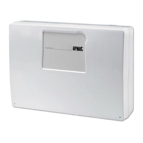
urmet domus 1061/006A Assembly instructions

DS1061-036A LBT20130
MULTIFUNCTION CONTROL PANEL
Ref.1061/006A
INSTALLATION AND PROGRAMMING MANUAL
Mod.
1061

2 DS1061-036A
TABLE OF CONTENTS
1GENERAL DESCRIPTION.................................................................................................................... 6
1.1 SYSTEM ARCHITECTURE ......................................................................................................... 6
1.2 SYSTEM DESCRIPTION AND ITS EXPANSIONS ..................................................................... 6
1.3 SYSTEM COMPONENTS ............................................................................................................ 7
1.3.1 1061/006A Control panel .........................................................................................................7
1.3.2 Management keypad with Led – 1061/025 .............................................................................. 8
1.3.3 Electronic key reader – 1061/334 and 1061/335 ..................................................................... 8
1.3.4 Proximity reader – 1061/434 and 1061/435............................................................................. 8
1.3.5 Electronic key – 1061/332........................................................................................................ 9
1.3.6 Transponder key – 1056/032 ................................................................................................... 9
1.3.7 PSTN telephone communicator – 1061/002 ............................................................................ 9
1.3.8 GSM module – 1061/458 ......................................................................................................... 9
1.3.9 Speech synthesis board – 1061/012........................................................................................ 9
1.3.10 Informative and environmental module – 1061/013 ............................................................ 10
1.3.11 USB 2.0 interface – 1061/003 ............................................................................................. 10
1.3.12 Software for programming and remote assistance – 1061/001 .......................................... 10
1.3.13 Residential series adapters................................................................................................. 11
2SYSTEM DESIGN ............................................................................................................................... 12
2.1 NOTES FOR A CORRECT INSTALLATION.............................................................................. 12
2.2 BATTERY DIMENSIONING ....................................................................................................... 12
2.3 CALCULATION OF THE TOTAL ABSORPTION OF THE SYSTEM......................................... 12
2.4 CABLE DIMENSIONING AND POSITIONING........................................................................... 13
2.4.1 Dimensioning ......................................................................................................................... 13
2.4.2 Data bus cable ....................................................................................................................... 14
2.4.3 Audio cable ............................................................................................................................ 14
2.4.4 Coexistence with mains cables.............................................................................................. 14
3INSTALLATION ................................................................................................................................... 15
3.1 CONTROL PANEL ..................................................................................................................... 15
3.1.1 Fixing ..................................................................................................................................... 15
3.1.2 Control panel options addition ............................................................................................... 18
3.2 ELECTRONIC KEY READER AND PROXIMITY READER....................................................... 22
3.3 MANAGEMENT KEYPAD .......................................................................................................... 23
4CONNECTIONS .................................................................................................................................. 25
4.1 BUS DEVICES CONNECTION .................................................................................................. 25
4.2 CONTROL PANEL ..................................................................................................................... 26
4.2.1 Motherboard........................................................................................................................... 26
4.2.2 Inputs connection and configuration ...................................................................................... 28
4.2.3 Outputs connection ................................................................................................................ 29
4.2.4 Selecting the control panel operating mode........................................................................... 30
4.3 KEYPAD ..................................................................................................................................... 31
4.3.1 Auxiliary input......................................................................................................................... 31
4.3.2 Tamper input.......................................................................................................................... 31
4.4 MAINS AND BATTERY CONNECTIONS .................................................................................. 32
5PROGRAMMING................................................................................................................................. 33
5.1 PROGRAMMING PROCEDURE ............................................................................................... 33
5.2 CONTROL PANEL HARDWARE PROGRAMMING INTERFACE............................................. 33

DS1061-036A 3
5.3 FIRST POWER-UP .................................................................................................................... 34
5.4 SYSTEM CONFIGURATION VIA HARDWARE......................................................................... 34
5.4.1 Entering in programming mode.............................................................................................. 34
5.4.2 Main programming menu ....................................................................................................... 35
5.4.3 Inputs programming menu ..................................................................................................... 36
5.4.4 Outputs Programming Menu.................................................................................................. 37
5.4.5 Zones programming menu..................................................................................................... 38
5.4.6 Times programming menu ..................................................................................................... 39
5.4.7 Keys programming menu....................................................................................................... 41
5.4.8 Codes programming menu .................................................................................................... 42
5.4.9 Keys / zones association menu ............................................................................................. 42
5.4.10 Codes / zones association menu ........................................................................................ 43
5.4.11 PSTN/GSM communicator programming menu.................................................................. 44
5.4.12 Vocal messages recording menu........................................................................................ 47
5.4.13 Keypad auxiliary inputs programming ................................................................................. 49
5.4.14 Exit from programming procedure....................................................................................... 49
5.5 SYSTEM CONFIGURATION VIA SOFTWARE ......................................................................... 50
5.5.1 USB interface mounting and pc connection........................................................................... 50
5.5.2 Basic parameters programming............................................................................................. 51
5.5.3 Telephone communicators configuration ............................................................................... 53
6FINAL OPERATIONS.......................................................................................................................... 55
6.1 COMPLETION............................................................................................................................ 55
6.1.1 Electronic key/proximity readers closing................................................................................ 55
6.1.2 Keypads closing..................................................................................................................... 55
6.1.3 Control panel closing ............................................................................................................. 55
6.2 TEST .......................................................................................................................................... 55
7MAINTENANCE .................................................................................................................................. 55
7.1 MAINTENANCE PROCEDURE ................................................................................................. 55
7.2 READER..................................................................................................................................... 56
7.2.1 Electronic key/proximity reader addition ................................................................................ 56
7.2.2 Electronic key/proximity reader deleting ................................................................................ 56
7.2.3 Electronic key/proximity reader replacement ......................................................................... 56
7.3 KEYPAD ..................................................................................................................................... 57
7.3.1 Keypad addition ..................................................................................................................... 57
7.3.2 Keypad deleting ..................................................................................................................... 57
7.3.3 Keypad replacement ..............................................................................................................57
7.4 DETECTOR................................................................................................................................ 58
7.4.1 Detector addition.................................................................................................................... 58
7.4.2 Detector deleting.................................................................................................................... 58
7.4.3 Detector replacement............................................................................................................. 58
7.5 ADDITION OF A CONTROL PANEL OPTIONAL DEVICE ........................................................ 58
7.6 BATTERY REPLACEMENT ....................................................................................................... 59
7.7 CLEANING ................................................................................................................................. 59
8TECHNICAL CHARACTERISTICS ..................................................................................................... 60
8.1 1061/006A CONTROL PANEL................................................................................................... 60
8.2 1061/025 MANAGEMENT KEYPAD .......................................................................................... 61
8.3 ELECTRONIC KEY READER .................................................................................................... 61
8.4 PROXIMITY READER................................................................................................................61
8.5 1061/002 PSTN TELEPHONE COMMUNICATOR .................................................................... 61
8.6 1061/458 GSM MODULE........................................................................................................... 62
4 DS1061-036A
8.7 1061/012 SPEECH SYNTHESIS BOARD ................................................................................. 62
8.8 1061/013 ENVRONMENTAL LISTENING MODULE/MESSAGES REPEATER ....................... 62
9EXAMPLE OF CONNECTION WITH NC LINES................................................................................. 63
10 FACTORY SETTINGS ........................................................................................................................ 65
ANNEX – SYSTEM FINAL CONFIGURATION............................................................................................ 66

DS1061-036A 5
WARNING!
The operating mode this manual explains is compliant with
the requests provided in EN50131 standard.
In order to enable this operating mode, the yellow jumper
JP4 must be open (see figure 22).
Please see paragraph 4.2.4 Selecting the control panel
operating mode for more details.
Closed JP4
This operating mode is compliant with
EN50131 standard Grade 1, please see the
relevant manual.
Open JP4
This operating mode is NOT compliant with
EN50131 standard, which is explained in this
manual.

6 DS1061-036A
1 GENERAL DESCRIPTION
The 1061 burglar system has been designed and developed for small-sized systems, used for example in
residential areas and little companies (offices, shops, workshops and little factories) and can be easily
adapted for different requirements.
Maximum compactness, flexibility and safety are the system main characteristics; its installation, use and
programming procedures are user-friendly for both installer and users.
1.1 SYSTEM ARCHITECTURE
The system 1061 is equipped with 6 inputs, 4 outputs, and 4 zones.
The following functions are allowed:
•Communication on BUS line.
•Up to 4 zones, that can be freely associated and partially armed.
•Activation by keypads with code, electronic key or proximity key.
•User-friendly interface.
•Voice and digital communicators used for alarm information sending both to users and alarm
reception centres.
•Capability to manage Anti-theft, Emergency and Technological functions.
•Local and remote system programming and check, by PC.
•Capability to check the system state also with DTMF.
1.2 SYSTEM DESCRIPTION AND ITS EXPANSIONS

DS1061-036A 7
1.3 SYSTEM COMPONENTS
1.3.1 1061/006A Control panel
The control panel 1061/006A manages the whole system by means of a microprocessor. Its features and
performance are as follows:
No. of Zones for free
partial arming
No. of inputs for alarm detectors
(lines) Alarm outputs no.
4 6 2 clean relay outputs
1 output for internal siren
1 output for self-powered external siren
•220 ÷ 240V~, 50/60 Hz power supply, with 12 V backup battery.
•Inputs configurable as balanced or fast (to connect directly the rolling shutter contact)
•Up to 8 command devices, that can be freely chosen between electronic key or transponder key
readers (4 max) and keypads (4 max).
•1 24H input (always active).
•Up to 10 keys
•Up to 10 codes, freely programmable (from 4 to 6 digits).
•Free association of inputs to zones
•Anti-theft function (with keypad only).
•Technological input for technological detectors (smoke, fire, flood, etc.).
•“Technological” alarm management (dedicated output in case of “technological alarm”).
•“Emergency” alarm management.
•Freely selectable entry and exit times.
•1 delayed input.
•LED on the control panel front side to display state/occurred events.
•Capability to exclude each input by dedicated buttons on the control panel front.
•Input automatic exclusion after 8 consecutive alarms.
•Automatic exclusion of the open input at the activation time (function selectable by jumper).
•Alarm events log (browsable with PC)
•RS232-USB interface (optional).
•Local or remote control panel programming by PC with application software.
•PSTN telephone communicator (optional).
•GSM module (optional).
•Priority selection between PSTN/GSM, if in the control panel are installed both the modules.
•Remote management (system state inquiry, with DTMF commands or PC and system activation with
DTMF commands).
•Remote assistance (system parameters configuration and change).
•Remote surveillance (alarm and signalling sending with numeric protocols: IDP – ADF – SIA).

8 DS1061-036A
1.3.2 Management keypad with Led – 1061/025
The management keypad with LEDs allows to arm and disarm the system, also partially, by signalling the
zones state on dedicated LEDs, with alarms storage and failures signalling.
The keypad manages up to 10 codes (from 4 to 6 digits) and is equipped with an internal buzzer, auxiliary
input and tamper input. By entering on the keypad a special code (programmable), can be activated the
anti-theft function.
The keypad is connected to the control panel with the 4-wire bus and can be wall mounted, with the
provided box, or flush mounted on 3-modules box, using in both the cases the Simon Urmet Nea residential
series frame and plate, provided with product.
1.3.3 Electronic key reader – 1061/334 and 1061/335
The reader allows to arm and disarm the system, also partially, with an electronic key; it is connected to the
control panel with the 4-wire bus. A Simon Urmet series Nea adapter is provided with the key.
1.3.4 Proximity reader – 1061/434 and 1061/435
The proximity reader allows to arm and disarm the system, also partially, with a transponder key; it is
connected to the control panel with the 4-wire bus. A Simon Urmet series Nea adapter is provided with the
reader.

DS1061-036A 9
1.3.5 Electronic key – 1061/332
Programmable electronic key, to be used with the electronic key reader.
1.3.6 Transponder key – 1056/032
Programmable transponder key, to be used with the proximity reader.
1.3.7 PSTN telephone communicator – 1061/002
The PSTN telephone communicator can be programmed with the control panel function keys or with PC
and allows to:
•Send, with an encoded digital link, the information concerning alarms and system state to the
dedicated alarm reception centres.
•Send, paired with the speech synthesis card, vocal messages by telephone calls.
•Perform a remote check of the system, by DTMF commands.
•Perform a remote management of the system and check its operations by a dedicated application
software.
•Environmental listening (paired with 1061/013).
1.3.8 GSM module – 1061/458
The GSM Dual Band module can be programmed with the control panel function keys or with PC; it allows to:
•Send, paired with the speech synthesis card, vocal alarm messages and SMS.
•Perform a remote check of the system, by DTMF commands.
The antenna is provided with the product.
1.3.9 Speech synthesis board – 1061/012
The speech synthesis board, paired with the PSTN telephone communicator or the GSM module, allows
the alarm message recording.

10 DS1061-036A
1.3.10 Informative and environmental module – 1061/013
The informative and environmental listening module allows the environmental listening by a telephone call
(the control panel must be provided with a PSTN telephone communicator) and the local playback of
messages concerning system state, alarm, failure.
1.3.11 USB 2.0 interface – 1061/003
The USB 2.0 interface allows to connect a PC to the 1061/006A control panels for their programming (the
programming and remote assistance software is needed).
1.3.12 Software for programming and remote assistance – 1061/001
The programming and remote assistance software allows to program with a PC the 1061/006A control
panel (USB 2.0 interface is needed). The same software allows to perform remote assistance services on
control panels equipped with PSTN telephone communicator.

DS1061-036A 11
1.3.13 Residential series adapters
To adapt the readers on the most common residential series, are used the suitable adapters provided in
the kit for 1056, 1061 and 1063 series (product code: 1056/337). The kit is composed by: 1 BTicino Living
International adapter, 1 BTicino Living adapter, 1 Vimar Plana adapter, 1 Vimar Idea adapter, 1 Gewiss
Playbus adapter.

12 DS1061-036A
2 SYSTEM DESIGN
2.1 NOTES FOR A CORRECT INSTALLATION
The 1061/006A control panel must be placed in a position protected by burglar detectors. If it is needed the
GSM module usage, it is necessary to verify in advance if, in the selected position, the GSM signal is good.
To check it, verify the field strength using the GSM coverage test (see paragraph 5.4.11).
WARNING:For GSM network coverage check, it is necessary to use the same mobile network carrier
SIM as the one used in the GSM module. This because in the same place, coverage levels of various
mobile network carriers can be very different, or even absent.
Management keypads, electronic key readers and proximity readers must be put in dry places, protected
against bad weather conditions. These devices are daisy chained to the control panel with a single bus
cable. The sequence used to connect them to the bus is irrelevant (devices are identified by a hardware
address, not according to the connection sequence), so it is possible to use for the bus the most
convenient and the fastest path for installation.
2.2 BATTERY DIMENSIONING
The system must be sized so as to guarantee, in case of a blackout, a minimum time of autonomy (it is
suggested at least 12 hours).
Therefore, in order to guarantee minimum duration of the battery, the system powered directly by the
control panel must comply with the following requirements.
1061/006A control panel with 7.2 Ah battery.
Absorption allowed
Autonomy Control panel*All the devices powered by the control panel Total
12 hours 60 mA 390 mA 450 mA
24 hours 60 mA 170 mA 230 mA
*Control panel without communicators and interfaces.
WARNING:Use batteries with UL 94 HB class inflammability or better.
2.3 CALCULATION OF THE TOTAL ABSORPTION OF THE SYSTEM
In order to calculate the total system absorption, proceed as follows:
•list all the necessary devices, with their quantity and maximum absorption per unit in stand-by (which
is all available from the technical specifications);
•multiply the quantity and the absorption in order to get the subtotal for each device;
•sum all the partial totals to obtain the subtotal;
•add 10% to the subtotal for potential future upgrades;
•calculate the total.

DS1061-036A 13
The table below illustrates an example of how to calculate the total absorption:
Device Quantity Max absorption: Total
Control panel 1 X 60 mA = 60 mA
PSTN Communicator 10 mA = … mA
GSM Module 30 mA = … mA
Speech synthesis 30 mA = … mA
Keypads ….. … X … mA = … mA
Readers … X … mA = … mA
Expansion modules … X … mA = … mA
IR detectors … X … mA = … mA
SUBTOTAL … mA
+ 10% for future upgrades … mA
TOTAL … mA
Note: ▪Magnetic contacts do not absorb electricity.
▪The self-powered siren, when it sounds, draws electricity from its own battery.
WARNING! To not overload the control panel battery, when the mains power supply is absent,
plan to use the self-powered sirens and optical signals (equipped with their own battery).
2.4 CABLE DIMENSIONING AND POSITIONING
2.4.1 Dimensioning
The cable cross section must be calculated considering the most critical system power supply condition,
equivalent to mains fail and backup battery just over the “flat battery” level (11.2 Vdc).
For example, if at full load conditions, on all the devices power supply terminals must be ensured at least
10.5 Vdc, the maximum voltage dropout admitted on the cables is 0.7 Vdc.
The calculation formula is:
Vc= 2 x length x Rmx Id
where:
Vcis the voltage dropout in Volt
length is the cable length, in metres (single wire)
Rmis the cable resistance in Ohm/m
Id is the current required by the devices, in Ampere (value obtained by their technical sheets)
The values of copper cable resistance are:
Cross section – mm20.22 0.50 0.75 1.00 1.50
Resistance – Ohm/m 0.0795 0.0350 0.0233 0.0175 0.0117

14 DS1061-036A
The following diagram can be useful to find the minimum cable section that is necessary.
WARNING: The diagram is used for a preliminary estimation; for an accurate calculation, use the
formula described above. However, it is necessary to verify with a voltmeter, that the voltage measured on
terminals of each device is not lower than the power supply voltage provided by the control panel or by the
additional power supply unit (0.7 Vdc).
Using an alarm system cable with a section of 0.22mm2for the serial line (LA LB) and 0.5mm2for power
supply (+, –), the maximum distance of peripherals is:
•1061/334-/335 readers: 200 m
•1061/434-/435 readers: 100 m
•1061/025 keypad: 50 m
2.4.2 Data bus cable
For the bus is needed a 4-wire cable, and it is suggested to use a shielded cable for alarm system 4 x 0.22 mm2 +
2 x 0.5 mm2, in order to have available the wire pair for readers tampers contacts.
Bus maximum length can not exceed 500 m.
2.4.3 Audio cable
For the audio line, use a twisted pair. The audio line length can not exceed 100 m.
2.4.4 Coexistence with mains cables
Bus cable, audio bus and detectors cables can not be laid in conduits or tubes used for mains cables.

DS1061-036A 15
3 INSTALLATION
3.1 CONTROL PANEL
3.1.1 Fixing
Control panel opening
Open the control panel by unscrewing the screws using a Phillips screwdriver (PH0), the two flush mount
fixing screws, by sliding up the lid, in order to release the ledges (Figure 1).
Figure 1 – Control panel opening

16 DS1061-036A
Opening holes for cables and holes for battery anchoring
On the control panel bottom, open the pre-fractured apertures for cables (power supply, detectors, sirens,
bus, telephone line, audio line and for battery anchoring). Cable number and kinds depend on the system
to be realized.
Figure 2 – Pre-fractured apertures for cable
WARNING: When opening the pre-fractured apertures, take care not to damage the motherboard. For
safety’s sake, it is suggested to remove the motherboard before opening apertures, as shown in the
paragraph Motherboard removal.
C D
D
B
D
C D
B
C D
A
D
A
E
A
D
C
A
E
A - Aperture for flush mount tube
B -Aperture for flush mount tube (electric power supply)
C - Aperture for external tube
D - Aperture for cable trunking
E- Plastic strap slot for battery anchoring

DS1061-036A 17
WARNING: Battery must be anchored by using the provided plastic strap as in figure 3.
Figure 3 – Battery anchoring by using the plastic strap
Wall mounting
The control panel must be placed in an interior, in a zone protected by the alarm system, on a dry, level
wall. The control panel is provided with 4 fixing holes (A and B), accessible without removing the
motherboard.
Figure 4 – Control panel fixing holes
To fix the control panel follow the instructions below:
1. Place the control panel and mark the drilling point for the slot A.
2. Drill the wall, put a screw anchor and screw in its screw; it must stick out about 1cm.
3. Hang the control panel on the screw, place the control panel in horizontal position and mark the drilling
point for slots B.
4. Remove the control panel, drill and put the remaining anchor screws.
5. Hang again the control panel and fix it with the screws, tightening also the screw of hole A. Slots B
allows to compensate hole misalignments, if present, in order to fix the control panel perfectly
horizontal.
A
B B
B

18 DS1061-036A
Protection from tampering and removal
To guarantee the 1061/006A control panels protection from tampering and removal, it is necessary to use
hole Cfor fastening as well.
Figure 5 – Protection from tampering and removal
3.1.2 Control panel options addition
The optional expansion modules are connected on the lower side of the motherboard, that can be removed
from the control panel before any operations.
Note: All the operations performed with open control panel must be done by a skilled technical staff and
after the whole system has been unpowered.
Motherboard removal
To remove the motherboard, unscrew the 6 screws shown in the figure.
Figure 6 – Motherboard fixing screws
To put again the motherboard in the control panel, place it again on its supports and screw in the fixing
screws, without forcing, in order not to damage the printed circuit.
C

DS1061-036A 19
Position and use of expansion connectors for optional boards
The expansion connectors available on the rear of the motherboard are the following:
Figure 7 – Connectors for expansions in motherboard
A - CON3 connector used for connection of 1061/002 PSTN module
B - CON2 connector used for connection of 1061/458 GSM module
C - CON7 connector used for connection of 1061/012 speech synthesis module
PSTN telephone communicator
To add the PSTN telephone communicator, follow the instructions below:
1. Remove, if necessary, the motherboard.
2. Press the 4 nylon pivot pins in the holes placed in the corners of the PSTN telephone communicator.
Support pivot pins must be placed at the rear of the module (the side without electronic components
and connection terminal pins).
3. Put the PSTN telephone communicator on the motherboard (see figure 7 to identify the connector
position).
4. Connect the PSTN telephone communicator to the telephone line, according to the following diagram.
Figure 8 – Connection diagram to the telephone line
For the connection, use a twisted pair; no polarity must be respected.
WARNING: The PSTN telephone communicator must be the first connected device, in order to seize
the line in case of an alarm.
C
B
A

20 DS1061-036A
5. Connect the audio line (microphone), if present, to the MIC terminal pin of the PSTN telephone
communicator, respecting polarities. For the audio line, use a twisted pair. Audio line must not exceed
100m. The following diagram shows how to connect the PSTN telephone communicator and the
module for environmental listening/message repeater.
Figure 9 – Connection diagram for environmental listening
GSM module
To add the GSM module, follow the instructions below:
1. Remove, if necessary, the motherboard.
2. Press the 4 nylon pivot pins in the holes placed in the corners of the GSM module. The support pivot
pins must be placed at the rear of the module (the side without electronic components and antenna
connector).
3. Put the GSM module on the motherboard (see figure 7 to identify the position of the connector).
4. Put the antenna in the two housing slides present on the control panel side (to make the activation
easier, blend lightly the antenna).
Figure 10 – GSM antenna mounting
Table of contents
Other urmet domus Control Panel manuals

urmet domus
urmet domus 925 User manual

urmet domus
urmet domus 2VOICE MIKRA2 1784 Quick start guide

urmet domus
urmet domus 1061/004 Assembly instructions

urmet domus
urmet domus 1083/12 User manual

urmet domus
urmet domus Elkron C420 User manual

urmet domus
urmet domus 1067 Series Owner's manual

urmet domus
urmet domus 1067/032 Owner's manual

urmet domus
urmet domus 1067 Series User manual

urmet domus
urmet domus ELKRON DK500M-P User manual

urmet domus
urmet domus 1067/032A User manual