manuals.online logo
Brands
  1. Home
  2. •
  3. Brands
  4. •
  5. Siemens
  6. •
  7. Power Supply
  8. •
  9. Siemens GAMMA N 125/02 Service manual

Siemens GAMMA N 125/02 Service manual

A5E03391100E_RS-AF Seite 1 von 4 page 1 of 4
GAMMA instabus
Spannungsversorgung
N 125/02 (160 mA) 5WG1125-1AB02
N 125/12 (320 mA) 5WG1125-1AB12
N 125/22 (640 mA) 5WG1125-1AB22
Power Supply Unit
N 125/02 (160 mA) 5WG1125-1AB02
N 125/12 (320 mA) 5WG1125-1AB12
N 125/22 (640 mA) 5WG1125-1AB22
Güç kaynağı
N 125/02 (160 mA) 5WG1125-1AB02
N 125/12 (320 mA) 5WG1125-1AB12
N 125/22 (640 mA) 5WG1125-1AB22
Bedien- und Montageanleitung
Operating and Mounting Instructions
Kullanım ve montaj kılavuzu
Stand: Juni 2020
Issued: June 2020
Güncelleme: Haziran 2020
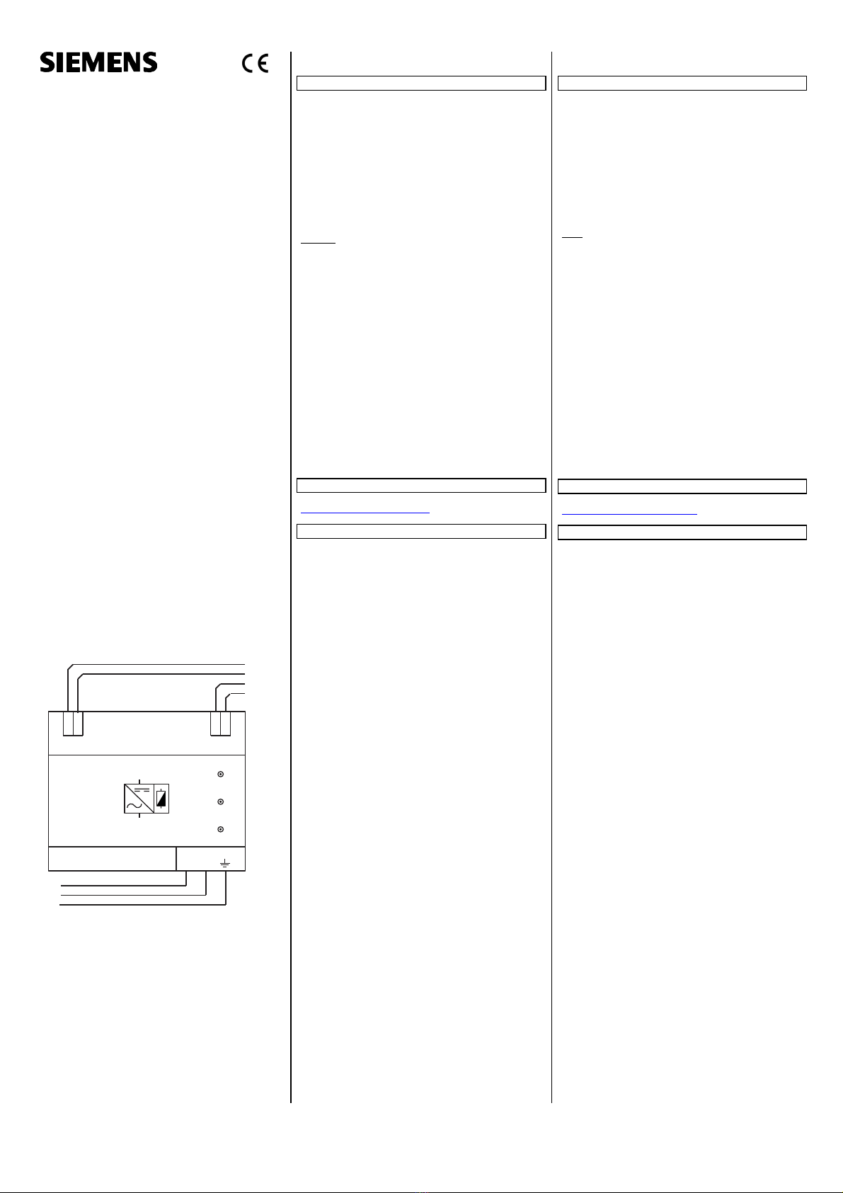
Anschlussbeispiel
Application example
RESET
Betr ieb/ ON
Überlast/Overload
5W G 1125- 1AB22
N
+-
L
+-
N
L
PE
KNX +
KNX -
DC +
DC -
s
DE
Produkt- und Funktionsbeschreibung
Die Spannungsversorgung erzeugt die für KNX erforderliche Sys-
temspannung. Die Verbindung mit der Buslinie erfolgt über die
frontseitige Busklemme.
Die integrierte Drossel verhindert den Kurzschluss der Datentele-
gramme auf der Buslinie. Durch Betätigen des eingebauten Reset-
Schalters werden die Busteilnehmer in den Grundzustand gesetzt
(Betätigung > 20 s).
Für jede Buslinie wird mindestens eine Spannungsversorgung be-
nötigt, die in einem Verteiler montiert wird. In einer Buslinie sind
maximal zwei Spannungsversorgungen zulässig. Eine zweite
Spannungsversorgung ist nur erforderlich, wenn die Betriebs-
spannung an einem Teilnehmer unter 21 V abfällt.
Hinweis: Werden zwei Spannungsversorgungen parallel an einer
Buslinie betrieben, so ist bei Aufleuchten der Überlastanzeige an
einer oder beiden Busspannungsversorgungen die Buskonfigura-
tion so zu ändern, dass keine Überlastanzeige mehr erfolgt.
Die Leitungslänge zwischen zwei parallel betriebenen Span-
nungsversorgungen ist nicht vorgegeben.
Werden mehr als 30 Busteilnehmer z.B. in einem Verteiler mit
kurzen Leitungsdistanzen (z.B. 10 m) eingebaut, soll die Span-
nungsversorgung in der Nähe dieser Busteilnehmer angeordnet
werden. Die Entfernung zwischen der Spannungsversorgung und
einem Busgerät darf max. 350 m sein.
Die Spannungsversorgung hat eine Spannungs- und Stromrege-
lung und ist damit kurzschlussfest. Kurze Netzunterbrechungen
überbrückt sie mit ca. 200 ms Pufferzeit.
Aus Gründen der Versorgungssicherheit wird empfohlen, für den
Netzanschluss der Spannungsversorgung einen eigenen, separat
abgesicherten Stromkreis zu verwenden.
Bei den Spannungsversorgungen kann die Ausgangsspannung
unverdrosselt DC 24 V an einem zusätzlichen Klemmenpaar
(gelb/weiß) frontseitig abgegriffen werden. Diese Ausgangsspan-
nung kann z.B. zur Versorgung einer zusätzlichen Linie über eine
separate Drossel genutzt werden.
Weitere Informationen
http://www.siemens.de/gamma-td
Technische Daten
Eingangsspannung
Bemessungsspannungen: AC 120-230 V, 50 ... 60 Hz
DC 220 V
Bemessungsleistungsaufnahme
ca. 24 VA
Ausgangsspannung
Bemessungsspannung DC 24 V
Schutzkleinspannung (SELV)
zulässiger Bereich DC 21 ... 30 V
Ausgangsstrom
Bemessungsstrom 160 mA (N 125/02),
320 mA (N 125/12),
640 mA (N 125/22)
Kurzschlussstrom:
begrenzt auf 1,0 A (N 125/02, N 125/12), 1,5 A (N 125/22)
Pufferzeit
bei Ausfall der Eingangsspannung ca. 200 ms
bei Bemessungsstrom
Anschlüsse
Netzspannung, Steckklemmen schraubenlos:
Abisolierlänge 10...11 mm
Es sind folgende Leiterquerschnitte zulässig:
-0,5...2,5 mm² eindrähtig
-0,5...2,5 mm² feindrähtig unbehandelt
-0,5...2,5 mm² mehrdrähtig unbehandelt
-AWG 20 (0,75 mm²) - AWG 12 (3,3 mm²)
eindrähtig, feindrähtig
Buslinie:
Busklemme (schwarz/rot), schraubenlos
0,6 ... 0,8 mm eindrähtig
Ausgangsspannung (unverdrosselt):
Kleinspannungsklemme (gelb/weiß), schraubenlos
0,6 ... 0,8 mm eindrähtig
Mechanische Daten
Abmessungen: Reiheneinbaugerät im N-Maß,
Breite 4 TE (1 TE = 18 mm)
Gewicht: ca. 260 g
Elektrische Sicherheit
Schutzart (nach EN 60529): IP 20
Umweltbedingungen
Umgebungstemperatur im Betrieb: - 5 ... + 45 C
Lagertemperatur: - 25 ... + 70 C
rel. Feuchte (nicht kondensierend): 5 % bis 93 %
EN
Product and Applications Description
The power supply unit provides the system power necessary for
KNX. The connection tothe bus line is established via the bus con-
nection block (red/black) located on the front side.
The integrated choke prevents the data telegrams from short-cir-
cuiting on the bus line. When the built-in reset switch is operated
(operation > 20s), the bus devices are returned to their initial
state.
For each bus line, at least one power supply unit is needed. Up to
two power supply units may be attached to a single bus line. A
second unit is not required unless the supply voltage at a bus de-
vice is less than 21 V.
Note: If two power supply units are operated in parallel on one
bus line and if the overload LED is lit on one or both power sup-
plies, then the bus configuration must be changed until the over-
load display disappears.
The cable length between the two power supply units operated
in parallel is not prescribed.
When more than 30 bus devices are installed in short bus cable
distance (e.g. 10 m), e.g. in distribution boards, the power supply
unit should be arranged near these bus devices. The distance be-
tween power supply unit and any of its bus devices must not ex-
ceed 350 m.
The power supply unit has a voltage and current regulation and
is therefore short-circuit proof. Short power failures can be
bridged with a backup interval of approximately 200 ms.
To ensure an uninterrupted power supply a separate circuit with
safety separation should be used for the power supply unit power
supply line.
The power supply units can supply DC 24 V power from an addi-
tional pair of terminals (yellow/white). This output voltage can be
used to power e.g. an additional line via a separate choke.
Additional Information
http://www.siemens.com/gamma-td
Technical specifications
Input voltage
rated voltage: AC 120-230 V, 50 ... 60 Hz
DC 220 V
Rated power intake
approx. 24 VA
Output voltage
rated voltage: DC 24 V
safety extra low voltage (SELV)
permissible range: DC 21 ... 30 V
Output current
rated current 160 mA (N 125/02),
320 mA (N 125/12),
640 mA (N 125/22)
short-circuit current:
limited to 1.0 A (N 125/02, N 125/12), 1.5 A (N 125/22)
Backup interval
on input voltage failure: approx. 200 ms at rated current
Connections
mains connection, screwless plug-in terminals:
strip insulation for 10 ... 11 mm
permissible conductor types/cross sections:
-0.5...2.5 mm² single core
-0.5...2.5 mm² plain flexible conductor
-0.5...2.5 mm² stranded conductor
-AWG 20 (0.75 mm²) – AWG 12 (3.3 mm²) solid, stranded
bus line:
screwless extra low voltage terminal (red/black)
0.6 ... 0.8 mm
output voltage (no choke):
screwless extra low voltage terminal (yellow/white)
0.6 ... 0.8 mm
Physical specifications
dimensions: N-system DIN-rail mounted device,
width: 4 SU (1 SU = 18 mm)
weight: approx. 260 g
Electrical safety
protection (according to EN 60529): IP 20
Environmental specifications
ambient temperature operating: - 5 ... + 45 C
storage temperature: - 25 ... + 70 C
relative humidity (non-condensing): 5 % to 93 %
A5E03391100E_RS-AF Seite 2 von 4 page 2 of 4
Bild 1/ figure 1
Bild 2 / figure 2
E3
E1
E2
E1
E2
10...11 mm
Bild 3 / figure 3
Technical Support
+49 (911) 895-7222
+49 (911) 895-7223
support.automatio[email protected]
www.siemens.de/automation/support-request
DE
Lage- und Funktion der Anzeige- und Bedienelemente
(siehe Bild 1)
A1 Kleinspannungsklemme (Busklemme rot/schwarz)
A2 Reset-Schalter
A3 Kleinspannungsklemme (gelb/weiß)
A4 Typenschild
A5 rote LED: Die Spannungsversorgung befindet sich in der
Resetstellung
A6 grüne LED: Die Spannungsversorgung
arbeitet in einem ordnungsgemäßen Betrieb
A7 rote LED: Die Teilnehmerlast ist zu hoch
oder die Buslinie ist kurzgeschlossen
A8 Schraubenlose Steckklemmen zum Anschluss der Versor-
gungsspannung (Netzklemmen)
A9 Erdungsklemme
Montage und Verdrahtung
Busklemme abziehen (Bild 2)
Die Busklemme (B2) besteht aus zwei Teilen (B2.1, B2.2) mit
je vier Klemmkontakten.
Den Schraubendreher vorsichtig in den Drahteinführungs-
schlitz des grauen Teils der Busklemme (B2.2) einführen und
die Busklemme (B2) aus dem Gerät (B1) herausziehen.
Hinweis
Busklemme nicht von unten heraushebeln! Kurzschlussgefahr!
Busklemme aufstecken
Die Busklemme in die Führungsnut des Gerätes stecken und
die Busklemme bis zum Anschlag nach unten drücken.
Busleitungen anschließen (Bild 2)
Die Busklemme (B2) ist für eindrähtige Leiter mit
0,6... 0,8 mm geeignet.
Den Leiter (B2.4) abisolieren und in Busklemme (B2)
stecken (rot = +, grau = -)
Abklemmen der Busleitung (Bild 2)
Die Busklemme (B2) abziehen und den Leiter (B2.4) der Bus-
leitung bei gleichzeitigem Hin- und Herdrehen herausziehen.
Netzspannung anschließen (Bild 3)
Die Anschlüsse für die Netzspannung bestehen aus schrau-
benlosen Steckklemmen (E1).
Die Leiter (E2) ca. 10...11 mm abisolieren und in die Klem-
men (E1) stecken.
Netzspannung abklemmen (Bild 3)
Mit dem Schraubendreher auf die Verriegelung (E3) der
Klemme (E1) drücken und den Leiter (E2) aus der Klemme
(E1) ziehen.
Installationshinweise
Das Gerät kann für feste Installation in Innenräumen, für tro-
ckene Räume, zum Einbau in Starkstromverteiler oder Klein-
gehäusen auf Hutschienen EN 60715-TH35 verwendet wer-
den.
VWARNUNG
Das Gerät darf im Starkstromverteiler (230/400V) zusammen
mit entsprechenden, VDE zugelassenen Geräten eingebaut
werden.
Das Gerät darf nur von einer zugelassenen Elektrofachkraft
installiert und in Betrieb genommen werden.
Beim Anschluss des Gerätes ist darauf zu achten, dass das
Gerät freigeschaltet werden kann.
Die geltenden Sicherheits- und Unfallverhütungsvorschriften
sind zu beachten.
Das Gerät darf nicht geöffnet werden.
Bei der Planung und Errichtung von elektrischen Anlagen sind
die einschlägigen Richtlinien, Vorschriften und Bestimmun-
gen des jeweiligen Landes zu beachten.
Allgemeine Hinweise
Die Bedienungsanleitung ist dem Kunden auszuhändigen.
Ein defektes Gerät ist mit einem Rücklieferschein der zustän-
digen Vertriebsniederlassung zurückzusenden.
Bei zusätzlichen Fragen zum Produkt wenden Sie sich bitte an
unseren Technical Support.
EN
Location / Function of the Display and Operating Elements
(see figure 1)
A1 extra low-voltage bus terminals (red/black)
A2 reset switch
A3 extra low-voltage terminals (yellow/white)
A4 type plate
A5 red LED for indicating that the power supply unit is in re-
set position
A6 green LED for indicating normal operation of the power
supply unit
A7 red LED for indicating a shorted-out bus line or a device
over-load
A8 screwless plug-in terminals for connecting the mains
(mains terminals)
A9 ground terminal
Mounting and wiring
Removing the bus terminal (Figure 2)
The bus terminal (B2) consists of two components (B2.1,
B2.2) with four terminal contacts each.
Carefully insert the screwdriver in the wire entry slot of the
grey component of the bus terminal (B2.2) and remove the
bus terminal (B2) from the device (B1).
Note
Do not try to remove the bus terminal from underneath! There is
a risk of shorting the device!
Clipping on the bus terminal
Insert the bus terminal in the guide slot of the device and
press the bus terminal downwards until it reaches the stop.
Connecting the bus cable (figure 2)
The bus terminal (B2) can be used with solid conductors,
0.6 ... 0.8 mm .
Remove the insulation from the conductor (B2.4) and insert
it in the terminal (B2) (red = +, grey = -).
Disconnecting the bus cable (figure 2)
Disconnect the bus terminal (B2) and remove the conductor
(B2.4) of the bus cable while twisting it backwards and for-
wards.
Connecting mains (figure 3)
The mains are connected via screwless plug-in
terminals (E1).
Remove approx. 10 to 11 mm of insulation from the
wire (E2) and plug it into the terminal (E1).
Disconnecting the mains (figure 3)
Press the terminal lock (E3) of the terminal (E1) with a screw-
driver and
remove the wire (E2) from the terminal (E1).
Installation notes
The device may be used for permanent interior installations
in dry locations within distribution boards or small casings
with DIN rail EN 60715-TH35.
VWARNING
The device may be built into distribution boards (230/400V)
together only with appropriate VDE-devices.
The device must be mounted and commissioned by an au-
thorised electrician.
A safety disconnection of the device must be possible.
The prevailing safety rules must be heeded.
The device must not be opened.
For planning and construction of electric installations, the
relevant guidelines, regulations and standards of the respec-
tive country are to be considered.
General Notes
The operating instructions must be handed over to the client.
A faulty device shall be returned with a Return Good Note for
Service provided by the appropriate Siemens sales office.
If you have further questions concerning the product, please
contact our technical support.
A1
A2
A3
A4
A5
A6
A7
A8
A9
B2 B2.
4
5 mm
B2
B2.4
B2.1 B2.2
B2
B2.3
A5E03391100E_RS-AF Seite 3 von 4 page 3 of 4
Bağlantıörneği
RESET
Betr ieb/ ON
Überlast/Overload
5W G 1125- 1AB22
N
+-
L
+-
N
L
PE
KNX +
KNX -
DC +
DC -
s
TR
Ürün ve fonksiyon açıklaması
Güç kaynağı ünitesi, KNX için gereken sistem gerilimini oluşturur.
Bus hattıbağlantısı, ön taraftaki bus klemensinden sağlanır.
Entegre şok bobini, bus hattındaki veri telegramlarında kısa
devreyi önler. Entegre sıfırlama düğmesine basıldığında, hattaki
cihazlar başlangıç durumuna döner (20 saniyeden uzun süre
basılır).
Her bus hattıiçin, bir dağıtıcıya monte edilmişen az bir güç
kaynağı gereklidir. Bir bus hattında en fazla iki güç kaynağı
ünitesine izin verilir. İkinci güç kaynağı ünitesi, sadece hattaki bir
cihazın çalışma gerilimi 21 V üzerinde ise gereklidir.
Not: İki güç kaynağı ünitesi bir bus hattında paralel şekilde
kullanıldığında, bus güç kaynağı ünitelerinin birindeki veya
ikisindeki aşırıyük LED'inin yanmasıdurumunda, bus
konfigürasyonu aşırıyük uyarısıalmayacak şekilde
değiştirilmelidir.
Paralel kullanılan iki güç kaynağı ünitesi arasındaki kablo
uzunluğu önceden belirlenmemiştir.
Bir dağıtıcıya 30'dan fazla cihaz kısa kablolarla (örn. 10 m) monte
edildiğinde, güç kaynağı ünitesi bu cihazların yakınına
yerleştirilmelidir. Güç kaynağı ünitesi ile bus cihazıarasındaki
mesafe en fazla 350 m olmalıdır.
Güç kaynağı ünitesi gerilim ve akım ayarına sahiptir ve kısa
devreye karşı dayanıklıdır. Ünite, kısa elektrik kesintilerini yakl.
200 ms yedekleme süreleri ile baypas eder.
Besleme güvenliği nedeniyle, güç kaynağı ünitesinin şebeke
bağlantısıiçin ayrıve sigortalıbir akım devresi kullanılması
önerilir.
Güç kaynağı ünitelerinde, şok bobinsiz DC 24 V çıkış gerilimi,
öndeki ilave bir klemens çifti (sarı/beyaz) sağlanabilir. Bu çıkış
gerilimi, ek bir hattın ayrıbir şok bobini üzerinden beslenmesi vs.
için kullanılabilir.
Daha fazla bilgi
http://www.siemens.de/gamma-td
Teknik veriler
Girişgerilimi
Anma gerilimleri: AC 120-230 V, 50 ... 60 Hz
DC 220 V
Anma güç tüketimi
Yakl. 24 VA
Çıkış gerilimi
Anma gerilimi DC 24 V
Ekstra düşük gerilim (SELV)
İzin verilen aralık DC 21 ... 30 V
Çıkış akımı
Anma akımı160 mA (N 125/02),
320 mA (N 125/12),
640 mA (N 125/22)
Kısa devre akımı:
1,0 A (N 125/02, N 125/12), 1,5 A (N 125/22) ile sınırlıdır
Yedekleme süresi
Anma akımında girişgerilimi kesildiğinde yakl. 200 ms
Bağlantılar
Şebeke gerilimi, geçmeli klemensler vidasız:
İzolasyon sıyırma uzunluğu 10...11 mm
İzin verilen iletken kesitleri:
-0,5...2,5 mm² tek telli
-0,5...2,5 mm² sade ince telli
-0,5...2,5 mm² sade çok telli
-AWG 20 (0,75 mm²) - AWG 12 (3,3 mm²)
Tek telli, ince telli
Bus hattı:
Bus klemensi (siyah/kırmızı), vidasız
0,6 ... 0,8 mm tek telli
Çıkış gerilimi (şok bobinsiz):
Ekstra düşük gerilim klemensi (sarı/beyaz), vidasız
0,6 ... 0,8 mm tek telli
Mekanik veriler
Ölçüler: N ölçüsünde DIN rayıcihazı, genişlik 4 TE (1 TE = 18
mm)
Ağırlık: yakl. 260 g
Elektrik güvenliği
Koruma türü (EN 60529 uyarınca): IP 20
Çevre koşulları
İşletimde ortam sıcaklığı: - 5 ... + 45 C
Depolama sıcaklığı: - 25 ... + 70 C
Bağıl nem (yoğuşmasız): %5 - %93
A5E03391100E_RS-AF Seite 4 von 4 page 4 of 4
Resim 1
Resim 2
E3
E1
E2
E1
E2
10...11 mm
Resim 3
Teknik destek
+49 (911) 895-7222
+49 (911) 895-7223
support.automatio[email protected]
www.siemens.de/automation/support-request
TR
Gösterge ve kontrol elemanlarının konumu ve fonksiyonu
(Bkz. resim 1)
A1 Ekstra düşük gerilim klemensi (bus klemensi
kırmızı/siyah)
A2 Sıfırlama düğmesi
A3 Ekstra düşük gerilim klemensi (sarı/beyaz)
A4 Tip etiketi
A5 KırmızıLED: Güç kaynağı sıfırlama konumunda bulunur
A6 Yeşil LED: Güç kaynağı ünitesi
normal işletimde çalışır
A7 KırmızıLED: Cihaz yükü çok yüksektir veya bus hattında
kısa devre vardır
A8 Güç kaynağınıbağlamak için vidasız geçmeli klemensler
(şebeke klemensleri)
A9 Topraklama klemensi
Montaj ve kablo bağlantısı
Bus klemensinin çıkartılması(resim 2)
Bus klemensi (B2) iki parçadan (B2.1, B2.2) ve dörder
klemens kontağından oluşur.
Tornavida, bus klemensindeki (B2.2) gri parçanın kablo giriş
açıklığına dikkatlice yerleştirilmeli ve bus klemensi (B2)
cihazdan (B1) dışarıçekilmelidir.
Not
Bus klemensini alttan kanırtmayın! Kısa devre tehlikesi!
Bus klemensinin takılması
Bus klemensini cihazın kılavuz kanalına takın ve bus
klemensini oturana kadar aşağı bastırın.
Bus kablolarının bağlanması(resim 2)
Bus klemensi (B2), çapı0,6 ... 0,8 mm olan tek telli
iletkenler için uygundur.
İletkeni (B2.4) sıyırın ve bus klemensine (B2) takın (kırmızı=
+, gri = -)
Bus kablosunun sökülmesi (resim 2)
Bus klemensini (B2) çekin ve bus kablosunun iletkenini (B2.4)
ileri geri çevirerek dışarıçekin.
Şebeke geriliminin bağlanması(resim 3)
Şebeke gerilimi bağlantıları, vidasız geçmeli klemenslerden
oluşur (E1).
İletkeni (E2) yaklaşık 10...11 mm sıyırın ve klemenslere (E1)
takın.
Şebeke geriliminin sökülmesi (resim 3)
Tornavida ile klemensin (E1) kilidine (E3) bastırın ve iletkeni
(E2) klemensten (E1) çekin.
Kurulum uyarıları
Cihaz, kuru kapalıalanlara, yüksek akım dağıtıcılarına veya
EN 60715-TH35 DIN raylarıüzerinde küçük muhafazalara
monte edilerek kullanılabilir.
VUYARI
Cihaz, yüksek akım dağıtıcılarına (230/400V) VDE onaylı
uygun cihazlar ile monte edilebilir.
Cihaz, sadece yetkili uzman elektrik personeli tarafından
monte edilmeli ve işletime alınmalıdır.
Cihazıbağlarken cihaz geriliminin kesilebilecek şekilde
bağlanmasına dikkat edin.
Geçerli güvenlik ve kaza önleme yönetmelikleri dikkate
alınmalıdır.
Cihazın içi açılmamalıdır.
Elektrik tesisatlarınıplanlama ve kurulum aşamasında, ilgili
ülkede geçerli olan yönetmelikler, talimatlar ve yasalar dikkate
alınmalıdır.
Genel uyarılar
Kullanım kılavuzu müşteriye teslim edilmelidir.
Arızalıcihazlar, yetkili satış şubesinin iade belgesi ile geri
gönderilmelidir.
Ürün ile ilgili sorularınız için lütfen teknik destek ekibimize
başvurun.
A1
A2
A3
A4
A5
A6
A7
A8
A9
B2 B2.
4
5 mm
B2
B2.4
B2.1 B2.2
B2
B2.3

This manual suits for next models

5

Other Siemens Power Supply manuals

Siemens SITOP Power 4 6EP1332-2BA00 User manual

Siemens

Siemens SITOP Power 4 6EP1332-2BA00 User manual

Siemens SIDOOR TRANSFORMER User manual

Siemens

Siemens SIDOOR TRANSFORMER User manual

Siemens Simatic ET200pro User manual

Siemens

Siemens Simatic ET200pro User manual

Siemens SITOP PSU2600 3ph User manual

Siemens

Siemens SITOP PSU2600 3ph User manual

Siemens 3RX9501-0BA00 User manual

Siemens

Siemens 3RX9501-0BA00 User manual

Siemens PSR-1 User manual

Siemens

Siemens PSR-1 User manual

Siemens 7XV5810-0CA00 User manual

Siemens

Siemens 7XV5810-0CA00 User manual

Siemens SPCP355 User manual

Siemens

Siemens SPCP355 User manual

Siemens SITOP PSE200U 3A User manual

Siemens

Siemens SITOP PSE200U 3A User manual

Siemens SITOP series User manual

Siemens

Siemens SITOP series User manual

Siemens SIMATIC NET PS598-1 Administrator guide

Siemens

Siemens SIMATIC NET PS598-1 Administrator guide

Siemens SITOP PSU300S User manual

Siemens

Siemens SITOP PSU300S User manual

Siemens SITOP SEL1200 8 x 5 A Technical Document

Siemens

Siemens SITOP SEL1200 8 x 5 A Technical Document

Siemens 4AV2102-2EB00-0A User manual

Siemens

Siemens 4AV2102-2EB00-0A User manual

Siemens MICROMASTER 430 FX Operating and maintenance instructions

Siemens

Siemens MICROMASTER 430 FX Operating and maintenance instructions

Siemens SITOP PSU8200 User manual

Siemens

Siemens SITOP PSU8200 User manual

Siemens 4AV2302-2EB00-0A User manual

Siemens

Siemens 4AV2302-2EB00-0A User manual

Siemens SITRANS I300 User manual

Siemens

Siemens SITRANS I300 User manual

Siemens FP2011-U1 User manual

Siemens

Siemens FP2011-U1 User manual

Siemens MPS-12 User manual

Siemens

Siemens MPS-12 User manual

Siemens 6ES7138-7EA01-0AA0 User manual

Siemens

Siemens 6ES7138-7EA01-0AA0 User manual

Siemens SITOP PSU400M User manual

Siemens

Siemens SITOP PSU400M User manual

Siemens FP1801-A2 User manual

Siemens

Siemens FP1801-A2 User manual

Siemens SITOP PSU8200 User manual

Siemens

Siemens SITOP PSU8200 User manual

Popular Power Supply manuals by other brands

VOLTCRAFT FPPS 9-7.2W operating instructions

VOLTCRAFT

VOLTCRAFT FPPS 9-7.2W operating instructions

MGE UPS Systems 250A Installation and user manual

MGE UPS Systems

MGE UPS Systems 250A Installation and user manual

IBM 1500VA Guide

IBM

IBM 1500VA Guide

Moeller SN4-025-BI7 installation instructions

Moeller

Moeller SN4-025-BI7 installation instructions

Puls DIMENSION CS Series instruction manual

Puls

Puls DIMENSION CS Series instruction manual

ABB ODPSE230C Installation and operating instructions

ABB

ABB ODPSE230C Installation and operating instructions

Benelec 09210FB user manual

Benelec

Benelec 09210FB user manual

Powerfinn PAP800 operating manual

Powerfinn

Powerfinn PAP800 operating manual

Akyga AK-ND-04 user manual

Akyga

Akyga AK-ND-04 user manual

moon Evolution 820S owner's manual

moon

moon Evolution 820S owner's manual

Strong International XENON instruction manual

Strong International

Strong International XENON instruction manual

Bartington MAG-03PSU Operation & maintenance manual

Bartington

Bartington MAG-03PSU Operation & maintenance manual

Inogen BA-107 Instructions for use

Inogen

Inogen BA-107 Instructions for use

Arch AQF600 Series quick start guide

Arch

Arch AQF600 Series quick start guide

Ebyte DM41-20W2412B1 user manual

Ebyte

Ebyte DM41-20W2412B1 user manual

ST VIPer12A-E Application note

ST

ST VIPer12A-E Application note

TDK-Lambda HFE1600/S series instruction manual

TDK-Lambda

TDK-Lambda HFE1600/S series instruction manual

Checkpoint TE250X Replacing

Checkpoint

Checkpoint TE250X Replacing

manuals.online logo
manuals.online logoBrands
  • About & Mission
  • Contact us
  • Privacy Policy
  • Terms and Conditions

Copyright 2025 Manuals.Online. All Rights Reserved.