manuals.online logo
Brands
  1. Home
  2. •
  3. Brands
  4. •
  5. Siemens
  6. •
  7. Surge Protector
  8. •
  9. Siemens BSPD 100 Series User manual

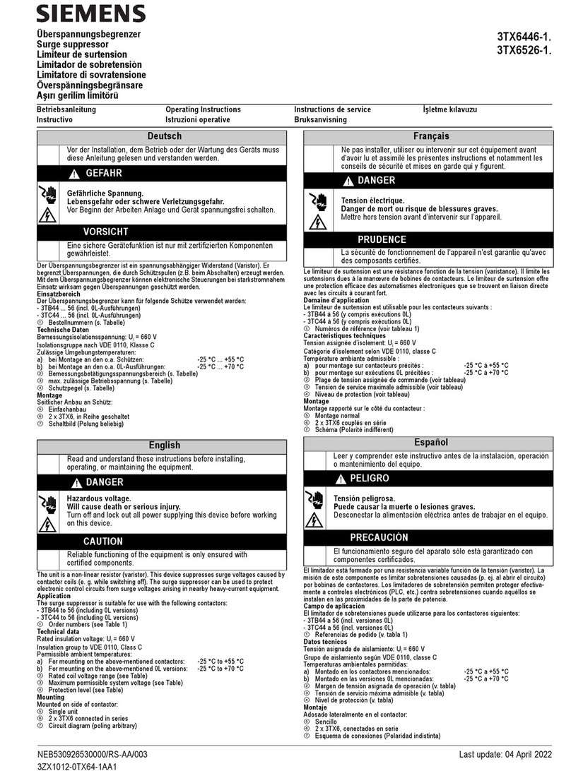
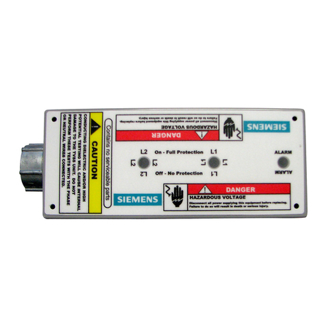
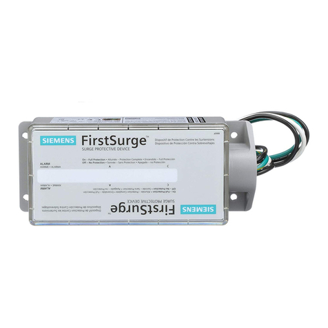
Siemens BSPD 100 Series User manual

BSPDxx Series Installation Instructions
BoltShield™ Surge Protective Devices BSPD Series for Panelboards | Installation Instructions
s
These instructions are intended as a guide for installing the Siemens BSPD series of surge protective devices into any approved
panelboard or panel that the BSPD is qualified for. It is the installer’s responsibility to ensure the proper device is selected for
the voltage system of the application.
Catalog no. System voltage
SCCR
(system rating)
Surge
current rating Poles
Volt.
code
VPR rating
L-N/L-G
Other
specifications
BSPDA /V, Ø, W* kA kA  A V • UL Type Designation: SPD Type , also
suitable for use in Type  applications
• Nominal Discharge Current (In): kA
• -pole and -pole bolt on configurations
in BQD footprint
• Flashing Dual Color LED (Green/Red)
Status Indicator
• Audible Alarm w/ Silence Switch/Button
• Form C Dry Contact, V AC, A Max,
V DC .A Max
• Pre-wired # AWG (solid copper stranded)
BSPDB /V, Ø, W kA kA  B V
BSPDC Y/V, Ø, W kA kA  C V
BSPDD V, Ø, W kA kA  D V
BSPDE Y/V, Ø, W kA kA  E V
BSPDF V, Ø, W kA kA  F V
BSPDG V, Ø, W kA kA  G V
BSPDK Y/V, Ø, W kA kA  K V
BSPDL Y/V, Ø, W kA kA  L V
BSPDS Y/V, Ø, W kA kA SV
BSPDT Y/V, Ø, W kA kA  T V
*Can also be used on Y/V, Ø, W System
Mechanical and electrical features:
An electronic alarm circuit is included on all product models.
This circuit monitors the integrity of the SPD and alerts the
user, using audible and visual means, in the event of failure.
The circuit is directly powered from the power system to
which the SPD is connected. A flashing green LED indicates
that it is operational. Upon failure of any of the MOVs in the
SPD, an intermittent audible chirp is emitted and the green
LED will change to a flashing red LED. If the user presses the
alarm silence switch/button, the audible chirp is silenced, but
the flashing red LED will remain. This is to warn the user that
the SPD has failed (and needs to be replaced) even though
the alarm has been silenced. Pressing the alarm silence
switch/button again will re-engage the audible chirp.
The Siemens BSPD surge protector will fit any location that will accept either a Siemens -pole or -pole BL/BQD type breaker,
or (with the included adapter) any location an xGB or VA type breaker will fit. Note: Each SPD comes with an adapter. There
are two surge protector types (see Figure ): -  Pole for Single Phase systems, -  Pole for Three Phase systems.
Kit # BSPDXGB is available in case the xGB/VA adapter is lost or damaged. This kit contains  each of the -pole and -pole
adapters.
2-pole3-pole
79.5
19
13.5
56.4
79.5
92.4
6.4
66.7
71.5 50.1
0.8 0.8
79.5
19
13.5
56.4
79.5
92.4
6.4
66.7
71.5
SIDE FRONT
13.5
75.2
0.8 0.8
79.5
19
13.5
56.4
79.5
92.4
6.4
66.7
71.5
SIDE FRONT
LED
Audible
Alarm
Silence
Switch/Button
Mechanical
Indication
Figure  (in millimeters)
Installation Instructions | BoltShield™ Surge Protective Devices BSPD Series for Panelboards
BSPDxx Series Installation Instructions
s
Installation Procedure:
. This device is suitable for use on a circuit capable of delivering
not more than kA rms symmetrical amperes.
. Turn off and lockout the power to the panelboard in which
the device is to be installed.
. Remove the panelboard/load center cover/deadfront.
. If installing onto the xGB/VA barrier, install supplied
mounting adapter (Figure ).
. Place SPD in position, aligning to bus as shown (Figure a and b).
. Utilizing the screws provided with the panelboard, attach
the SPD’s line terminals to the panelboard bus. Torque the
screws per panelboard specifications, or - lbs-in.
. On a single phase or -phase Wye voltage system, connect
the white pigtail wire from the SPD unit to the neutral bus
bar, making the wire as straight and short as possible.
Torque per panelboard markings, or - lbs-in.
Note: If the user is connecting the WYE SPD unit to the ground
bus bar in order to change/increase the modes of protection or
increase the surge current capacity, wrap the white wire with
green electrical tape as per code.
. On a Delta voltage system, connect the green pigtail wire from
the SPD unit to the ground bus bar, making the wire as straight
and short as possible. Torque per panelboard markings, or
- lbs-in.
. On a Hi-leg Delta system make sure that the middle contact
of the SPD matches the B-phase (center bus).
. The remote contacts (VAC A; VDC .A) are factory
configured series/parallel with all modules interconnected to
a single connector for ease of monitoring the status of the
suppressor.
. A typical application circuit for the remote contacts is shown
in Figure , where a power source can be used to turn off a
circuit or remote alarm in the event of suppressor failure (or
turn-on a circuit/alarm).
. Replace the panelboard cover/deadfront and restore panelboard
power.
. Verify that the green indicator light is flashing for all BSPDs installed.
Published by
Siemens 2020
Siemens Industry, Inc.
5400 Triangle Parkway
Norcross, GA 30092
Siemens Technical Support:
1-800-333-7421
[email protected]
Printed in USA
Order No. CBIM-BSPDI-0320
All Rights Reserved
© 2020, Siemens Industry, Inc.
usa.siemens.com/surge
These instructions do not purport to cover all details or variations in equipment, or
to provide for every possible contingency to be met in connection with installation,
operation or maintenance. Should further information be desired, or should
particular problems arise, which are not covered sufficiently for the purchaser’s
purposes, the matter should be referred to the local Siemens sales office. The
contents of this Instruction manual shall not become part of or modify any prior
or existing agreement, commitment or relationship. The sales contract contains
the entire obligation of Siemens. Trademarks-Unless otherwise noted, all names
identified by ® are registered trademarks of Siemens AG or Siemens Industry, Inc.
The remaining trademarks in this publication may be trademarks whose use by
third parties for their own purposes could violate the rights of the owner.
Turn off and lock out all power supplying this device before
working on this device.
Replace all covers before power supplying this device
is turned on.
Hazardous Voltage.
Will cause death or serious injury.
Desenergice totalmante antes de instalar o darle servicio.
Reemplace todas las barreras y cubiertas antes de
energizar el interruptor.
Tensión peligrosa.
Puede causar la muerte o lesiones graves.
Couper l’alimentation de l’appareil et barrer avant de
travailler.
Remplacez touts les couverts avant que
l’approvisionnement de pouvoir soit alimenté.
Tension dangereuse.
Danger de mort ou risque de blessures graves.
Español / Francois
usa.siemens.com/surge
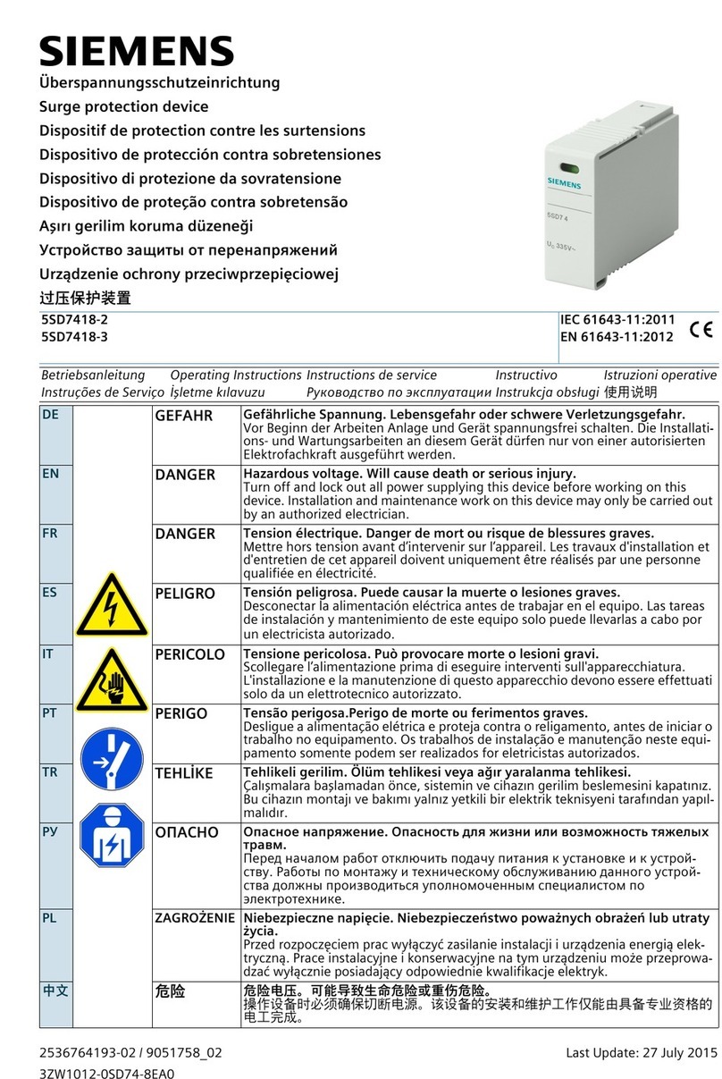
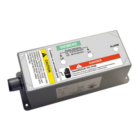
This manual suits for next models

11

Other Siemens Surge Protector manuals

Siemens SP-36 Maintenance and service guide

Siemens

Siemens SP-36 Maintenance and service guide

Siemens 5SD7463-0 User manual

Siemens

Siemens 5SD7463-0 User manual

Siemens 3TX7402-3A User manual

Siemens

Siemens 3TX7402-3A User manual

Siemens 5SD7418-2 User manual

Siemens

Siemens 5SD7418-2 User manual

Siemens 5SD7 502-0KB User manual

Siemens

Siemens 5SD7 502-0KB User manual

Siemens TPS4-01 Troubleshooting guide

Siemens

Siemens TPS4-01 Troubleshooting guide

Siemens 5SD7483-5 User manual

Siemens

Siemens 5SD7483-5 User manual

Siemens SICROWBAR 7VV3003 User manual

Siemens

Siemens SICROWBAR 7VV3003 User manual

Siemens SPD4home User manual

Siemens

Siemens SPD4home User manual

Siemens 5SD7418 Series User manual

Siemens

Siemens 5SD7418 Series User manual

Siemens 5SD7442-1 User manual

Siemens

Siemens 5SD7442-1 User manual

Siemens FireSeeker FS-100 User manual

Siemens

Siemens FireSeeker FS-100 User manual

Siemens SP-37 Maintenance and service guide

Siemens

Siemens SP-37 Maintenance and service guide

Siemens TPSA9040 User manual

Siemens

Siemens TPSA9040 User manual

Siemens TPS3 03 DC User manual

Siemens

Siemens TPS3 03 DC User manual

Siemens 3TX7462-3 User manual

Siemens

Siemens 3TX7462-3 User manual

Siemens TPS3 03 User manual

Siemens

Siemens TPS3 03 User manual

Siemens TPS3 User manual

Siemens

Siemens TPS3 User manual

Siemens HNM3M120 User manual

Siemens

Siemens HNM3M120 User manual

Siemens 5SD7422-0 User manual

Siemens

Siemens 5SD7422-0 User manual

Siemens 5SD7444-1 User manual

Siemens

Siemens 5SD7444-1 User manual

Siemens 3TX6446-1 Series User manual

Siemens

Siemens 3TX6446-1 Series User manual

Siemens TPS3 09 User manual

Siemens

Siemens TPS3 09 User manual

Siemens TPS3 12 User manual

Siemens

Siemens TPS3 12 User manual

Popular Surge Protector manuals by other brands

Philips Slimline SPP1180WA Specifications

Philips

Philips Slimline SPP1180WA Specifications

Philips SPP1028A/17 user manual

Philips

Philips SPP1028A/17 user manual

M-system MDP-200T instruction manual

M-system

M-system MDP-200T instruction manual

OPTI-UPS SBUH-721 Specifications

OPTI-UPS

OPTI-UPS SBUH-721 Specifications

Total Protection Solutions 80 Installation, operation and maintenance manual

Total Protection Solutions

Total Protection Solutions 80 Installation, operation and maintenance manual

SNAP Watt Box WB-200-2 owner's manual

SNAP

SNAP Watt Box WB-200-2 owner's manual

hager EUS 315 Mounting instructions

hager

hager EUS 315 Mounting instructions

Sven SF-05 user manual

Sven

Sven SF-05 user manual

Emerson 500 Series Installation, operation and maintenance manual

Emerson

Emerson 500 Series Installation, operation and maintenance manual

Balt Power Tower 27735 Assembly instructions

Balt

Balt Power Tower 27735 Assembly instructions

Energenie SIS-PMS-LAN user manual

Energenie

Energenie SIS-PMS-LAN user manual

Bodet 907 052 installation manual

Bodet

Bodet 907 052 installation manual

Joslyn 1456-85-L Installation and maintenance manual

Joslyn

Joslyn 1456-85-L Installation and maintenance manual

Energenie EG-PMS2 user manual

Energenie

Energenie EG-PMS2 user manual

Patton electronics 530 user manual

Patton electronics

Patton electronics 530 user manual

RectorSeal RSH-50 installation instructions

RectorSeal

RectorSeal RSH-50 installation instructions

ISOL-8 SubStation 3 user manual

ISOL-8

ISOL-8 SubStation 3 user manual

Eupen JB007 installation instructions

Eupen

Eupen JB007 installation instructions

manuals.online logo
manuals.online logoBrands
  • About & Mission
  • Contact us
  • Privacy Policy
  • Terms and Conditions

Copyright 2025 Manuals.Online. All Rights Reserved.