Table of contents
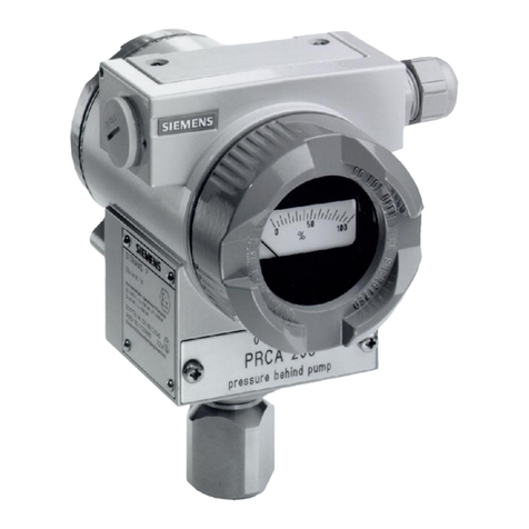
SITRANS P DS III/P410 with PROFIBUS PA
Operating Instructions, 02/2016, A5E00053276-08 7
6.5.2 Operation using buttons..........................................................................................................79
6.5.3 Setting/adjusting electrical damping .......................................................................................79
6.5.4 Calibrate zero point.................................................................................................................80
6.5.5 Locking of buttons and functions ............................................................................................81
6.5.6 Measured value display ..........................................................................................................82
6.5.7 Unit..........................................................................................................................................84
6.5.8 Bus address ............................................................................................................................88
6.5.9 Device operation type .............................................................................................................88
6.5.10 Position of the decimal point...................................................................................................90
6.5.11 Display of the zero-point adjustment ......................................................................................90
6.5.12 LO calibration..........................................................................................................................91
6.5.13 HI calibration ...........................................................................................................................92
7 Operator control functions via PROFIBUS............................................................................................. 95
7.1 Communications structure for PROFIBUS PA .......................................................................95
7.1.1 Overview .................................................................................................................................95
7.1.2 Block model for collection and processing of measured values.............................................95
7.1.3 Pressure transducer block ......................................................................................................98
7.1.3.1 Pressure transducer block (transducer block 1) .....................................................................98
7.1.3.2 Linearization type function group..........................................................................................100
7.1.3.3 Units of the pressure transducer block .................................................................................102
7.1.4 Electronics temperature transducer block ............................................................................103
7.1.5 Analog input function block...................................................................................................104
7.1.6 Totalizer function block .........................................................................................................105
7.2 Overview of operating functions ...........................................................................................106
7.3 Measurement ........................................................................................................................106
7.4 Settings .................................................................................................................................107
7.4.1 Overview of settings..............................................................................................................107
7.4.2 Settings .................................................................................................................................107
7.4.3 Pressure measurement.........................................................................................................107
7.4.4 Level measurement ..............................................................................................................108
7.4.5 Flow measurement ...............................................................................................................111
7.4.6 Adjusting to a desired process value....................................................................................114
7.5 Electrical damping (filter time constant)................................................................................116
7.6 Key lock and write protection................................................................................................116
7.7 Warning and alarm limits ......................................................................................................117
7.8 Failure behavior ....................................................................................................................119
7.8.1 Overview of failure behavior .................................................................................................119
7.8.2 Output ...................................................................................................................................119
7.8.3 Totalizer output .....................................................................................................................119
7.9 Diagnostics functions............................................................................................................120
7.9.1 Operating hours counter .......................................................................................................120
7.9.2 Calibration interval and service interval ................................................................................120
7.9.3 Clearing warning ...................................................................................................................121
7.9.4 Clearing the alarm.................................................................................................................121
7.9.5 Min/max indicator..................................................................................................................122
7.10 Simulation .............................................................................................................................122
7.10.1 Overview of simulation..........................................................................................................122
