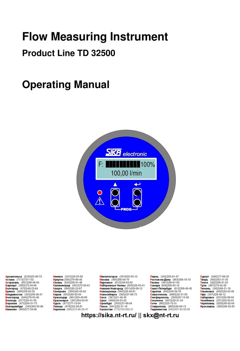
SIKA VO VA Series User manual

Please keep this operating manual for future reference.
If the appliance is resold, please provide the operating manual along with it.
© SIKA •Ba_VO • 06/2015 .
Oval gear flow meters VO
Types VO…VA, VO…VP, VO…AP
Sizes 015, 06, 1, 2, 5, 10, 50, 115
Operating manual
(Translation)
Betriebsanleitung
....................................................Seite 1 - 34
Operating manual
..................................................page 35 - 68

VO
- 36 - © SIKA •Ba_VO • 06/2015
Table of contents page
0About this operating manual.......................................................................................37
1Device description .......................................................................................................38
1.1 Intended use..............................................................................................................40
1.2 Warranty and exclusion of liability............................................................................40
2Safety instructions.......................................................................................................41
3Construction and function...........................................................................................42
4Installation and operating of the measuring chamber housing.................................43
4.1 Installation instructions............................................................................................43
4.2 Mounting....................................................................................................................44
5Sensor and display unit ...............................................................................................45
5.1 Mounting....................................................................................................................45
5.2 Electrical connection ................................................................................................46
5.3 Replacing the battery (displays 1 and 2)...................................................................48
6Operation and handling...............................................................................................49
6.1 Display.......................................................................................................................49
6.2 Key functions in normal mode..................................................................................50
6.3 Operating menu.........................................................................................................50
6.4 Open collector pulse output (displays 2 and 3).........................................................56
6.5 Level and parameter operating menu......................................................................57
7Problems .....................................................................................................................59
8Maintenance, cleaning, repairs, hazardous substances............................................59
8.1 Maintenance and cleaning ........................................................................................59
8.2 Repair, hazardous media ..........................................................................................60
9Disposal .......................................................................................................................60
10 Technical data .............................................................................................................61
10.1 Characteristics VO.....................................................................................................61
10.2 Dimensions................................................................................................................63
10.3 Pressure drop ...........................................................................................................65
Copyright notice:
The reproduction, distribution and utilization of this operating manual as well as the communication of
its contents to others without express authorization is prohibited. Offenders will be held liable for the
payment of damages. All rights reserved in the
event of the grant of a patent, utility model or design.

VO About this operating manual
Technical changes reserved - 37 -
0About this operating manual
•The operating manual is aimed at specialists and semi-skilled personnel.
•Before each step, read through the relevant advice carefully and keep to the specified
order.
•Thoroughly read and understand the information in the section "Safety instructions".
If you have any problems or questions, please contact your supplier or contact us directly at:
Dr. Siebert & Kühn GmbH & Co. KG
Struthweg 7-9 • D - 34260 Kaufungen
05605-803 0 • 05605-803 54
info
@
sika.net • www.sika.net
Hazard signs and other symbols used:
CAUTION! Electric current!
This sign indicates dangers which could arise from handling of electric current.
WARNING! / CAUTION! Risk of injury!
This sign indicates dangers that cause personal injuries that can lead to health defects or
cause considerable damage to property.
CAUTION! High temperature!
This sign indicates dangers resulting from high temperature that can lead to health defects or
considerable damage to property.
CAUTION! Risk of injury in the case of excessive pressure!
This sign indicates dangers which could arise from excessive pressure in a piece of equip-
ment.
CAUTION! Material damage!
This sign indicates actions which could lead to possible damage to material or environmental
damage.
ADHERE TO OPERATING MANUAL!
NOTICE!
This symbol indicates important notices,
tips or information.
Pay attention to and comply with infor-
mation that is marked with this symbol.
Follow the specified instructions and steps.
Adhere to the given order.
Check the specified points or notices.
Reference to another section, document or
source.
•Item.

Device description VO
- 38 - © SIKA •Ba_VO • 06/2015
1Device description
The oval gear flow meter of the series VO is a volume displacement flow meter. It is intended
to be used for the simple and reliable measurement of volumes and flow rate. It has an ex-
tremely robust design and combines years of experience with state-of-the-art technologies.
The VO can be used in various industries, e.g. mechanical engineering, plant construction,
food industry, semiconductor industry, environment industry, automotive industry, etc.
Due to the available material combinations of the housing, oval wheels and gaskets VO is also
suitable for measuring aggressive or corrosive media.
Components:
The VO consists of the two main components, measuring chamber with oval wheels and
pulse sensors / electronic with display.
Electronics with display or
pulse sensors M12x1 (without illustration).
Upper housing part.
Process connections (input and output
side).
Lower housing part.
Cable gland (displays 1+2).
Oval wheels.
Gasket.
Versions:
The VO can be supplied in different types and sizes. Furthermore, the VO can be equipped
with different display units or a sensor.
The process connection is available as female
thread or flange connection.
The types differ in terms of the combinations of
materials used in the housing, oval wheels and
seals. There are 8 sizes for measuring ranges
from 0.03...700 l/min.
The display unit is available in three sizes and
can be mounted on the VO or installed offset on
the wall. In addition, the VO can also be combined with a sensor or high temperature "sen-
sor".
Further information on the material combinations, size, display units and sensors can be
found in our catalogues at "catalogues.sika.net"
VO 10 VP with display 3 and
view from below without lower part
Threaded version
Flanged version

VO Device description
Technical changes reserved - 39 -
Type plates:
The type plates are located on the measuring
chamber housing or on the housing of display de-
vice.
It contains the most important data (Example).
Scope of delivery and accessories:
Check the delivered items and ordered accessories for completeness. Compare the device
data with the data on the delivery note and in the order records.
Device:
1x VO according to the order data.
2x Process connection protective caps
1x Operating manual.
Packaging or transport protection (if applicable).
Accessories:
Connection cable with moulded M12x1 coupling socket.
Coupling socket for self-assembly.
Lithium battery 3.6 V.
Report any in-transit damage immediately. Damage reported at a later date shall not be
recognized.
Examples type plates

Device description VO
- 40 - © SIKA •Ba_VO • 06/2015
1.1 Intended use
The VO is only intended to be used for measurement of liquid volumes or volumetric flow
rates.
The device is only intended to be applied with the media which is compatible with the combi-
nation of materials being used. The operator must ensure that the materials used (wetted
parts) of the device compared with the measured liquid are chemically resistant.
WARNING! No safety component!
The oval gear flow meter of the series VO is not a safety component in accordance with
Directive 2006-42-EC (Machine Directive).
Never use the VO as a safety component.
The operational safety of the device supplied is only guaranteed by intended use. The speci-
fied limits (§ 10 "Technical data") may under no circumstances be exceeded
Before ordering and installation, check that the VO and its material combinations is suitable
for your applications.
1.2 Warranty and exclusion of liability
Please refer the contractual terms and conditions relating to delivery for the scope and peri-
od of warranty.
Warranty claims shall be conditional to correct installation and commissioning in accordance
with the operating instructions of the device.
We accept no liability for any damage or malfunctions resulting from incorrect installation,
in-appropriate use of the device or failure to follow the instructions in this operating manual.

VO Safety instructions
Technical changes reserved - 41 -
2Safety instructions
Before you install the VO, read through this operating manual carefully. If the instructions
contained within it are not followed, in particular the safety guidelines, this could result in
danger for people, the environment, and the device and the system it is connected to.
The VO corresponds to the state-of-the-art technology. This concerns the accuracy, the op-
erating mode and the safe operation of the device.
In order to guarantee that the device operates safely, the operator must act competently and
be conscious of safety issues.
SIKA provides support for the use of its products either personally or via relevant literature.
The customer verifies that our product is fit for purpose based on our technical information.
The customer performs customer- and application-specific tests to ensure that the product
is suitable for the intended use. With this verification all hazards and risks are transferred to
our customers; our warranty is not valid.
Qualified personnel:
The personnel who are charged for the installation and operation of the VO must hold a
relevant qualification. This can be based on training or relevant tuition.
The personnel must be aware of this operating manual and have access to it at all times.
General safety instructions:
In all work, the existing national regulations for accident prevention and safety in the
workplace must be complied with. Any internal regulations of the operator must also be
complied with, even if these are not mentioned in this manual.
Degree of protection according to EN 60529:
Ensure that the ambient conditions at the site of use does not exceed the requirements
for the stated protection rating (§ 10 "Technical data").
Check that the materials used of the device compared with the measured liquid are
chemically resistant (§ 10.1 "Wetted parts' materials").
The gaskets or sealing elements must be handled with care according to the operating in-
structions.
Only use the VO if it is in perfect condition. Damaged or faulty devices must be checked
without delay and, if necessary, replaced.
When fitting, connecting and removing the VO use only suitable appropriate tools.
Do not remove or obliterate type plates or other markings on the device, as otherwise the
warranty is rendered null and void
Special safety instructions:
Warnings that are specifically relevant to individual operating procedures or activities can be
found at the beginning of the relevant sections of this operating manual.
Construction and function VO
- 42 - © SIKA •Ba_VO • 06/2015
3Construction and function
The two main components of the VO are the measuring chamber housing and the display
unit. Measurement is performed in the measuring chamber housing. The pulses generated
there are evaluated in the display unit and displayed as a volume or flow value on the LCD
display.
The display unit has its own housing and is mounted on the measuring chamber housing. Op-
tionally, the display unit may also be placed on the wall, offset from the measuring chamber
housing.
Construction (mechanical):
The VO consists of measuring chamber housing
with two pivoted oval wheels .
The gear teeth of the two high-precision internal
gears mesh. Through these gear teeth and the
slight contact to the measuring chamber wall, the
input side is separated and sealed from the out-
put side .
Between the individual oval wheels and the adjacent
measuring chamber wall, a movable measuring
chamber is formed, with a defined partial vol-
ume.
Function:
The oval gear flow meter of the series VO belongs to the group of direct volumetric meters
with movable partition walls.
The flow of medium drives the two oval wheels, and they roll over and away from each other
in opposite directions.
The measuring chambers formed by the oval wheels
thus move from the input to the output side. For each
revolution of the oval wheels, two partial volumes each
(i.e. a total of four) are transported through the VO
(see figure).
The rotary motion of the oval wheels is transmitted to
a sensor element via magnets. The number of revolu-
tions is directly proportional to the flow rate.
The output signal of the sensor is evaluated by the
electronics and shown in the display.

VO Installation and operating of the measuring chamber housing
Technical changes reserved - 43 -
4Installation and operating of the measuring chamber housing
Before installing the device, check that
the pressure bearing parts have not been damaged during transportation
the wetted materials of the device are suitable for the media being used (§ 10.1
"Wetted parts' materials").
the equipment is switched off and is in a safe and de-energised state.
the equipment is depressurised and has cooled down.
SUITABLE TOOLS:
Use only suitable tools of the correct size.
4.1 Installation instructions
Please observe the following installation instructions:
•Only trained personnel who have been authorized by the system operator are allowed to
perform assembly, electrical installations, commissioning, maintenance and operation.
You must have read and understood the instructions and follow their instructions strictly.
•Our oval gear flow meters are precision flow meters. Inlet and outlet are covered with
protective caps against foreign substances.
Remove caps shortly before putting the device into operation.
•As indicated on the type plate parameters are maximum values and must not be exceed-
ed. Operating parameters are specified in the contract documents. Use with other opera-
tional data only after consultation and stating the order number.
•Install the oval gear flow meter in the pressure pipe behind the pump (approximately 3 m
liquid column pressure drop for nominal flow rate)
•Pay attention to the tightening torque (§ 10.1.1 "Tightening torque") of your VO while
tightening the process connection (thread, flange).
•Install the oval gear flow meter in such a way, that it remains filled with liquid also in
non-operating condition.
•To avoid measuring inaccuracies due to gas bubbles or contamination, preventive
measures must be taken (e.g. gas separator or type N strainer)
•Oval gear flow meters intended for liquid food products must be cleaned thoroughly be-
fore putting them into operation (§ 8.1 "Maintenance and cleaning").

Installation and operating of the measuring chamber housing VO
- 44 - © SIKA •Ba_VO • 06/2015
4.2 Mounting
CAUTION! Risk of injury in the case of excessive pressure!
Operating pressurized installations can lead to health defects or cause considerable
damage to property.
Make sure that the installation is fully depressurised before mounting/dismounting
Caution! Risk of injury due to high temperature!
The VO and its components can become very hot during the operation und may cause
burns if touched.
Never touch the VO or its components at high temperatures.
Make sure that the installation has cooled down before mounting/dismounting.
Remove any impurities from the pipe work. Flush the pipeline, when doing so, replace
the VO with a suitable piece of piping.
Do not remove the caps on the in- and outlet of the VO until the device is being installed
to prevent the penetration of foreign substances.
Any flow direction, if applicable pay attention to the arrow on the measuring chamber
housing.
The housing cover of the VO is to be placed vertically so that the axes of the oval gear are
in a horizontal position independent of the position of the pipe.
Install the oval gear flow meter in the pipeline free from strain.
Installation position:
Correct!
Wrong!
Horizontal pipe work:
Vertical pipe work:

VO Sensor and display unit
Technical changes reserved - 45 -
5Sensor and display unit
Sensor:
For connection to evaluation electronics or a PLC of the user there's a separate sensor with
M12x1 thread in stock. In addition to the standard sensor there is a high temperature sensor
for the types VO…VA available.
NPN / PNP output signal (standard).
PNP output signal (high temperature)
Display unit:
The display unit consists of the sensor integrated in the measurement chamber housing, the
electronic and the display with control panel. The electronic indicator evaluates the original
impulses of a VO in a quantity or flow indicator. The indicator is an LC Display.
The volume or the flow rate is calculated using a multiplication of the pulses generated with
the device-specific K-factor.
For devices that are supplied with calibration, you receive a test certificate with your device,
the device-specific pulse factor (K factor) in pulses per litre will be listed. This K factor is also
specified on the device. If the device is supplied without calibration, the standard K factor
should be used (§ 10.1.1 "K-factor").
The VO can be set on request at the factory to the operating conditions specified in the order.
The values which are set in the electronic display are shown in the attached data sheet con-
figuration.
5.1 Mounting
5.1.1 Sensor
Screw in the sensor until it stops and then unscrew it again sufficiently until signals can be
detected (e.g. by checking the blinking LED on the plug).
5.1.2 Display unit
Installation instructions:
Please observe the following installation instructions:
•The display unit 1 can be only mounted directly onto measur-
ing chamber housing.
•The display units 2 and 3 can either be mounted on measur-
ing chamber housing or separately on the wall.
Horizontal pipe work :

Sensor and display unit VO
- 46 - © SIKA •Ba_VO • 06/2015
•Observe the ambient (temperature, degree of protection) at
the installation site.
•The display can be rotated in 90° steps.
•The cable gland (Displays 2+3) must face downwards or to
the side (Illustration).
IMPORTANT! Exchange of display unit and sensors!
The display unit and the sensors (for the pulse pick, if appli-
cable for temperature measurement) can be exchanged un-
der operating conditions.
5.2 Electrical connection
CAUTION! Electric current!
The electrical connection of the VO should only be carried out by a fully qualified electrician.
De-energize the electrical system before connecting the VO.
5.2.1 Sensor
For connection to evaluation electronics or a PLC or of the user sensor must be powered with
10-30 VDC. 3m connection with PVC cable 3 x 0.34 mm ². 2 LEDs on the sensor for supply and
contact.
Terminal assignment for
NPN-Sensor:
PNP-Sensor:
5.2.2 Display unit
Power supply:
Display units 1 and 2
•The power supply occurs via a 3.6 V lithium battery integrated in the UP-GF polyester
housing.
Display unit 3
•24 V with current output 4…20 mA.
Pulse output (only displays 2+3):
The display units 2 and 3 contain two cable bushings for one external sensor and/or pulse
output. The terminal compartment has up to two reed sensors that can be connected via
plug-in connectors. The electronics can be combined with any meter that uses reed sensors.
Vertical pipe work
:

VO Sensor and display unit
Technical changes reserved - 47 -
External Sensor (only displays 2+3):
The external reed sensor can transmit pulses to either pulse input A or B depending on the
measuring task and the operating mode. A sliding switch AB is provided on the connec-
tion circuit board for this purpose. An external sensor with a cable length of up to 30m can
always be connected at terminals 1 and 2. Additionally, an internal reed sensor can be used
to transmit pulses to the other pulse input. It is therefore possible to carry out consumption
measurements.
Terminal assignment:
Display 2
Display 3

Sensor and display unit VO
- 48 - © SIKA •Ba_VO • 06/2015
5.3 Replacing the battery (displays 1 and 2)
The battery service life is approx. 3 years (depending on the operating hours).
After inserting a new battery, it can take up to 3 minutes until the full contrast of the display
is visible.
This physical effect is typical for the used battery and has no effect on the battery life.
Replacing the battery:
1. Unscrew the hex socket head cap
screw at the front of the housing. The
electronics housing is released from the
oval gear flow meter.
Caution with the display 1: The electron-
ics of the display unit is connected to the
oval gear flow meter. Remove the con-
nector from the electronics.
2. Place the electronics with the display
facing downwards on a suitable surface.
Unscrew the 4 crosshead screws on
the underside of the circuit board.
3. Extract the circuit board from the
electronics.
4. Remove the battery from the holder
and insert a new battery. Only use origi-
nal batteries.
Pay attention to the correct polarity!
5. Assembly is carried out in reverse or-
der to disassembly.
6. Make sure the o-ring is positioned
correctly when placing the electronics on
the oval gear flow meter.
Make sure the display is positioned correctly (check via the film at the front) before in-
stalling the 4 crosshead screws
.
Incorrect installation may damage the display!
Exploded drawing of display unit 1
Exploded drawing of display unit 2

VO Operation and handling
Technical changes reserved - 49 -
6Operation and handling
CAUTION! Material damage!
Erratic or rapid flow increase when starting up the VO may cause damage to the oval
wheels, bearings and seals.
Start up the oval gear flow meter with slowly increasing flow.
Before switching on for the first time, check that
the VO has been installed correctly and that all screw connections are sealed.
the electrical wiring has been connected properly
the measuring system is vented by flushing.
6.1 Display
The display is an 8-digit 7-segment numeric display containing 20 information elements. The
information elements are used to display the unit, operating statuses, sensor signals, pro-
gramming symbols, etc.
Use the "" key to select the display: Q →V1 →V2 →Q →V1 →V2 ….
Explanation of the display symbols:
•“A” or “B” is displayed for approx. 0.5 s when a pulse is generated at the sensor.
•“Prog” indicates that the device is in programming mode.
•“Q” and the respective flow unit are displayed together with the flow rate.
•Volumes are displayed via “V1” total volume meter or “V2” daily volume meter. The vol-
ume units are shown accordingly. The “V2” meter can always be reset via the “R” key.
The “V1” meter can only be reset via the programming menu after entering the correct
password. The password prompt is deactivated upon delivery
•The menu steps and the volume meters V1 or V2 are displayed in the programming mode
and the normal mode respectively via the numbers 1/2/3/4/5/6.
The daily volume meter and total volume meter do not display values below zero.

Operation and handling VO
- 50 - © SIKA •Ba_VO • 06/2015
6.2 Key functions in normal mode
Press the "▲" key to go to the next displayed mode.
If the daily volume is displayed, it can be reset to zero by
pressing the “R” key.
The total volume meter “Volume 1” can only be reset in
programming mode after entering a password (§ 6.3.12).
6.3 Operating menu
6.3.1 Key functions
Press the "" key for approx. 2 s to go to the programming mode (“1” and “Prog” appear on
the left and at the top of the display respectively). Press the “R” key to navigate through the
individual levels. The normal mode is reached automatically after level 146 software version.
After reaching the level which needs to be altered, press the "" key once. “Prog” flashes
and the value can be altered as described in the examples.
Examples:
Level 2 - flow or volume unit:
For example, the unit “gal” is displayed. Press the "▲" key to change the unit setting to “g”
(continue to press the key to set the units “kg”, “t”, “l” or “m³”). Once the desired unit has
been set, press the "" key to save it.
Level 6 - K-Factor:
The K factor is displayed as 0660.0000. This needs to be changed to 0200.000. The first digit
can be altered when “Prog” flashes. Press the "" key to move to the second digit. Press the
"▲" key to increase the value by “1”. Press the key until “2” has been set and use the "" key
to move to the next digit. Continue this process until all the values have been set as desired.
6.3.2 Operating modes (level 1)
6.3.2.1 Return identification
Return identification is possible when using two sensors at one measuring chamber. The
flow is displayed as a negative value during the return process. At the same time, both vol-
ume meters are decremented. Return identification is only possible when pulses A and B
overlap. The maximum input frequency that can be processed is 200 Hz. Negative values are
not displayed after the V1 or V2 meter has returned to “0”. The quantity is lost! “E” appears
on the display during the return process. The message “E” is saved and can be deleted by
pressing the "" key.
Select operating mode “1”

VO Operation and handling
Technical changes reserved - 51 -
6.3.2.2 Total volume measurement
“A” + “B” is calculated as the total volume measurement for the volume / mass measure-
ment. There is no return identification. Separate K factors are applied.
The total of “A+B” is displayed at all meters. K factor A and B can be set separately.
Select operating mode “2”.
6.3.2.3 Difference measurement
“A-B” is calculated as the difference measurement for the volume / mass measurement.
There is no return identification. Separate K factors are applied.
The electronics can record pulses from two different measuring chambers. The forward
quantity is, e.g., measured by the internal reed sensor “A”. The external reed sensor then
measures the pulses of the separately mounted return quantity meter via the external reed
sensor “B” (terminal positions 1+2). A K factor must be programmed for each sensor. The
difference “A-B” is displayed at all the meters. A number below zero is impossible; the
smallest value that can be displayed at the volume meter is “0”. Select operating mode “3”.
6.3.3 Volume units (level 2)
The displayed volume unit can be freely selected (litters, cubic meters, gallons, grams, kilo-
grams, tonnes).
There is no automatic conversion of the previously accumulated volume in the new unit when
changing the selected volume unit in level 2 or when changing the number of digits after the
decimal point for V in level 5. All the current meter readings are deleted (reset) when chang-
ing the volume unit. It is recommended to activate password protection to prevent accidental
deletion. Always observe possible effects on the current output.
Mass display
To display the mass, a fixed density in kg/m³ and an alpha value in kg/m³/°C must be entered
in the programming menu. The density and the alpha value are used to convert volumes to
mass. When selecting a mass volume unit (g, kg or t), the calculated or fixed density is ac-
cessed automatically depending on whether a temperature sensor is connected or not.
6.3.4 Time units (level 3)
The time unit for the flow display (h/ min/ s) can be freely selected.

Operation and handling VO
- 52 - © SIKA •Ba_VO • 06/2015
6.3.5 Digits after the decimal point for flow or volume (level 4 and 5)
The number of digits after the decimal point can be set separately for the flow and volume
display.
Select up to 3 digits after the decimal point.
Always observe possible effects on the current output when making changes!
6.3.6 K factors (level 6 and 12)
The volume or flow is calculated by multiplying the generated pulses with the device-specific
K factor.
A K factor must be programmed for each meter in the difference measurement and the to-
tal volume measurement mode.
6.3.7 Density calculation (level 13)
Example 1: No temperature sensor connected
The expected process density is entered in level 13. This fixed density is used to continuously
calculate the mass volume.
Example 2: PT1000 connected (only for display 3)
Enter the density of the medium at 20°C in level 13. Enter the alpha value, i.e. the change of
medium density, in kg/m³/°C in level 23. The alpha value is always positive! The temperature
of the connected PT1000 is recorded and displayed in level 14. The temperature is recorded
in 0.5° steps. (Please observe the permissible temperature for meters and the electronics!)
The electronics uses the density, alpha value and the recorded temperature to calculate the
operating density of the medium. This variable operating density is used to calculate the
mass volume.
Example:
Temperature: 27°C (can be read in level 14)
Density at 20°C: 998.2 kg/m³ (must be entered in level 13)
Alpha-values: 0.2 kg/m³/°C (must be entered in level 23)
Calculation:
27°C – 20°C = 7°C (temperature difference to 20°C )
7°C * 0.2 kg/m³/°C = 1.4 kg/m³ (change of density compared to 20°)
998.2 kg/m³ - 1.4 kg/m³ = 996.8 kg/m³ (new operating density for calculation with the cur-
rent measured volume)
6.3.8 Medium temperature (level 14) (only display 3)
The multifunctional electronics of the display 3 provides a connection for a PT1000 sensor
(optional). The current measured temperature is displayed in 0.5°steps in level 14. The medi-
um temperature can be used to calculate the density.
If a temperature sensor is not used, a temperature of 20 °C is always displayed.

VO Operation and handling
Technical changes reserved - 53 -
6.3.9 Pulse outputs (level 24 and 25) (only displays 2 and 3)
6.3.9.1 Original pulses
Irrespective of the operating mode, only the pulses which reach pulse input “A” are output as
original pulses. The pulse duration for original pulses is always 4 ms and cannot be altered.
6.3.9.2 Scaled pulses
Depending on the volume/quantity of mass, pulses can be output at the pulse output. A pulse is
always followed by a pulse-pause of identical duration (Ratio 1:1).
The following pulse durations can be selected in level 25:
Pulse duration [ms]
4
12
24
48
100
Max. output frequency [Hz]
125
42
21
10
5
Select the type of pulse output in level 24::
0: Original pulses
1-6: Scaled pulses
OFF: No pulse output
Pulses are not lost. If the max. output frequency is briefly exceeded due to an excessive flow
rate, the pulses are metered in a “pulse buffer”. This buffer outputs the remaining pulses
once the flow rate has been reduced.
The display (V1) is used to determine the scaling.
Definition of the positions for the following explanations:
Position 1 = far right, Position 2 = second from right, etc.
Example 1:
Setting “1” has been selected in level 24 (= position 1):
Meter reading (V1): 01357.246 kg
If position 1 changes from 6 to 7, the pulse buffer increases by 1.
The pulse buffer increases by 1 every time position 1 changes.
The pulses are output immediately.
Example 2:
Setting “4” has been selected in level 24 (= position 4):
Meter reading (V1): 01357.246 m³
If position 4 changes from 7 to 8, the pulse buffer increases by 1.
The pulse buffer increases by 1 every time position 4 changes.
Example 3:
Setting “4” has been selected in level 24 (= position 4):
The pulse buffer increases by 10 pulses if position 5 changes from 5 to 6, since this repre-
sents a 10 step change to position 4. The pulses are output immediately.
Clever selection of the scaling factor (level 24) and the pulse duration (level 25) can help to
achieve a high resolution without reaching the maximum output frequency of the meter.
Caution:
Subsequent changes to the number of digits after the decimal point for the volume can affect
the output of the scaled pulses! The setting in level 24 must then be corrected.
0 1 2 3 4 5 6 OFF

Operation and handling VO
- 54 - © SIKA •Ba_VO • 06/2015
6.3.10 Gate time flow display (level 34)
The set time rate corresponds to the update rate of the display.
For example: With a set gate time of 1.5 seconds, the display shows a current measured val-
ue every 1.5 seconds.
6.3.11 Attenuation factor (level 35)
The attenuation factor determines the number of measured values required to create the
variable mean value.
For example: A set attenuation value of 2 uses the last 2 displayed values to calculate a vari-
able mean value.
6.3.12 Total volume meter reset (level 36)
If “V2” is displayed, the meter (V2) can be reset by pressing the “R” key. The meter (V1) can
only be reset via the programming menu.
Password function:
Displays 1 and 2
The password is only required to reset the main meter. The password is preset during
production and cannot be changed by the customer. The device comes with a printed pro-
tocol (“Device Configuration VO Electronics”) containing all the programmed parameters.
The password is specified under point “146 reset code total volume meter”.
Display 3
The password is required to access the programming level. The password can be set by
the customer at level 146. If the password is “0000”, the password prompt is deactivated
for programming level access. The device comes with a printed protocol (“Device Config-
uration MFE Electronics”) containing all the programmed parameters. The password is
specified under point “146 password”. The password is preset to “0000” upon delivery.
Resetting the main meter:
Displays 1 and 2
At level 36, the correct password must be entered to reset the total volume meter.
Display 3
After accessing the programming level, change “0” to “1” in channel 36 in order to reset
the main meter.
The meter (V1) is reset to 0 after exiting the programming menu.
This manual suits for next models
10
Table of contents
Other SIKA Measuring Instrument manuals

SIKA
SIKA TP 28 1300 E Series User manual

SIKA
SIKA E2 User manual

SIKA
SIKA TP 18 200 E User manual

SIKA
SIKA TP 37166E.2 User manual

SIKA
SIKA TP 18 850 E User manual

SIKA
SIKA TP 38 Series User manual

SIKA
SIKA MH3160-07 User manual

SIKA
SIKA E2 User manual

SIKA
SIKA VE Series User manual

SIKA
SIKA TP 17 *** M Series User manual
Popular Measuring Instrument manuals by other brands

PCE Americas
PCE Americas PCE-WT 1N manual

Spectrum Technologies
Spectrum Technologies LightScout 3415F product manual

Dimetix
Dimetix DLS-C 15 Technical reference manual

PRECISION DIGITAL
PRECISION DIGITAL PD8-7000 Series instruction manual

Zico
Zico ZI-6550 Operating instruction

M-system
M-system TR30 user manual