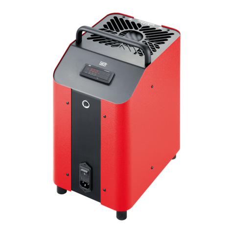
SIKA TP 18 600 E User manual

ba_tp18600e_e.doc/03/04/e Version 0.2Page 1
Operating instruction
Temperature calibrator TP 18 600 E
List of contents Page
1 Description of the temperature calibrator TP 18 600 E.......................................................................................2
2 Safty instructions.................................................................................................................................................2
3 Operation of the calibrator...................................................................................................................................4
3.1 Adjustment of the handle .................................................................................................................................4
3.2 Operating position............................................................................................................................................4
3.3 Adapter sleeves................................................................................................................................................4
3.4 Control of temperature sensors........................................................................................................................4
3.5 Front panel description.....................................................................................................................................4
3.6 Switching on of the calibrator...........................................................................................................................5
3.7 Indication of the block temperature and set temperature ................................................................................5
3.8 Adjustment of the block temperature...............................................................................................................5
3.9 Programming of the set point...........................................................................................................................6
4 Cooling down the heating block..........................................................................................................................6
5 Recalibration .......................................................................................................................................................6
6 Error signalling ....................................................................................................................................................6
7 Cleaning..............................................................................................................................................................6
8 Disposal...............................................................................................................................................................7
9 Guarantee and repairs........................................................................................................................................7
10 Technical Data ..................................................................................................................................................7

ba_tp18600e_e.doc/03/04/e Version 0.2Page 2
1 Description of the temperature calibrator TP 18 600 E
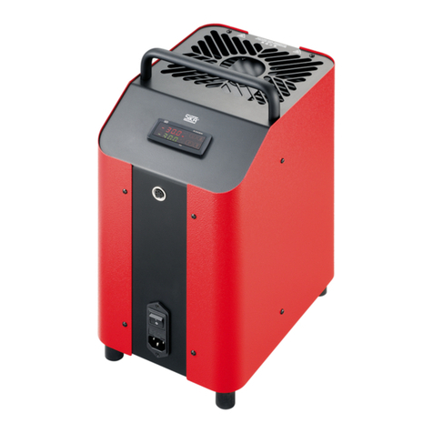
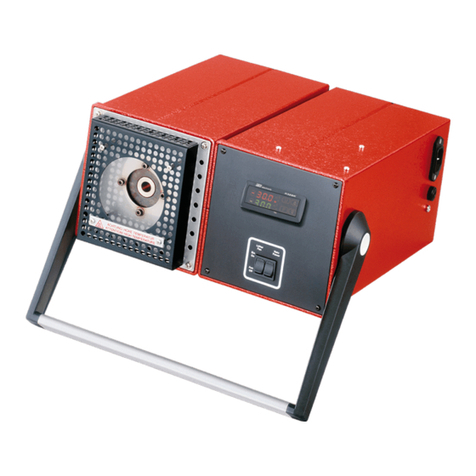
The test instrument TP 18600E consists of two single
enclosures, front size 144 x 144 mm and depth
340 mm or 390 mm. They are connected with each other
and equipped with a portable handle.
The left enclosure contains a brass block with a bore,
diameter 18 mm (28 mm) and depth 100 mm
(200 mm), which can be reached from the top, for the
reception of the test piece. In this block the heating
cartridge and the temperature sensor for the
determination of the block temperature are installed
accessible from the bottom.
The right enclosure contains the controller for control of
the block temperature. A Solid state relais is used for the
activation of the heating catridge.
On the front plate ist the controller, a switch for mains
power and also a switch for fan. The controller is
equipped with a 2-line, 4-digit, 7-segment LED for block
temperature and set value.
On the right hand side of the instrument combination the
IEC chassis mounting plug for the mains connection is
available. Besides the mains power cable the fuse holder
is located.
2 Safty instructions
The temperature calibrators of series TP 18.600 E correspond to the current state of technology. This refers to
measuring accuracy, function as well as safe operation of the devices. To grant safe operation, competent and
responsible behaviour of the operator is essential.
Fundamental safety regulation and operators duty of care
•Operate the equipment only in perfect functional conditions
•The national rules of safety and prevention of accidents have to be carefully observed as well as the
following safety notes of this manual.
•The equipment is supplied via mains cables with a tension dangerous for humans.
Person injuries can arise by inappropriate use.
•The perfect and safe operation of this equipment requires appropiate transport, professional storage,
installation, assembly and use as directed, as well as careful operation and maintenance.
•The equipment must only be used as directed. Furthermore dangerous media must not be used and all
specifications have to be kept.
•If disturbances can not be eliminated the equipment immediately is to be set out of operation and to be
protected from inadvertent start-up.
•Only the manufacturer is permitted to carry out repair works. Interferences or changes at the equipment
are inadmissible.
•Before exchanging the fuse, the equipment is to be seperated from the mains supply by pulling the cable
from the mains plug.
•Make this manual always availabe in a legible and complete form in situ of the equipment.

ba_tp18600e_e.doc/03/04/e Version 0.2Page 3
•Make shure that the operator of the equipment is instructed regularly in all applicable questions of
industrial safety and environmental protection, as well as is acquainted with the operating instructions, in
particular with the mentioned safety notes.
•Temperature fuse
For safety reasons the instrument has a temperature fuse for switching off the power for the heating if the
temperature of the heating block is above 620 °C. After cooling down the heating block the unit is ready
for working as before.
•The instrument has been projected and manufactured as a measuring and control device to be used
according to EN61010-1 for the altitudes operation until 2000 m.
The use of the instrument for applications not expressly permitted by the above mentioned rule must
adopt all the necessary protective measures.
•The instrument CANNOT be used in dangerous environments (flammable or explosive) without
adequate protection.
•The installer must ensure that EMC rules are respected, also after the instrument installation, if necessary
using proper filters.
•Whenever a failure or a malfunction of the device may cause dangerous situations for persons, thing or
animals, please remember that the plant has to be equipped with additional devices which will guarantee
safety.
•Attention: Danger of burning (block and test piece).
Before transportation or touching the heating block the block has to be cooled down.
If you should have any problems or questions, please contact your local supplier or directly:
SIKA – Dr. Siebert & Kühn GmbH & Co.KG
Struthweg 7-9
D-34260 Kaufungen
Tel ( 05605 ) 803-0
Fax ( 05605 ) 803-54
eMail: [email protected]
Internet: www.sika.net

ba_tp18600e_e.doc/03/04/e Version 0.2Page 4
3 Operation of the calibrator
The test instrument TP 18600 E is a portable unit for service purposes, as well as for operating and laboratory
tasks.
3.1 Adjustment of the handle
The handle can be adjusted into any required position from vertical to horizontal by pressing the lateral stop
buttons.
3.2 Operating position
To guarantee an optimal temperature distribution in the heating block, the normal operating position for the
instrument is the upright position
3.3 Adapter sleeves
It has to be made sure that the heat transmission resistance between the heating block and the test piece
(thermometer, temperature sensor, temperature switch) is as low as possible. Therefore it is necessary to use
exactly adapted pockets. The right bore is the outer dameter of the device under test + 0.5 mm.
3.4 Control of temperature sensors
For the test of temperature sensors a separate temperature measuring unit is required for the connection of the
test piece. By comparing the temperature of the external measuring unit with the block temperature you get an
information about the status of the test piece. Please note that it takes a short time until the test piece has
accepted the temperature of the block.
3.5 Front panel description
1 - Key P
This is used to access set point of the heating block and to confirm the selection.
2 - Key DOWN
This is used to decrease the values of the heating block
3 - Key UP
This is used to increase the values of the heating block
4 - Key U
no function for temeprature calibrator
5 - Led OUT1
indicates the state of output for heating block
6 - Led OUT2
indicates the state of output for temperature fuse

ba_tp18600e_e.doc/03/04/e Version 0.2Page 5
7 - Led SET
no function for temeprature calibrator
8 - Led AT/ST
no function for temeprature calibrator
9 – Display PV
It normally indicates the temperature of the heating block.
During programming it indicates SP1 (Set Point 1)
10 - Display SV
It normally indicates the active Set value of the heating block
3.6 Switching on of the calibrator
⇒⇒ After connection with the mains the fan starts immidiatly.
⇒⇒ After switching on the mains power switch the controller starts with initialisation.
The upper display (PV) indicates tESt.
The lower display indicates the actual version of the controller e.a. rL 1.2
After 5 sec. the initialisation is complete and the standard mode is selected automatically.
The upper display (PV) indicates the actual heating block temperature
The lower display (SV) indicates the actual set value of the heating block
The installed electrical heating cartridge heats the brass block up from ambient temperature to the adjusted set
point value.
3.7 Indication of the block temperature and set temperature
The red, 4-digit, 7-segment LED (PV) shows continuously the temperature of the heating block. If the, in the
green , 4-digit, 7-segment LED (SV), adjusted set temperature in the heating block is reached, the heating
energy radiated from the block is dispensed by short switching-on pulses of the heating cartridge, so that the
temperature inside of the block is kept constant.
3.8 Adjustment of the block temperature
The switch-on time of the heating is indicated by the red LED OUT1.
While during the heating-up period a permanent light shows the supply of heating energy. The flashing of the
LED shows that the temperature of the heating block is close to the adjusted set temperature, and therefore the
heating energy is now only supplied in short intervalls.
The control is carried out as a PID control.
In order to obtain good stability of the temperature, the cycle time “tcr1” has a low value with a very frequent
intervention of the control output.

ba_tp18600e_e.doc/03/04/e Version 0.2Page 6
3.9 Programming of the set point
⇒⇒ Push key P, then release it. The programming mode is activated.
The upper display (PV) will visualise “SP 1” (Set Popint 1).
The lower display (SV) will indicate the actual programmed value of the heating block.
⇒⇒ To modify the value, press 5key to increase the value of the heating block
⇒⇒ To modifythe value, press 6key to decrease the value of the heating block
⇒⇒ Once the desired value has been reached, by pushing key P it is possible to exit the programming mode.
NOTE:
A) The keys 5and 6change the value 1°C at a time but if they are pressed for more than one second, the
value increases or decreases rapidly and, after two seconds in the same condition, the changing speed
increases in order to allow the desired value to be reached rapidly.
B) If no key is pressed for approx. 15 seconds, the display will return to normal functioning automatically.
4 Cooling down the heating block
Attention: Danger of burning (block and test piece).
Before transportation or touching the heating block the block has to be cooled down.
After switching on the instrument the installed fan starts to produce cool air, which leads to a sufficient thermic
decoupling of the enclosure.
For a quicker colling down of the heating block the fan can be switched to position 2 (S2) to produce a higher
amount of cooling air.
5 Recalibration
The test instrument, series TP18000E , have been adjusted and checked before delivery with measuring means,
which are based on nationally accepted standards.
Due to the DIN ISO 10 012 the instruments have to be checked depending on the area of application in
adequate periodical intervals. We recommend to send us the instruments in intervals of 12 months at the latest
or approx. 500 working hours to our plant for recalibration or readjustment.
6Error signalling
Error Reason Action
- - - - Probe interrupted
uuuu The measured variable is under the probe’s
limits (under-range)
oooo The measured variable is over the probe’s limits
(over-range)
Verify the correct connection between probe
and instrument and then verify the correct
functioning of the probe
ErEP Possible anomaly of the EEPROM memory Push key “P”
In error conditions, the controller switches off the heating elements of the calibrator
7 Cleaning
We recommend cleaning of the instrument with a slightly wet cloth using water and not abrasive cleaners or
solvents which may damage the instrument.

ba_tp18600e_e.doc/03/04/e Version 0.2Page 7
8 Disposal
Company SIKA Dr Siebert & Kühn GmbH und Co.KG provides for an adequate disposal of used temperature
calibrators. For that purpose please send calibrators of series TP 18 600 E back to us freightfree.
9 Guarantee and repairs
The calibrator is under warranty against manufacturing flaws or faulty material, that are found within 12 months
from delivery date. The guarantee is limited to repairs or to the replacement of the instrument.
The eventual opening of the housing, the violation of the instrument or the improper use and installation of the
product will bring about the immediate withdrawal of the warranty’s effects.
In the event of a faulty instrument, either within the period of warranty, or further to its expiry, please contact our
sales department to obtain authorisation for sending the instrument to our company.
The faulty product must be shipped to SIKA with a detailed description of the faults found, without any fees or
charge for SIKA, except in the event of alternative agreements.
10 Technical Data
Regulation of the heating block with PID-regulator
Adjustment of the block temperature with key „P“, 5and 6in 1°C steps
automatic fine adjustment (auto. reset)
Adjustment range of the block temperature between ambient temperature and 600 °C
Stability of the block temperature +/- 0.5 K
Accuracy of the temperature indication +/- 1 K
Accuracy of block temperature +/- 0.5 K
Behavior in case of overtemperature temperature fuse switches off the power of the
heating block above 620 °C (hysteresys 1K)
Behavior in case of sensor break switch off of the heating
Heating times: Cooling times:
20 °C to 100 °C 2 min. 600 °C to 500 °C 6 min.
100 °C to 200 °C 3 min. 500 °C to 400 °C 8 min.
200 °C to 300 °C 4 min. 400 °C to 300 °C 11 min.
300 °C to 400 °C 5 min. 300 °C to 200 °C 15 min.
400 °C to 500 °C 6 min. 200 °C to 100 °C 32 min.
500 °C to 600 °C 7 min.
Heating block temperature indication (PV) red, 4-digit, 7-segment LED, 7mm high
Set point indication of heating block (SV) green, 4-digit, 7-segment LED, 7mm high
Range of indication 0 to 600 °C resolution 1K
Indication of sensor break - - -
Sampling rate: 130 msec.

ba_tp18600e_e.doc/03/04/e Version 0.2Page 8
Outputs 1 x relay SPDT (8 A-AC1, 3 A-AC3 / 250 VAC)
temperature fuse, 100.000 switches
1 x SSR drive (8mA/ 8VDC) control output
Power supply 230 V 50/60 Hz (optional 115 V 50/60 HZ)
Power consumption approx. 1300 VA
Fuse 6.3 A T (230VAC)
12.6 A T (115VAC)
Operating temperature 0 ... 50 °C
Operating humidity 30 ... 95 RH% without condensation
Storage temperature -10 ... +60 °C
Compliance: ECC directive EMC 89/336 (EN 61326)
ECC directive LV 73/23 and 93/68 (EN 61010-1)
Dimensions TP18600E TP18600/28E TP18600/200E TP18600/28/200E
heating block
bore ∅18 mm ∅28 mm ∅18 mm ∅28 mm
depths 100 mm 100 mm 200 mm 200 mm
housing
wide app. 310 mm app. 310 mm app. 310 mm app. 310 mm
high app. 144 mm app. 144 mm app. 144 mm app. 144 mm
deep app. 340 mm app. 340 mm app. 390 mm app. 390 mm
weight app. 9 kg app. 9 kg app. 12 kg app. 12 kg
adapter sleeves for smaller ∅available from 1.5 mm up to 15.5 mm (25 mm) ∅in steps of 0.5 mm
Table of contents
Other SIKA Measuring Instrument manuals
SIKA
SIKA VE Series User manual

SIKA
SIKA MH3111 User manual

SIKA
SIKA TP 17 *** M Series User manual
SIKA
SIKA Type E User manual

SIKA
SIKA TP 17 *** M Series User manual

SIKA
SIKA E2 User manual

SIKA
SIKA VO VA Series User manual

SIKA
SIKA Idroscan User manual

SIKA
SIKA TP 38 Series User manual

SIKA
SIKA E2 User manual

SIKA
SIKA MH3160-07 User manual

SIKA
SIKA Type Q User manual

SIKA
SIKA TP 28 1300 E Series User manual

SIKA
SIKA TD 32500 User manual

SIKA
SIKA TP 18 850 E User manual

SIKA
SIKA TP 18 200 E User manual

SIKA
SIKA TP 37166E.2 User manual

SIKA
SIKA E2 User manual

SIKA
SIKA TP37 series User manual
SIKA
SIKA TP 17165M User manual