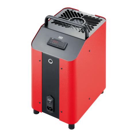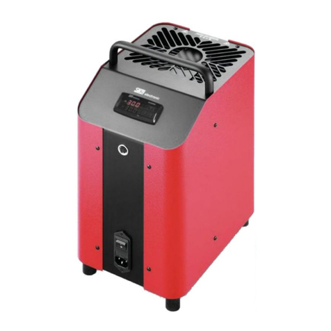
1 Instrument description and intended use TP 38 … / TP 38 … E
Subject to technical changes 2 Ba_TP38-E_en 12/2014
SIKA
Dr.Siebert
&
Kühn
GmbH
&
C
o.KG
Struthweg 7–9 D-34260 Kaufungen +49 5605 803-0 +49 5605 803-54 [email protected] www.SIKA.net Contents
1 Instrument description and intended use ........................................................................................................3
2 Safety instructions ...........................................................................................................................................4
2.1 Qualified personnel...............................................................................................................................4
2.2 Basic safety regulations........................................................................................................................4
2.3 Safety instructions for TP 38 … / TP 38 … E .......................................................................................4
2.4 Ground wire monitoring (TP 38 650 and TP 38 650 E)........................................................................5
3 Unpacking and inspecting the delivery............................................................................................................6
4 Structure of the temperature calibrator............................................................................................................6
4.1 Overview of components ......................................................................................................................6
4.2 The control panel..................................................................................................................................7
4.3 The metal calibration block...................................................................................................................8
4.4 Integrated measuring instrument..........................................................................................................8
4.5 PC connection, power switch and type label........................................................................................9
4.6 Components of the calibrator bottom..................................................................................................10
4.7 Warnings used....................................................................................................................................10
4.8 Accessories (included in the scope of delivery)..................................................................................11
4.9 Optional Accessories..........................................................................................................................11
4.10 DKD Calibration Certificate...............................................................................................................12
5 Commissioning of the calibrator....................................................................................................................13
5.1 Intended use .......................................................................................................................................13
5.2 Checks and activities prior to commissioning.....................................................................................13
5.3 Start procedure with TP 38 650 / TP 38 650 E...................................................................................14
6 Operation of the calibrator............................................................................................................................15
6.1 Description of the controls ..................................................................................................................15
6.2 Starting the Calibrator.........................................................................................................................17
6.3 Description of the control mode..........................................................................................................18
6.5 Settings and Descriptions in Select Mode..........................................................................................22
6.6 Description of the switch test mode....................................................................................................35
6.7 Description of the step test mode .......................................................................................................36
7 Cooling of the block and replacing the insert ...............................................................................................37
7.1 Cooling of the block ............................................................................................................................37
7.2 Replacing the adaptor inserts.............................................................................................................37
8 Troubleshooting.............................................................................................................................................37
8.1 Replacing the Fuses...........................................................................................................................37
8.2 Eliminating Faults................................................................................................................................38
9 Recalibration and Adjustment........................................................................................................................38
10 Transport and Storage.................................................................................................................................39
11 Care and Maintenance................................................................................................................................39
12 Disposal.......................................................................................................................................................39
13 Technical Data............................................................................................................................................40
13.1 TP 38 165 / TP 38 165 E (-35 to 165 °C)..........................................................................................40
13.2 TP 38 650 / TP 38 650 E (Ambient Temperature up to 650 °C) ...................................................41
13.3 Heat-up and Cool-down times ..........................................................................................................42
13.4 Technical data of the sensor inputs..................................................................................................43
