Siko MB500 Operation manual

MSK5000R+MB500+MR500 Datum 24.06.2009 Art.Nr. 84973 Änd. Stand 194/09 1
MSK5000R
MB500
MR500
DEUTSCH
1. Gewährleistungshinweise
Lesen Sie vor der Montage und der Inbetriebnahme
dieses Dokument sorgfältig durch. Beachten Sie zu
Ihrer eigenen Sicherheit und der Betriebssicherheit
alle Warnungen und Hinweise.
Ihr Produkt hat unser Werk in geprüftem und be-
triebsbereitem Zustand verlassen. Für den Betrieb
gelten die angegeben Spezifikationen und die
Angaben auf dem Typenschild als Bedingung.
Garantieansprüche gelten nur für Produkte der
Firma SIKO GmbH. Bei dem Einsatz in Verbindung
mit Fremdprodukten besteht für das Gesamtsystem
kein Garantieanspruch.
Reparaturen dürfen nur im Werk vorgenommen
werden. Für weitere Fragen steht Ihnen die Firma
SIKO GmbH gerne zur Verfügung.
2. Identifikation
Magnetband: Das Magnetband ist durch eine fort-
laufende Bedruckung identifizierbar.
•
•
•
•
z.B. XXXXXXXX-0023
Varianten-Nr.
Geräte-Typ
3. Mechanische Montage
Die Montage darf nur gemäß der angegebenen IP-
Schutzart vorgenommen werden. Das System muss
ggfs. zusätzlich gegen schädliche Umwelteinflüs-
se, wie z.B. Spritzwasser, Lösungsmittel, Staub,
Schläge, Vibrationen, starke Temperaturschwan-
kungen geschützt werden.
3.1 Montage Magnetband
Die Montage muss plan zur Montagefläche bzw. der
zu messenden Strecke erfolgen. Welligkeiten ver-
schlechtern immer die Messgenauigkeit.
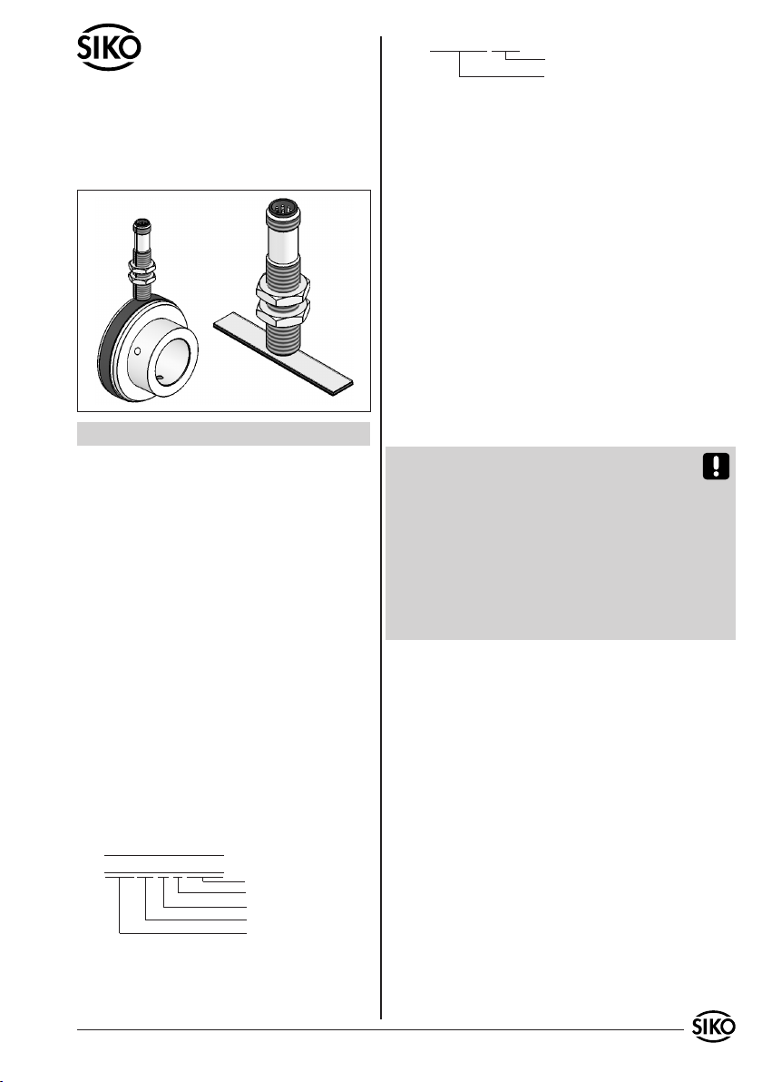
Überall wo aufgrund unzureichender Befestigungsmöglichkeiten
keine geeignete Montage des Magnetbandes möglich ist, kann das
Magnetband in eine als Zubehör lieferbare Profilschiene (z.B. Typ
PS oder PS1) montiert werden. Dadurch entsteht eine kompakte
Magnetbandeinheit.
Aus technischen Gründen muss bei der Länge,
gegenüber der Messstrecke, ein Zumaß von min.
32mm berücksichtigt werden.
Achtung! Um optimale Verklebungen zu errei-
chen müssen alle antiadhäsiven Fremdsubstanzen
(Öl, Fett, Staub usw.) durch möglichst rückstands-
los verdunstende Reinigungsmittel entfernt wer-
den. Als Reinigungsmittel eignen sich u.a. Ketone
(Aceton) oder Alkohole, die u.a. von den Firmen
Loctite und 3M als Schnellreiniger angeboten wer-
den. Die Klebeflächen müssen trocken sein und es
ist mit höchstmöglichem Anpreßdruck zu verkle-
ben. Die Verklebungstemperatur ist optimal zwi-
schen 20°C und 30°C in trockenen Räumen.
Tip! Bei Verklebung langer Bänder sollte die
Schutzfolie des Klebebandes über eine kurze Teil-
strecke abgezogen werden, um das Band zu fixie-
ren. Daraufhin erfolgt das Ausrichten des Bandes.
Nun kann über die restliche Länge die Schutzfolie,
unter gleichzeitigem Andruck des Bandes, seitlich
herausgezogen werden. (als Hilfsmittel kann eine
Tapetenandrückwalze verwendet werden)
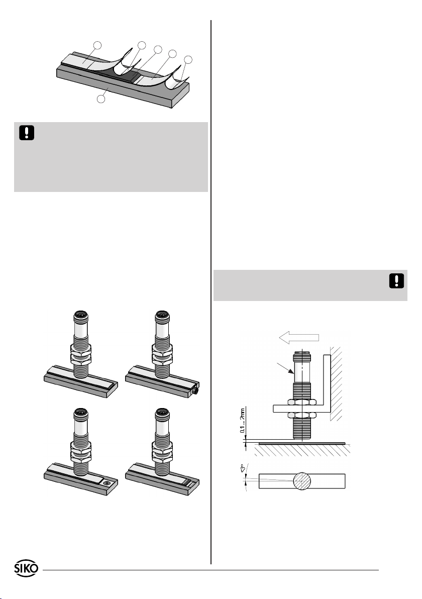
Montageschritte (Abb. 1)
Befestigungsfläche (1) sorgfältig reinigen.
Am Magnetband die Schutzfolie (2) des Klebe-
bandes (3) entfernen.
Magnetband (4) aufkleben.
Magnetbandoberfläche sorgfältig reinigen.
Am Abdeckband (5) die Schutzfolie (6) des Kle-
bebandes entfernen.
Abdeckband aufkleben (an beiden Enden leicht
überlappen lassen).
•
•
•
•
•
•
Benutzerinformation
MSK5000R Magnetsensor
MB500 Magnetband
MR500 Magnetring
Chargennummer
Referenzpunkt
Werkstoff-Trägerband
Genauigkeit
MB Typ
MB500 GEK WT RP NNNNNN
Magnetsensor, Magnetring: Das Typenschild zeigt
den Gerätetyp mit Variantennummer. Die Lieferpa-
piere ordnen jeder Variantennummer eine detail-
lierte Bestellbezeichnung zu.

2 MSK5000R+MB500+MR500 Datum 24.06.2009 Art.Nr. 84973 Änd. Stand 194/09
Abb. 2 Abb. 3
Abb. 4 Abb. 5
Abb. 6: Definition der Zählrichtung mit Magnetband
und Montage Sensor/Magnetband, Abstandsmaße,
Toleranzen
Verfahrrichtung
Laser-Markierung
Signal
A vor B
Abb. 1: Montage Magnetband
2
1
3
4
5 6
vorzusehen.
Der Magnetring MR500 muss möglichst kraft-
und spannungsfrei montiert werden. Eventuell
erforderliche Belastungen sind am Metallflansch
aufzubringen. Schläge auf den Magnetring sind
zu vermeiden.
Ein Wellenfreistich entsprechend Abb. 7 wird
empfohlen.
3.3 Montage Magnetsensor MSK5000R
Der Magnetsensor MSK5000R kann durch Verwen-
dung von 2 Schrauben M3 über die Langlöcher
befestigt werden. Es wird empfohlen die beilie-
genden Befestigungsschrauben und Federringe zu
verwenden.
Kabel sind so zu verlegen, dass keine Beschä-
digungsgefahr besteht. Zugentlastung und
wenn nötig Schleppkette oder Schutzschlauch
vorsehen.
Auf richtige Ausrichtung bezüglich der Zählrich-
tung achten (Abb. 6+7). Dies ist unerheblich
falls sich die Zählrichtung in der elektronischen
Auswertung umkehren läßt. (wie z.B. bei den
Magnetbandanzeigen von SIKO)
Achtung! Die Toleranz- und Abstandsmaße müs-
sen über die gesamte Messstrecke eingehalten
werden.
Anwendung LINEAR MSK5000R mit MB500:
•
•
•
•
Achtung! Die Beeinflussung durch magnetische
Felder ist zu vermeiden. Insbesondere dürfen keine
Magnetfelder (z.B. Haftmagnete oder andere Dau-
ermagnete) in direkten Kontakt mit dem Magnet-
band geraten. In stromlosem Zustand werden Be-
wegungen oder Verstellungen des Magnetsensors
von der Folgeelektronik nicht erkannt und erfasst.
Montagebeispiele
Die einfache Montageart, durch angeschrägtes
Schutzband (Abb. 2), ist nur in sehr geschützter
Umgebung zu empfehlen. Bei ungeschützer Um-
gebung besteht Abschälgefahr. In solchen Fällen
sind Montagearten, wie in Abb. 3 und 4 gezeigt,
geeigneter.
Den optimalen Schutz bietet die Montage in ei-
ner Nut (Abb. 5), die so tief sein sollte, dass das
Magnetband vollständig darin eingebettet werden
kann.
Die überlappenden Enden des Abdeckbandes gegen
Ablösen sichern.
•
3.2 Montage Magnetring MR500
Nach dem Aufschieben des Magnetringes auf die
Welle, wird durch Anziehen des Gewindestiftes M6
der MR500 mit der Welle verbunden.
Zwischen Welle und dem MR500 ist ein Schiebesitz •

MSK5000R+MB500+MR500 Datum 24.06.2009 Art.Nr. 84973 Änd. Stand 194/09 3
Abb.7: Definition der Zählrichtung mit Magnetring
und Montage Sensor / Magnetring, Abstandsmaße,
Toleranzen
Freistich an
der Vollwelle
für Gewin-
destift wird
empfohlen
Signal
A vor B Drehrichtung Magnetring
Laser-
Markierung
Ansichtseite =
Steckseite
Stiftkontakt
5-pol.
8-pol.
Anwendung RADIAL MSK5000R mit MR500:vorzusehen. Leitungsführungen parallel zu Ener-
gieleitungen vermeiden.
Schützspulen müssen mit Funkenlöschgliedern
beschaltet sein.
Spannungsversorgung
Die Spannungswerte sind abhängig von der Sen-
sorausführung und sind den Lieferpapieren sowie
dem Typenschild zu entnehmen.
z.B.: 5VDC
4.1 Anschlussbelegung
Anschluss mit Stecker M12.
Signal nicht
invertiert invertiert
I Pin 5 Pin 1
/I - - - 2
B 4 3
/B - - - 4
/A - - - 5
A 2 6
GND 3 7
+UB 1 8
5. Inbetriebnahme
Nach ordnungsgemäßer Montage und Verdrahtung
kann das Messsystem durch Einschalten der Versor-
gungsspannung in Betrieb genommen werden.
Das Messsystem MSK5000R/MB500/MR500 ist Be-
standteil eines inkrementalen Messsystem, dass
zur absoluten Messung an einer definierten Stelle
(Referenzpunkt) referenziert werden muss. Dazu
muss das Referenzsignal mit dem Signal eines Refe-
renzwertgebers (z.B. Näherungsschalter) verknüpft
werden.
6. Verfahrgeschwindigkeiten (m/s)
Auflösung in µm
Pulsabstand
(µs)
Zählfre-
quenz (kHz)
10 5
Verfahrgeschwindigkeit in m/s
20 20 0,12 2083,4
20 10 0,29 862,1
10 5 0,48 520,84
6,5 3,25 1 250
3 1,54 2 125
1,5 0,75 4 62,5
0,75 0,375 8 31,25
0,395 0,195 16 15,625
0,26 0,13 24 10,42
•
4. Elektrischer Anschluss
Verdrahtungsarbeiten dürfen nur spannungslos
erfolgen!
Vor dem Einschalten sind alle Leitungsanschlüsse
und Steckverbindungen zu überprüfen.
Hinweise zur Störsicherheit
Alle Anschlüsse sind gegen äußere Störeinflüsse
geschützt. Der Einsatzort ist aber so zu wählen,
dass induktive oder kapazitive Störungen nicht
auf den Sensor oder dessen Anschlussleitung
einwirken können! Durch geeignete Kabelführung
und Verdrahtung können Störeinflüsse (z.B.von
Schaltnetzteilen, Motoren, getakteten Reglern
oder Schützen) vermindert werden.
Erforderliche Maßnahmen
Nur geschirmtes Kabel verwenden. Den Kabel-
schirm beidseitig auflegen. Litzenquerschnitt der
Leitungen min. 0,14mm²; max.0,5mm².
Die Verdrahtung von Abschirmung und Masse
(0V) muss sternförmig und großflächig erfolgen.
Der Anschluss der Abschirmung an den Potenti-
alausgleich muss großflächig (niederimpedant)
erfolgen.
Das System muss in möglichst großem Abstand von
Leitungen eingebaut werden, die mit Störungen
belastet sind; ggfs. sind zusätzliche Maßnahmen
wie Schirmbleche oder metallisierte Gehäuse
•
•
•
•
•

4 MSK5000R+MB500+MR500 Datum 24.06.2009 Art.Nr. 84973 Änd. Stand 194/09
7. Ausgangssignale
Die Auswerteelektronik setzt die magnetischen
Längeninformationen des Magnetsensors in in-
krementale Ausgangssignale um. Die Ausgabe der
Signale erfolgt geschwindigkeitsproportional.
Es ist zu beachten, dass im Stillstand Impulse
von der Breite des eingestellten Pulsabstandes
auftreten können (bedingt durch das interne In-
terpolationsverfahren).
Achtung! Bei der Dimensionierung der Nachfol-
geelektronik ist zu beachten, dass diese für den
eingestellten Pulsabstand bzw. Zählfrequenz aus-
gelegt ist.
Signalfolge
Der Sensor wurde nicht entsprechend Abb. 6+7
ausgerichtet.
•
Hinweis: Die Lage des Indexsignals I zu den Sig-
nalen A und B ist nicht definiert und kann von der
Zeichnung abweichen.
8. Wartung
Die Oberfläche des Magnetbandes ist bei starker
Verschmutzung durch Staub, Späne, Feuchtigkeit
usw., von Zeit zu Zeit mit einem weichen Lappen
zu reinigen.
9. Fehlerbehandlung
Typische Fehler, die bei Anbau und Betrieb auf-
treten:
Das Magnetband wurde falsch montiert / aktive
Seite nach unten.
Zum Schutz des Magnetbandes wurde nicht das
mitgelieferte Abdeckband verwendet. Das Abdeck-
band muss nicht magnetisierbar sein.
Der Sensor ist nicht, oder nicht korrekt ange-
schlossen (Pinbelegung Kap. 4.1)
Die Abstandstoleranz zwischen Sensor und Ma-
gnetband/Magnetring wurde nicht eingehalten
(beim Band über die gesamte Messstrecke!), der
Sensor streift auf dem Magnetring (Abb. 6+7).
Der Sensor ist mit der aktiven Seite vom Band
abgewandt montiert (Abb. 6+7).
•
•
•
•
•

MSK5000R+MB500+MR500 Datum 24.06.2009 Art.Nr. 84973 Änd. Stand 194/09 5
MSK5000R
MB500
MR500
ENGLISH
1. Warranty information
In order to carry out installation correctly, we
strongly recommend this document is read very
carefully. This will ensure your own safety and
the operating reliability of the device.
Your device has been quality controlled, tested
and is ready for use. Please observe all warnings
and information which are marked either directly
on the device or specified in this document.
Warranty can only be claimed for components
supplied by SIKO GmbH. If the system is used
together with other products, there is no warranty
for the complete system.
Repairs should be carried out only at our works.
If any information is missing or unclear, please
contact the SIKO sales staff.
2. Identification
Magnetic strip: identification by printing on the
strip.
•
•
•
•
eg. XXXXXXXX-0023
version number
type of unit
3. Installation
For mounting, the degree of protection specified
must be observed. If necessary, protect the unit
against environmental influences such as sprayed
water, dust, knocks, extreme temperatures.
3.1 Mounting the magnetic strip
The mounting surface / measuring track must be
flat. Buckles or bumps will lead to measuring in-
accuracies.
For applications which do not allow properly glueing of the magne-
tic strip, it can be inserted into a profile rail (accessory) - eg. rail
type PS or PS1 thus forming a compact mounting unit.
For technical reasons the strip should be min.
32mm longer than the actual measuring distance.
Attention! To guarantee optimal adhesion oil,
grease dust etc. must be removed by using clean-
sing agents which evaporate without leaving re-
sidues. Suitable cleansing agents are eg. ketones
(acetone) or alcohols; Messrs. Loctite and 3M can
both supply such cleansing liquid. Make sure that
the surface to be glued is dry and apply the strip
with maximum pressure. Glueing should preferably
be undertaken at temperatures between 20°C to
30°C and in dry atmosphere.
Advice! Wh en applying long pieces of magnetic
strip do not immediately remove the complete pro-
tective foil, but rather peel back a short part from
the end sufficient to fix the strip. Now align the
strip. As the protective strip is then peeled back
and out press the tape firmly onto the mounting
surface. A wall paper roller wheel could be used to
assist in applying pressure onto the magnetic strip
when fixing it in position.
Mounting steps (see fig. 1)
Clean mounting surface (1) carefully.
Remove protective foil (2) from the adhesive
side of the magnetic strip (3).
Stick down the magnetic strip (4).
Clean surface of magnetic strip carefully.
Remove protective foil (6) from adhesive tape on
the cover strip (5).
Fix cover strip (both ends should slightly over-
lap).
Also fix cover strip’s ends to avoid unintenti-
onal peeling.
•
•
•
•
•
•
•
User Information
MSK5000R Magnetic sensor
MB500 Magnetic strip
MR500 Magnetic ring
Magnetic sensor, magnetic ring: Please check
the particular type of unit and type number from
the identification plate. Type number and the cor-
responding version are indicated in the delivery
documentation.
batch number
reference point
material carrier strip
accuracy
MB type
MB500 GEK WT RP NNNNNN

6 MSK5000R+MB500+MR500 Datum 24.06.2009 Art.Nr. 84973 Änd. Stand 194/09
Fig. 2 Fig. 3
Fig. 4 Fig. 5
Fig. 1: Mounting of the magnetic strip
2
1
3
4
5 6
Fig. 6: Definition of the counting direction with
magnetic strip and assemblage sensor/magnetic ring,
gap measure, tolerances
Travel direction
Signal
A before B
Laser marking
Attention! Do not expose the system to magne-
tic fields. Any direct contact of the magnetic strip
with magnetic fields (eg. adhesive magnets or
other permanent magnets) is to be avoided. Sen-
sor movements during power loss are not captured
by the follower electronics.
Mounting examples
Mounting with chamfered ends (fig. 2) is not re-
commended unless the strip is installed in a safe
and protected place without environmental influ-
ences. In less protected mounting places the strip
may peel. There we recommend mounting accord.
to fig. 3 and 4.
Mounting in a groove (fig. 5) best protects the
magnetic strip. The groove should be deep enough
to totally embed the magnetic strip.
3.3 Mounting of the magnetic sensor MSK5000R
The magnetic sensor MSK5000R can be fastened by
using two bolts M3 over the elongated holes. We
recommend to use the enclosed fixing screws and
washer springs.
Cables should be layed in such a way that there
is no danger of damaging. Provide ten-sion relief
and drag chain or casing, if neces-sary.
Observe the correct alignment with regard to the
counting direction (fig. 6 and 7). This does not
apply if the counting direction can be reversed
in the electronic interpretation. (e.g. in SIKO's
magnetic-strip displays)
Attention! The tolerance and gap measures must
be observed over the whole measuring length.
LINEAR application MSK5000R with MB500:
•
•
3.2 Mounting of the magnetic ring MR500
Slide magnetic ring MR500 onto the shaft and
then tighten grub screw M6 to fix it to the shaft.
Ensure sliding fit between shaft and MR500.
Mount MR500 without force and without strain.
Possible forces should go to the metal flange.
Avoid knocks on the magnetic ring.
Provide for a relief groove in the solid shaft
(see fig.7).
•
•
•

MSK5000R+MB500+MR500 Datum 24.06.2009 Art.Nr. 84973 Änd. Stand 194/09 7
Fig.7: Definition of the counting direction with ma-
gnetic ring and assemblage sensor/magnetic ring,
gap measure, tolerances
Undercut at
the solid shaft
for tread plug
is recommen-
ded
Signal
A before B Direction of rotation
of magnetic ring
Laser
marking
viewing side =
plug-in side
plug pin
5 pole
8 pole
RADIAL application MSK5000R with MR500:pression.
Supply voltage
The voltages depend on the sensor designs; they
are to be taken from the delivery documentation
and the identification plate.
eg.: 5VDC
4.1 Pin assignment
Connection with M12 plug.
Signal not
inverted inverted
I Pin 5 Pin 1
/I - - - 2
B 4 3
/B - - - 4
/A - - - 5
A 2 6
GND 3 7
+UB 1 8
5. Commissioning
Following proper installation and wiring, the
measuring system can be commissioned by
switching on the supply voltage.
The measuring system MSK5000/MB500TMR500 is
a component of an incremental measuring system
which must be referenced at a defined position
(reference point) for absolute measurement. For
this purpose, the reference signal must be linked
to the signal of a reference value encoder (e.g.,
proximity switch).
6. Travel speeds (m/s)
Resolution in µm
Pulse inter-
val (µs)
Counting
frequency
(kHz)
10 5
Travel speed in m/s
20 20 0,12 2083,4
20 10 0,29 862,1
10 5 0,48 520,84
6,5 3,25 1 250
3 1,54 2 125
1,5 0,75 4 62,5
0,75 0,375 8 31,25
0,395 0,195 16 15,625
0,26 0,13 24 10,42
4. Electrical connection
Wiring must only be carried out with power off!
Check all lines and connections before switching
on the equipment!
Interference and distortion
All connections are protected against the effects
of interference. The location should be selected
to ensure that no capacitive or inductive in-
terferences can affect the sensor or the con-
nection lines! Suitable wiring layout and choice
of cable can minimise the effects of interference
(eg. interference caused by SMPS, motors, cyclic
controls and contactors).
Necessary measures
Only screened cable should be used. Wire cross sec-
tion is to be at least 0,14mm², max. 0,5mm².
Wiring to the screen and ground (0V) must
be secured to a good point. Ensure that the
connection of the screen and earth is made to
a large surface area with a sound connection to
minimise impedance.
The system should be positioned well away from
cables with interference; if necessary a protective
screen or metal housing must be provided. The
running of wiring parallel to the mains supply
should be avoided.
Contactor coils must be linked with spark sup-
•
•
•
•
•
•

8 MSK5000R+MB500+MR500 Datum 24.06.2009 Art.Nr. 84973 Änd. Stand 194/09
Note: The position of the index signal I, respec-
tively, with respect to signals A and B is not defi-
ned and can deviate from the drawing.
8. Maintenance
We recommend cleaning the magnetic strip’s sur-
face from time to time with a soft rag. This avo-
ids dirt (dust, chips, humidity ...) sticking to the
strip.
9. Trouble shooting
Below are some typical errors which may occur du-
ring installation and operation:
Magnetic strip incorrectly mounted (active surface
must be mounted towards the sensor).
Use of foreign protective strip. Must always be
non-magnetic.
Sensor not or incorrectly connected (pin connec-
tion, see chapter 4.1).
Tolerance for the gap between magnetic sensor and
magnetic strip not observed over the total travel
distance. Sensor touches strip (see fig. 6+7).
Sensor’s active side not mounted towards the
magnetic strip (see fig. 6+7).
Sensor has not been aligned according to fig.
6+7.
•
•
•
•
•
•
7. Output signals
The translation module translates the length
information of the magnetic sensor into incre-
mental output signals with real-time processing of
the output signals.
Please note that pulses having the width of
the pulse interval set can occur at standstill of
the device (caused by the internal interpolation
method).
Caution! When dimensioning the follow-on elec-
tronics please take care that it is adjusted to the
set pulse interval or counting frequency, respec-
tively.
Signal sequence
SIKO GmbH
Werk / Factory:
Weihermattenweg 2
79256 Buchenbach-Unteribental
Postanschrift / Postal address:
Postfach 1106
79195 Kirchzarten
Telefon/Phone +49 7661 394-0
Telefax/Fax +49 7661 394-388
E-Mail info@siko.de
Internet www.siko.de
Service [email protected]e
Other manuals for MB500
1
This manual suits for next models
2
Table of contents
Languages:
Other Siko Accessories manuals