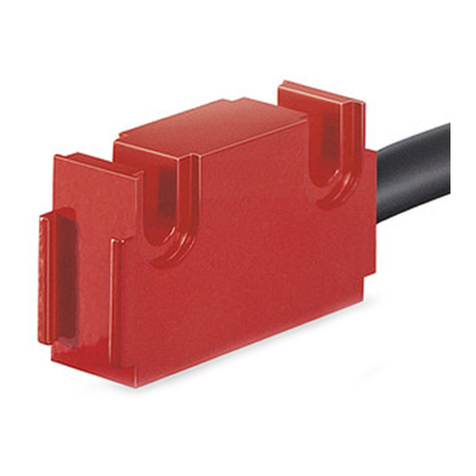
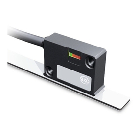
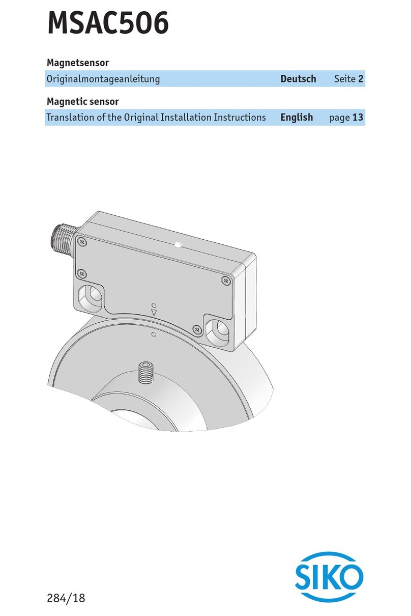
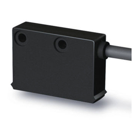
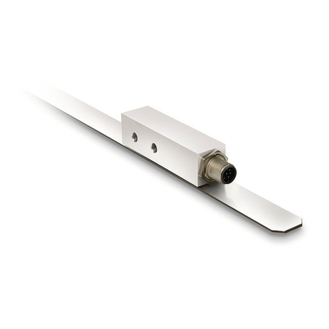
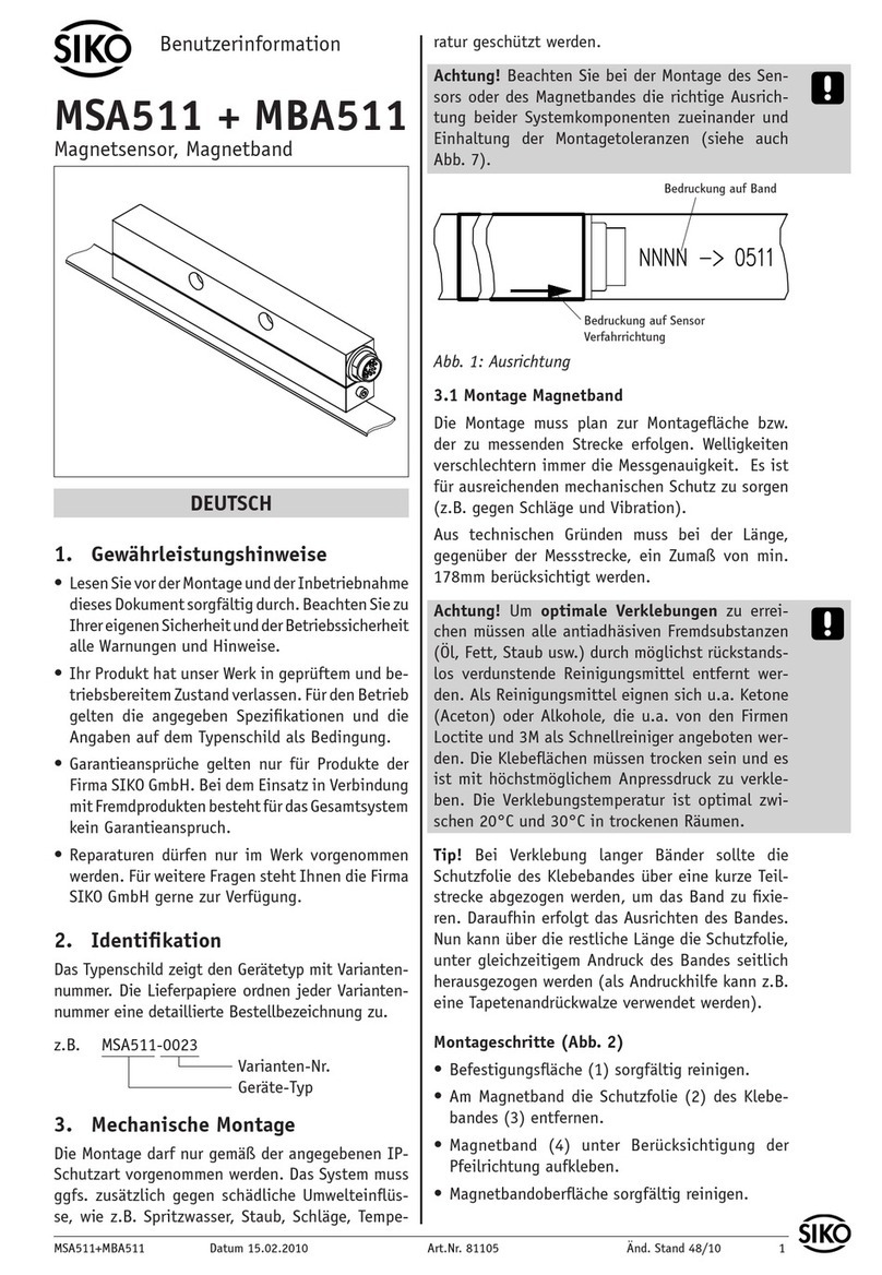
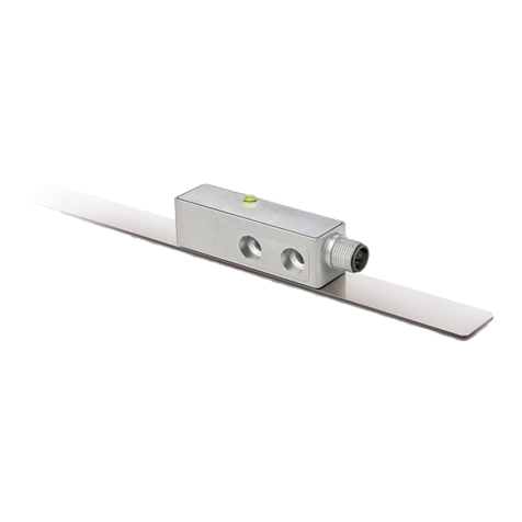
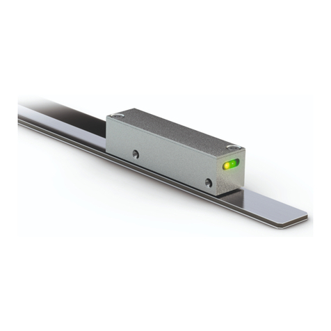
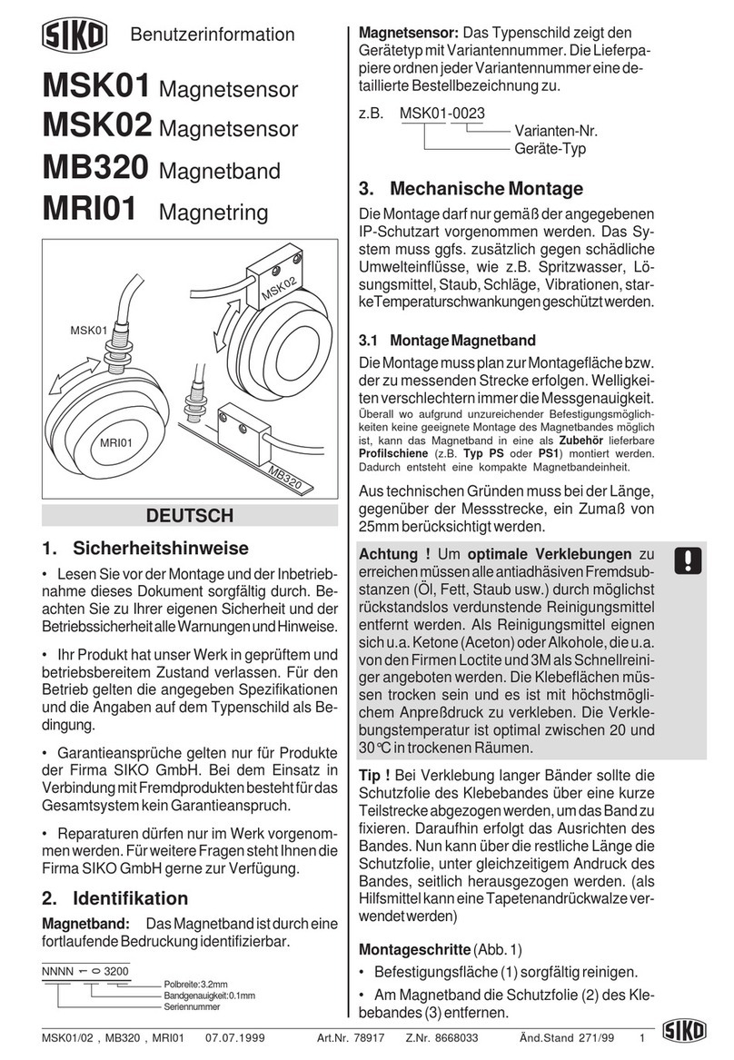
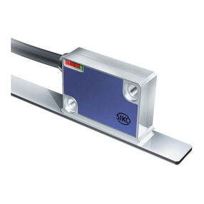
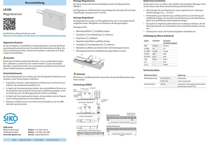
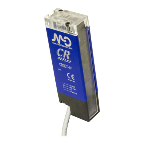
Siko MS100/1 User manual

MS100/1
Deutsch
MS100/1 · Datum 27.04.2018 · Art. Nr. 82106 · Änd. Stand 118/18
2
Inhaltsverzeichnis
1 Dokumentation . . . . . . . . . . . . . . . . . . . . 3
2 Sicherheitshinweise . . . . . . . . . . . . . . . . . . 3
2.1 Bestimmungsgemäße Verwendung . . . . . . . . . . . 3
2.2 Kennzeichnung von Gefahren und Hinweisen . . . . . . 3
2.3 Zielgruppe . . . . . . . . . . . . . . . . . . . . 4
2.4 Grundlegende Sicherheitshinweise . . . . . . . . . . . 4
3 Identifikation . . . . . . . . . . . . . . . . . . . . . 5
4 Installation . . . . . . . . . . . . . . . . . . . . . . 5
4.1 Mechanische Montage . . . . . . . . . . . . . . . . 5
4.2 Montage Magnetband . . . . . . . . . . . . . . . . 6
4.3 Montage Magnetsensor . . . . . . . . . . . . . . . 8
4.4 Elektrische Installation . . . . . . . . . . . . . . . 9
5 Inbetriebnahme . . . . . . . . . . . . . . . . . . . 10
6 Fehlerbehandlung . . . . . . . . . . . . . . . . . . 10
7 Transport, Lagerung, Wartung und Entsorgung . . . . . . 10
8 Technische Daten . . . . . . . . . . . . . . . . . . 11

MS100/1
Dokumentation Deutsch
MS100/1 · Datum 27.04.2018 · Art. Nr. 82106 · Änd. Stand 118/18
3
1 Dokumentation
Zu diesem Produkt gibt es folgende Dokumente:
• Datenblatt beschreibt die technischen Daten, die Abmaße, die
Anschlussbelegungen, das Zubehör und den Bestellschlüssel.
• Montageanleitung beschreibt die mechanische und die elektrische
Montage mit allen sicherheitsrelevanten Bedingungen und den dazu-
gehörigen technischen Vorgaben.
Diese Dokumente sind auch unter "http://www.siko-global.com/p/
ms100-1" zu finden.
2 Sicherheitshinweise
2.1 Bestimmungsgemäße Verwendung
Der Magnetsensor MS100/1 dient in Kombination mit dem Magnetband
MB100/1 der Ermittlung eines inkrementellen Positionswertes. Der Mag-
netsensor ist nur für die Verwendung im Industriebereich vorgesehen die
keinen besonderen elektrischen oder mechanischen Sicherheitsanforde-
rungen unterliegen.
1. Beachten Sie alle Sicherheitshinweise in dieser Anleitung.
2. Eigenmächtige Umbauten und Veränderungen an dem Magnetsensor
sind verboten.
3. Die vorgeschriebenen Betriebs- und Installationsbedingungen sind
einzuhalten.
4. Der Magnetsensor darf nur innerhalb der technischen Daten und der
angegebenen Grenzen betrieben werden (siehe Kapitel 8).
2.2 Kennzeichnung von Gefahren und Hinweisen
Sicherheitshinweise bestehen aus dem Signalzeichen und einem Signal-
wort.
Gefahrenklassen
Unmittelbare Gefährdungen, die zu schweren irreversiblen Körperverlet-
zungen mit Todesfolge, Sachschäden oder ungeplanten Gerätereaktionen
führen können, sofern Sie die gegebenen Anweisungen missachten.
Gefährdungen, die zu schweren Körperverletzungen, Sachschäden oder
ungeplanten Gerätereaktionen führen können, sofern Sie die gegebenen
Anweisungen missachten.
GEFAHR
WARNUNG

MS100/1
Sicherheitshinweise Deutsch
MS100/1 · Datum 27.04.2018 · Art. Nr. 82106 · Änd. Stand 118/18
4
Gefährdungen, die zu leichten Verletzungen, Sachschäden oder ungeplan-
ten Gerätereaktionen führen können, sofern Sie die gegebenen Anweisun-
gen missachten.
Wichtige Betriebshinweise, die die Bedienung erleichtern oder die bei
Nichtbeachtung zu ungeplanten Gerätereaktionen führen können und
somit möglicherweise zu Sachschäden führen können.
Signalzeichen
2.3 Zielgruppe
Montageanleitung wendet sich an das Projektierungs-, Inbetriebnahme-
und Montagepersonal von Anlagen- oder Maschinenherstellern, das
über besondere Kenntnisse innerhalb der Antriebstechnik verfügt. Die-
ser Personenkreis benötigt fundierte Kenntnisse über die notwendigen
Anschlüsse eines Magnetsensors und deren Integration in die komplette
Maschinenanlage.
Nicht ausreichend qualifiziertes Personal
Personenschäden, schwere Schäden an Maschine und Magnetsensor wer-
den durch nicht ausreichend qualifiziertes Personal verursacht.
`Projektierung, Inbetriebnahme, Montage und Wartung nur durch
geschultes Fachpersonal.
`Dieses Personal muss in der Lage sein, Gefahren, welche durch die
mechanische, elektrische oder elektronische Ausrüstung verursacht
werden können, zu erkennen.
Qualifiziertes Personal
sind Personen, die
• als Projektierungspersonal mit den Sicherheitsrichtlinien der Elektro-
und Automatisierungstechnik vertraut sind;
• als Inbetriebnahme- und Monatagepersonal berechtigt sind, Strom-
kreise und Geräte/Systeme gemäß den Standards der Sicherheitstech-
nik in Betrieb zu nehmen, zu erden und zu kennzeichnen.
2.4 Grundlegende Sicherheitshinweise
Explosionsgefahr
`Magnetsensor nicht in explosionsgefährdeten Zonen einsetzen.
VORSICHT
ACHTUNG
WARNUNG
GEFAHR

MS100/1
Identifikation Deutsch
MS100/1 · Datum 27.04.2018 · Art. Nr. 82106 · Änd. Stand 118/18
5
Bewegliche Teile
Quetschungen, Reibung, Abschürfen, Erfassen von Gliedmaßen und Klei-
dung durch Berühren von beweglichen Teile wie z. B. Sensor im Betrieb.
`Zugrismöglichkeit durch Schutzmaßnahmen verhindern.
Externe Magnetfelder
Es kommt zu Betriebsstörungen und Datenverlust, wenn starke externe
Magnetfelder das interne Messsystem beeinflussen.
`Schützen Sie den Magnetsensor vor Einflüssen von Fremdmagneten.
3 Identifikation
Das Typenschild zeigt den Gerätetyp mit Variantennummer. Die Lieferpa-
piere ordnen jeder Variantennummer eine detaillierte Bestellbezeichnung
zu.
z. B. MS100/1-0023
Varianten-Nr.
Geräte-Typ
Das Magnetband ist durch eine fortlaufende Bedruckung identifizierbar.
z. B. MBxxxx GEK WT RP NNNNNN
Chargennummer
Referenzpunkt
Werksto-Trägerband
Genauigkeit
MB Typ
4 Installation
4.1 Mechanische Montage
Ausfall Magnetsensor
`IP-Schutzart bei Montage beachten (siehe Kapitel 8).
`Magnetsensor nicht selbst önen.
`Schläge auf das Gerät vermeiden.
`Keinerlei Veränderung am Gerät vornehmen.
`Kabel mit Zugentlastung installieren. Wenn nötig Schleppkette oder
Schutzschlauch vorsehen.
GEFAHRWARNUNG
VORSICHT
VORSICHT

MS100/1
Installation Deutsch
MS100/1 · Datum 27.04.2018 · Art. Nr. 82106 · Änd. Stand 118/18
6
Verlust der Messwerte
`Toleranz- und Abstandsmaße über die gesamte Messstrecke einhalten.
Sensorabbildungen sind exemplarisch und gültig für alle Bauformen,
sofern nicht gesondert beschrieben.
4.2 Montage Magnetband
Externe Magnetfelder
Magnetisierung des Magnetbandes geht verloren. Insbesondere dürfen
keine Magnetfelder (z. B. Haftmagnete oder andere Dauermagnete) in
direkten Kontakt mit dem Magnetband geraten. In stromlosem Zustand
werden Bewegungen oder Verstellungen des Magnetsensors von der Fol-
geelektronik nicht erkannt und erfasst.
`Schützen Sie das Magnetband vor Einflüssen von Fremdmagneten.
Lösen Magnetbandverklebung
`Antiadhäsiven Fremdsubstanzen, wie Öl, Fett oder Staub, durch mög-
lichst rückstandsfrei verdunstende Reinigungsmittel entfernen. Geeig-
nete Reinigungsmittel sind unter anderem Ketone (Aceton) oder Alko-
hol, die z. B. von der Firma Loctite oder 3M als Schnellreiniger ange-
boten werden.
`Für eine optimale Verklebung müssen die Klebeflächen trocken sein
und es ist mit höchstmöglichem Anpressdruck zu verkleben.
`Verklebungstemperatur zwischen 20°C und 30°C in trockenen Räu-
men einhalten.
Verschlechterung Messgenauigkeit
`Magnetband plan zur Montageoberfläche beziehungsweise der mes-
senden Strecke montieren. Welligkeiten verschlechtern die Mess-
genauigkeit.
Länge Magnetband
`Aus technischen Gründen muss bei der Länge, gegenüber der Mess-
strecke, ein Zumaß von ≥47mm berücksichtigt werden.
Bei Verklebung langer Bänder sollte die Schutzfolie des Klebebandes über
eine kurze Teilstrecke abgezogen werden um das Band zu fixieren. Darauf-
hin erfolgt das Ausrichten des Bandes. Nun kann über die restliche Länge
die Schutzfolie, unter gleichzeitigem Andruck des Bandes, seitlich heraus-
gezogen werden (als Hilfsmittel kann eine Tapetenandrückwalze verwen-
det werden).
ACHTUNG
ACHTUNG
VORSICHT
ACHTUNG
ACHTUNG
ACHTUNG

MS100/1
Installation Deutsch
MS100/1 · Datum 27.04.2018 · Art. Nr. 82106 · Änd. Stand 118/18
7
Montage (Abb. 1):
1. Befestigungsfläche 1sorgfältig reinigen.
2. Schutzfolie 2des Klebebandes 3entfernen.
3. Magnetband 4aufkleben.
4. Magnetbandoberfläche sorgfältig reinigen.
5. Schutzfolie 6des Abdeckbandes 5entfernen.
6. Abdeckband aufkleben (an beiden Enden leicht überlappen lassen).
7. Überlappende Enden des Abdeckbandes gegen Ablösen sichern.
Abb. 1: Montage Magnetband
Montagebeispiele
Die einfache Montageart, durch angeschrägtes Magnetband wie in Abb.
2, ist nur in sehr geschützter Umgebung zu empfehlen. Bei ungeschützter
Umgebung besteht Abschälgefahr. In solchen Fällen sind Montagearten,
wie in Abb. 3 und Abb. 4 gezeigt, geeigneter.
Den optimalen Schutz bietet die Montage in einer Nut wie in Abb. 5. Diese
sollte so tief sein, dass das Magnetband vollständig darin eingebettet ist.
Abb. 2: Magnetband
angeschrägt
Abb. 3: Magnetband von vorne
verschraubt
Abb. 4: Magnetband von oben
verschraubt
Abb. 5: Magnetband in Nut

MS100/1
Installation Deutsch
MS100/1 · Datum 27.04.2018 · Art. Nr. 82106 · Änd. Stand 118/18
8
4.3 Montage Magnetsensor
Ausrichtung Magnetsensor
`Auf richtige Ausrichtung des Magnetsensors achten, damit die opti-
male Abtastung gewährleistet ist (siehe Abb. 6).
1. Magnetband montieren (siehe Kapitel 4.2).
2. Magnetsensor Bauform L kann durch Verwendung von 2 Schrauben M3
über die ø3.1mm Durchgangslöcher befestigt werden (Anzugsmoment
= 1Nm).
Magnetsensor Bauform B-TR kann durch Verwendung von 2 Schrau-
ben M2.5 über Sacklochgewinde befestigt werden (Anzugsmoment =
1Nm).
1Verfahrrichtung Sensor,
Zählrichtung negativ
2Kabelabgangsrichtung
Abb. 6: Definition der Zählrichtung
1aktive Seite Magnetband
2zulässige Abweichung Band/
Sensor
≤0.4mm
3maximale Fluchtungsfehler
Abb. 7: Montage Sensor/Magnetband, Abstandsmaße, Toleranzen
<1° <3°
<3°
ACHTUNG

MS100/1
Installation Deutsch
MS100/1 · Datum 27.04.2018 · Art. Nr. 82106 · Änd. Stand 118/18
9
4.4 Elektrische Installation
Zerstörung von Anlagenteilen und Verlust der Steuerungskontrolle
`Alle Leitungen für den Magnetsensor müssen geschirmt sein.
`Elektrische Verbindungen nicht unter Spannung anschließen oder
lösen.
`Verdrahtungsarbeiten spannungslos durchführen.
`Litzen mit geeigneten Aderendhülsen versehen.
`Die Verdrahtung von Abschirmung und Masse (0V) muss sternför-
mig und großflächig erfolgen. Der Anschluss der Abschirmung an den
Potentialausgleich muss großflächig (niederimpedant) erfolgen.
`Vor dem Einschalten sind alle Leitungsanschlüsse und Steckverbindun-
gen zu überprüfen.
`Betriebsspannung gemeinsam mit der Folgeelektronik (z. B. Steue-
rung) einschalten.
Alle Anschlüsse sind prinzipiell gegen äußere Störeinflüsse geschützt. Der
Einsatzort ist so zu wählen, dass induktive oder kapazitive Störungen nicht
auf den Magnetsensor oder dessen Anschlussleitungen einwirken können.
Das System in möglichst großem Abstand von Leitungen einbauen, die mit
Störungen belastet sind. Gegebenenfalls sind zusätzliche Maßnahmen,
wie Schirmbleche oder metallisierte Gehäuse vorzusehen. Schützspulen
müssen mit Funkenlöschgliedern beschaltet sein.
Anschluss
Dieser Magnetsensor ist vorbereitet zum Anschluss an eine SIKO-Messan-
zeige MA100/2 oder MA523/1. Der Sensoranschluss darf nicht verändert
werden (z. B. durch Kabelverlängerungen).
1. Stecker vor Anschlussbuchse in Position bringen.
2. Verriegelung 1des Steckers nach hinten ziehen.
3. Stecker bis an den Anschlag in die Anschlussbuchse einstecken.
4. Verriegelung 1loslassen.
1Verriegelung
(schwarzes
Kunststoteil)
1
Abb. 8: Anschluss
WARNUNG
ACHTUNG
ACHTUNG

MS100/1
Inbetriebnahme Deutsch
MS100/1 · Datum 27.04.2018 · Art. Nr. 82106 · Änd. Stand 118/18
10
5 Inbetriebnahme
Nach ordnungsgemäßer Montage und Verdrahtung kann das Messsystem
durch Einschalten der Betriebsspannung in Betrieb genommen werden.
6 Fehlerbehandlung
Typische Fehler, die bei Anbau und Betrieb auftreten:
• Magnetband ist falsch montiert, aktive Seite ist unten (siehe Kapitel
4.2).
• Zum Schutz des Magnetbandes wurde nicht das mitgelieferte Abdeck-
band verwendet. Das Abdeckband darf nicht magnetisierbar sein.
• Der Magnetsensor ist nicht, oder nicht korrekt angeschlossen.
• Die Abstandstoleranzen wurde nicht über die gesamte Messstrecke
eingehalten (siehe Abb. 7).
• Kabelunterbrechung/Abtrennung durch scharfe Kanten/Quetschung.
• Der Magnetsensor ist mit der aktiven Seite vom Band abgewandt mon-
tiert (siehe Abb. 7).
• Der Magnetsensor wurde nicht, entsprechend Abb. 7 ausgerichtet.
7 Transport, Lagerung, Wartung und Entsorgung
Transport und Lagerung
Magnetsensoren sorgfältig behandeln, transportieren und lagern. Hierzu
sind folgende Punkte zu beachten:
• Magnetsensoren in der ungeöneten Originalverpackung transportie-
ren und/oder lagern.
• Magnetsensoren vor schädlichen physikalischen Einflüssen wie Staub,
Hitze und Feuchtigkeit schützen.
• Anschlüsse weder durch mechanische noch durch thermische Einflüsse
beschädigen.
• Vor Montage ist der Magnetsensor auf Transportschäden zu untersu-
chen. Beschädigte Magnetsensoren nicht einbauen.
Wartung
Bei korrektem Einbau nach Kapitel 4ist der Magnetsensor wartungsfrei.
Oberfläche des Magnetbandes bei starker Verschmutzung gelegentlich mit
einem weichen Lappen reinigen.

MS100/1
Technische Daten Deutsch
MS100/1 · Datum 27.04.2018 · Art. Nr. 82106 · Änd. Stand 118/18
11
Entsorgung
Die elektronischen Bauteile des Magnetsensors enthalten umweltschädi-
gende Stoe und sind zugleich Wertstoträger. Der Magnetsensor muss
deshalb nach seiner endgültigen Stilllegung einem Recycling zugeführt
werden. Die Umweltrichtlinien des jeweiligen Landes müssen hierzu beach-
tet werden.
8 Technische Daten
Mechanische Daten Ergänzung
Gehäuse Aluminium blau Bauform L
Aluminium blank, trowalisiert Bauform B-TR
Leseabstand Sensor/
Band
≤0.4mm
Kabelmantel PUR, PVC 6-adrig ø5.1-0.2mm
Elektrische Daten Ergänzung
Betriebsspannung Speisung über Messanzeige
Stromaufnahme Speisung über Messanzeige
Anschlussart Mini-DIN 6-polig, 1x Stift (für Messan-
zeige MA100/2 oder MA523/1)
Systemdaten Ergänzung
Systemgenauigkeit abhängig von Folgeelektronik
Wiederholgenauigkeit abhängig von Folgeelektronik
Verfahrgeschwindigkeit ≤5m/s
Umgebungsbedingungen Ergänzung
Umgebungstemperatur -20 … 70°C
Lagertemperatur -20 … 85°C
relative Luftfeuchtigkeit 100% Betauung zulässig (Sensorkopf)
Schutzart IP67 EN 60529 (Sensorkopf)
Schockfestigkeit 2000m/s2, 11ms EN 60068-2-27
Vibrationsfestigkeit 200m/s2, 50Hz … 2kHz EN 60068-2-6

MS100/1
English
MS100/1 · Date 27.04.2018 · Art. No. 82106 · Mod. status 118/18
12
Table of contents
1 Documentation . . . . . . . . . . . . . . . . . . . 13
2 Safety information . . . . . . . . . . . . . . . . . . 13
2.1 Intended use . . . . . . . . . . . . . . . . . . . 13
2.2 Identification of dangers and notes . . . . . . . . . 13
2.3 Target group . . . . . . . . . . . . . . . . . . . 14
2.4 Basic safety information . . . . . . . . . . . . . . 14
3 Identification . . . . . . . . . . . . . . . . . . . . 15
4 Installation . . . . . . . . . . . . . . . . . . . . . 15
4.1 Mechanical mounting . . . . . . . . . . . . . . . 15
4.2 Mounting the magnetic tape . . . . . . . . . . . . 16
4.3 Mounting the magnetic sensor . . . . . . . . . . . 17
4.4 Electrical installation . . . . . . . . . . . . . . . 18
5 Commissioning . . . . . . . . . . . . . . . . . . . 19
6 Trouble shooting . . . . . . . . . . . . . . . . . . . 19
7 Transport, Storage, Maintenance and Disposal . . . . . . 20
8 Technical data . . . . . . . . . . . . . . . . . . . . 20

MS100/1
Documentation English
MS100/1 · Date 27.04.2018 · Art. No. 82106 · Mod. status 118/18
13
1 Documentation
The following documents describe this product:
• The data sheet describes the technical data, the dimensions, the pin
assignments, the accessories and the order key.
• The mounting instructions describe the mechanical and electrical
installation including all safety-relevant requirements and the associ-
ated technical specifications.
These documents can also be downloaded at "http://www.siko-global.
com/p/ms100-1".
2 Safety information
2.1 Intended use
The magnetic sensor MS100/1 serves in combination with a magnetic tape
MB100/1 for determining an incremental position value. The magnetic
sensor is only intended for use in industrial applications that are not sub-
ject to special electrical or mechanical safety requirements.
1. Observe all safety instructions contained herein.
2. Arbitrary modifications and changes to this magnetic sensor are for-
bidden.
3. Observe the prescribed operating and installation conditions.
4. Operate the magnetic sensor exclusively within the scope of technical
data and the specified limits (see chapter 8).
2.2 Identification of dangers and notes
Safety notes consist of a signal sign and a signal word.
Danger classes
Immediate danger that may cause irreversible bodily harm resulting in
death, property damage or unplanned device reactions if you disregard
the instructions given.
Danger that may cause serious bodily harm, property damage or
unplanned device reactions if you disregard the instructions given.
Danger that may cause minor injury, property damage or unplanned device
reactions if you disregard the instructions given.
DANGER
WARNING
CAUTION

MS100/1
Safety information English
MS100/1 · Date 27.04.2018 · Art. No. 82106 · Mod. status 118/18
14
Important operating information that may facilitate operation or many
cause unplanned device reactions if disregarded including possible prop-
erty damage.
Signal signs
2.3 Target group
Installation instructions is intended for the configuration, commissioning
and mounting personnel of plant or machine manufacturers who possess
special expertise in drive technology. This group of operators needs pro-
found knowledge of a magnetic sensor necessary connections and its inte-
gration into a complete machinery.
Insuciently qualified personnel
Insuciently qualified personnel cause personal injury, serious damage to
machinery or magnetic sensor.
`Configuration, commissioning, mounting and maintenance by trained
expert personnel only.
`This personnel must be able to recognize dangers that might arise
from mechanical, electrical or electronic equipment.
Qualified personnel are persons who
• are familiar with the safety guidelines of the electrical and automation
technologies when performing configuration tasks;
• are authorized to commission, earth and label circuits and devices/
systems in accordance with the safety standards.
2.4 Basic safety information
Danger of explosion
`Do not use the magnetic sensor in explosive zones.
Movable parts
Bruising, rubbing, abrasing, seizing of extremities or clothes by touching
during operation any movable parts as for example sensor.
`Install protective facilities to prevent people from getting access.
NOTICE
WARNING
DANGER
WARNING

MS100/1
Identification English
MS100/1 · Date 27.04.2018 · Art. No. 82106 · Mod. status 118/18
15
External magnetic fields
Failures and data loss occur if strong magnetic fields influence the internal
measuring system.
`Protect the magnetic sensor from impact by external magnets.
3 Identification
Please check the particular type of unit and type number from the identifi-
cation plate. Type number and the corresponding version are indicated in
the delivery documentation.
e. g. MS100/1-0023
variant number
type of unit
The magnetic tape is identifiable by a consecutive imprint.
e. g. MBxxxx GEK WT RP NNNNNN
batch number
reference point
material carrier tape
accuracy
MB type
4 Installation
4.1 Mechanical mounting
Magnetic sensor failure
`When mounting pay attention to the IP type of protection (see chap-
ter 8.
`Do not open the sensor yourself.
`Avoid blows to the unit.
`Make any changes to the unit.
`The cable must be provided with strain relief. If necessary use drag
chain or protective sleeve.
Loss of measured values
`The tolerances and distance dimensions must be observed over the
whole measurement length.
Exemplary sensor figures are valid for all sensor types unless described
separately.
CAUTION
CAUTION
NOTICE
NOTICE

MS100/1
Installation English
MS100/1 · Date 27.04.2018 · Art. No. 82106 · Mod. status 118/18
16
4.2 Mounting the magnetic tape
External magnetic fields
Magnetic tape's magnetization gets lost. Any direct contact of the mag-
netic tape with magnetic fields (e. g. adhesive magnets or other perma-
nent magnets) is to be avoided. Sensor movements during power loss are
not captured by the follower electronics.
`Protect the magnetic tape from impact by external magnets.
Solving bonding of the magnetic tape
`Remove foreign anti-adhesive substances including oil, grease or dust
by means of detergents that are preferably evaporating residue-free.
Suitable detergents include ketones (acetone) or alcohol oered for
instance as fast cleaning agents by the Loctite or 3M companies.
`For optimum bonding, the surfaces to be bonded must be dry and
bonding shall be carried out with maximum contact pressure.
`Observe a bonding temperature between 20°C and 30°C in dry rooms.
Deterioration of measuring accuracy
`Mount the magnetic tape level with the mounting surface or distance
to be measured. Unevenness deteriorates measuring accuracy.
Length of the magnetic tape
`For technical reasons, the magnetic tape must be ≥47mm longer than
the distance to be measured.
When applying long pieces of magnetic tape do not immediately remove
the complete protective film, but rather peel back a short part from the
end sucient to fix the tape. Now align the tape. Now you can pull out lat-
erally the remaining length of the protective film, simultaneously pressing
the tape firmly onto the mounting surface. A wallpaper seam roller could
be used to assist in applying pressure onto the magnetic tape when fixing
it in position.
Mounting (Fig. 1):
1. Clean mounting surface 1carefully.
2. Remove protective film 2of the adhesive tape 3.
3. Stick down the magnetic tape 4.
4. Clean surface of magnetic tape carefully.
5. Remove protective film 6of the cover tape 5.
6. Fix cover tape (both ends should slightly overlap).
7. Also fix cover tape's ends to avoid unintentional peeling.
CAUTION
NOTICE
NOTICE
NOTICE

MS100/1
Installation English
MS100/1 · Date 27.04.2018 · Art. No. 82106 · Mod. status 118/18
17
Fig. 1: Mounting of the magnetic tape
Mounting examples
The simple mounting procedure by means of a beveled magnetic tape as
shown in Fig. 2 can only be recommended for very protected environ-
ments. In a non-protected environment there is the danger of peeling o.
Mounting approaches as shown in Fig. 3 and Fig. 4 are more suitable in
such cases.
Optimum protection is provided by mounting in a groove as shown in Fig.
5. The groove should be deep enough so that the complete magnetic tape
will be embedded in it.
Fig. 2: Magnetic tape
beveled
Fig. 3: Magnetic tape screwed
on the front
Fig. 4: Magnetic tape screwed
from top
Fig. 5: Magnetic tape in groove
4.3 Mounting the magnetic sensor
Alignment of the magnetic sensor
`Take care that the magnetic sensor is aligned correctly in order to
ensure optimum sensing (see Fig. 6).
1. Mount magnetic tape (see chapter 4.2).
NOTICE

MS100/1
Installation English
MS100/1 · Date 27.04.2018 · Art. No. 82106 · Mod. status 118/18
18
2. Use two M3 screws to fix the magnetic sensor design L via the ø3.1mm
through holes (fastening torque = 1Nm).
Use two M2.5 screws to fix the magnetic sensor design B-TR via the two
threaded holes (fastening torque = 1Nm).
1Travel direction sensor,
counting direction negative
2Direction of outgoing cable
Fig. 6: Definition of counting direction
1Active side magnetic tape
2Admissible deviation of
tape/sensor
≤0.4mm
3Maximum alignment error
Fig. 7: Assemblage sensor / magnetic tape, gap measure, tolerances
<1° <3°
<3°
4.4 Electrical installation
Destruction of parts of equipment and loss of regulation control
`All lines for connecting the magnetic sensor must be shielded.
`Never wire or disconnect electrical connections while they are live.
`Perform wiring work in the de-energized state only.
`Use strands with suitable ferrules.
`Wiring to the screen and ground (0V) must be secured to a good
point. Ensure that the connection of the screen and earth is made to a
large surface area with a sound connection to minimize impedance.
`Check all lines and plug connections before switching on the device.
`Switch on operating voltage together with the downstream electronic
unit (e. g., control unit).
WARNING

MS100/1
Commissioning English
MS100/1 · Date 27.04.2018 · Art. No. 82106 · Mod. status 118/18
19
Basically, all connections are protected against external interference.
Choose a place of operation that excludes inductive or capacitive interfer-
ence influences on the magnetic sensor. When mounting the system keep a
maximum possible distance from lines loaded with interference. If neces-
sary, provide additional installations including screening shields or met-
allized housings. Contactor coils must be linked with spark suppression.
Connection
This magnetic sensor has been prepared for connection to SIKO electronic
display MA100/2 or MA523/1. No modification of the sensor connection
(e. g. cable modification) is permitted.
1. Bring the connector into position before the receptacle.
2. Pull backwards the locking 1of the connector.
3. Plug the connector into the receptacle to the end stop.
4. Release the locking 1.
1Locking (black
plastic part)
1
Fig. 8: Connection
5 Commissioning
Following correct mounting and wiring you can put the measuring system
into operation by switching on operating voltage.
6 Trouble shooting
Below are some typical errors which may occur during installation and
operation:
• Magnetic tape wrongly mounted, active side below (see chapter 4.2).
• The masking tape provided was not used for protecting the magnetic
tape. The masking tape must not be magnetizable.
• Magnetic sensor not or incorrectly connected.
• The distance tolerances were not observed over the whole measuring
length (see Fig. 7).
• Cable squeezed / interrupted / cut by sharp edges.
• The magnetic sensor has been mounted with the active side turned
away from the band (see Fig. 7).
NOTICE
NOTICE

MS100/1
Transport, Storage, Maintenance and Disposal English
MS100/1 · Date 27.04.2018 · Art. No. 82106 · Mod. status 118/18
20
• Magnetic sensor has not been aligned according to Fig. 7.
7 Transport, Storage, Maintenance and Disposal
Transport and storage
Handle, transport and store the magnetic sensor with care. Pay attention
to the following points:
• Transport and / or store the magnetic sensor in the unopened origi-
nal packaging.
• Protect the magnetic sensor from harmful physical influences includ-
ing dust, heat and humidity.
• Do not damage connections through mechanical or thermal impact.
• Prior to installation inspect the magnetic sensor for transport dam-
ages. Do not install damaged magnetic sensors.
Maintenance
With correct installation according to chapter 4the magnetic sensor
requires no maintenance. Clean the surface of the magnetic tape with soft
cloth from time to time if it is very dirty.
Disposal
The magnetic sensor's electronic components contain materials that are
harmful for the environment and are carriers of recyclable materials at the
same time. Therefore, the magnetic sensor must be recycled after it has
been taken out of operation ultimately. Observe the environment protec-
tion guidelines of your country.
8 Technical data
Mechanical data Additional information
Housing aluminum blue L design
aluminum uncoated, barrel-
finished
B-TR design
Sensor/band reading dis-
tance
≤0.4mm
Cable sheath PUR, PVC 6-wire ø5.1-0.2mm
Other manuals for MS100/1
2
Table of contents
Languages:
Other Siko Accessories manuals
Popular Accessories manuals by other brands
Outsunny
Outsunny 840-149GN Instructions for installation and operation

Brookstone
Brookstone 318459 user manual
Siemens
Siemens Bently Nevada 3500 Proximitor Maintenance and troubleshooting

Sears
Sears Sport 20-SV 300.72000 instruction sheet

Oypla Kids
Oypla Kids 3248 user manual
DAVIS
DAVIS 7817 installation manual

Arizona AirScent
Arizona AirScent AMAZER product manual

Chauvet
Chauvet MOT-2 user guide

Hitachi
Hitachi S21 instruction manual

Omron
Omron F3SH-A - Technical manual
Baumer
Baumer UNAM 12U9912/S14 operating instructions
Hubbell
Hubbell Direct Drive Electric Cable Reels S-21 Installation and maintenance instructions

