Siko MSK1000 User manual
MSK1000 + MB100 Datum 30.08.2010 Art.Nr. 83389 Änd. Stand 292/10 1
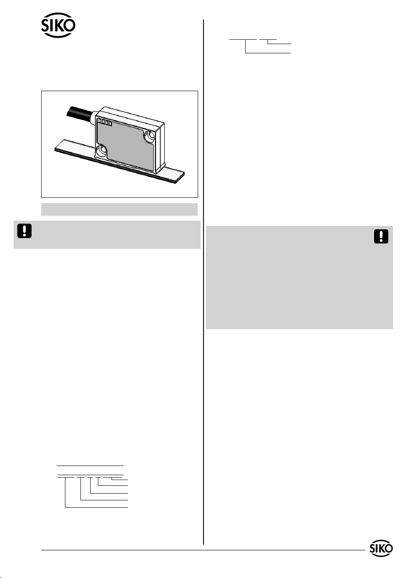
MSK1000
MB100
DEUTSCH
Sensordarstellungen sind exemplarisch und gültig
für alle Bauformen, sofern nicht gesondert be-
schrieben.
1. Gewährleistungshinweise
Lesen Sie vor der Montage und der Inbetriebnahme
dieses Dokument sorgfältig durch. Beachten Sie zu
Ihrer eigenen Sicherheit und der Betriebssicherheit
alle Warnungen und Hinweise.
Ihr Produkt hat unser Werk in geprüftem und be-
triebsbereitem Zustand verlassen. Für den Betrieb
gelten die angegeben Spezifikationen und die
Angaben auf dem Typenschild als Bedingung.
Garantieansprüche gelten nur für Produkte der
Firma SIKO GmbH. Bei dem Einsatz in Verbindung
mit Fremdprodukten besteht für das Gesamtsystem
kein Garantieanspruch.
Reparaturen dürfen nur im Werk vorgenommen
werden. Für weitere Fragen steht Ihnen die Firma
SIKO GmbH gerne zur Verfügung.
2. Identifikation
Magnetband: Das Magnetband ist durch eine fort-
laufende Bedruckung identifizierbar.
•
•
•
•
Bestellbezeichnung zu.
z.B. MSK1000-0023
Varianten-Nr.
Geräte-Typ
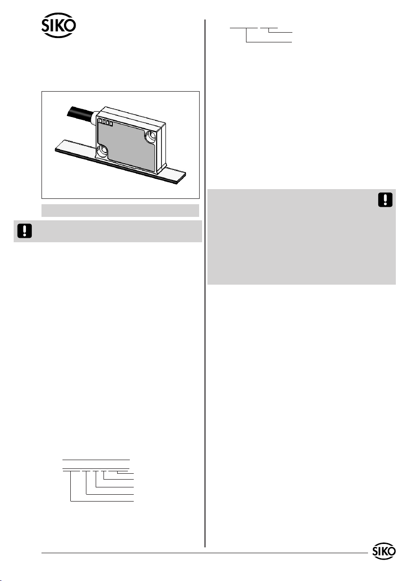
3. Mechanische Montage
Die Montage darf nur gemäß der angegebenen IP-
Schutzart vorgenommen werden. Das System muss
ggfs. zusätzlich gegen schädliche Umwelteinflüs-
se, wie z.B. Spritzwasser, Lösungsmittel, Staub,
Schläge, Vibrationen, starke Temperaturschwan-
kungen geschützt werden.
3.1 Montage Magnetband
Die Montage muss plan zur Montagefläche bzw. der
zu messenden Strecke erfolgen. Welligkeiten ver-
schlechtern immer die Messgenauigkeit.
Aus technischen Gründen muss bei der Länge,
gegenüber der Messstrecke, ein Zumaß von min.
56mm berücksichtigt werden.
Achtung! Um optimale Verklebungen zu errei-
chen müssen alle antiadhäsiven Fremdsubstanzen
(Öl, Fett, Staub usw.) durch möglichst rückstands-
los verdunstende Reinigungsmittel entfernt wer-
den. Als Reinigungsmittel eignen sich u.a. Ketone
(Aceton) oder Alkohole, die u.a. von den Firmen
Loctite und 3M als Schnellreiniger angeboten wer-
den. Die Klebeflächen müssen trocken sein und es
ist mit höchstmöglichem Anpreßdruck zu verkle-
ben. Die Verklebungstemperatur ist optimal zwi-
schen 20°C und 30°C in trockenen Räumen.
Tip! Bei Verklebung langer Bänder sollte die
Schutzfolie des Klebebandes über eine kurze Teil-
strecke abgezogen werden, um das Band zu fixie-
ren. Daraufhin erfolgt das Ausrichten des Bandes.
Nun kann über die restliche Länge die Schutzfolie,
unter gleichzeitigem Andruck des Bandes, seitlich
herausgezogen werden (als Hilfsmittel kann eine
Tapetenandrückwalze verwendet werden).
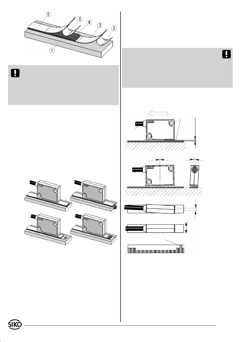
Montageschritte (Abb. 1)
Befestigungsfläche (1) sorgfältig reinigen.
Am Magnetband die Schutzfolie (2) des Klebe-
bandes (3) entfernen.
Magnetband (4) aufkleben.
Magnetbandoberfläche sorgfältig reinigen.
Am Abdeckband (5) die Schutzfolie (6) des Kle-
bebandes entfernen.
Abdeckband aufkleben (an beiden Enden leicht
überlappen lassen).
Die überlappenden Enden des Abdeckbandes gegen
Ablösen sichern.
•
•
•
•
•
•
•
Benutzerinformation
MSK1000 Magnetsensor
MB100 Magnetband
Magnetsensor: Das Typenschild zeigt den Ge-
rätetyp mit Variantennummer. Die Lieferpapiere
ordnen jeder Variantennummer eine detaillierte
Chargennummer
Referenzpunkt
Werkstoff-Trägerband
Genauigkeit
MB Typ
MBxxxx GEK WT RP NNNNNN
2 MSK1000 + MB100 Datum 30.08.2010 Art.Nr. 83389 Änd. Stand 292/10
Abb. 2 Abb. 3
Abb. 4 Abb. 5
Abb. 1: Montage Magnetband
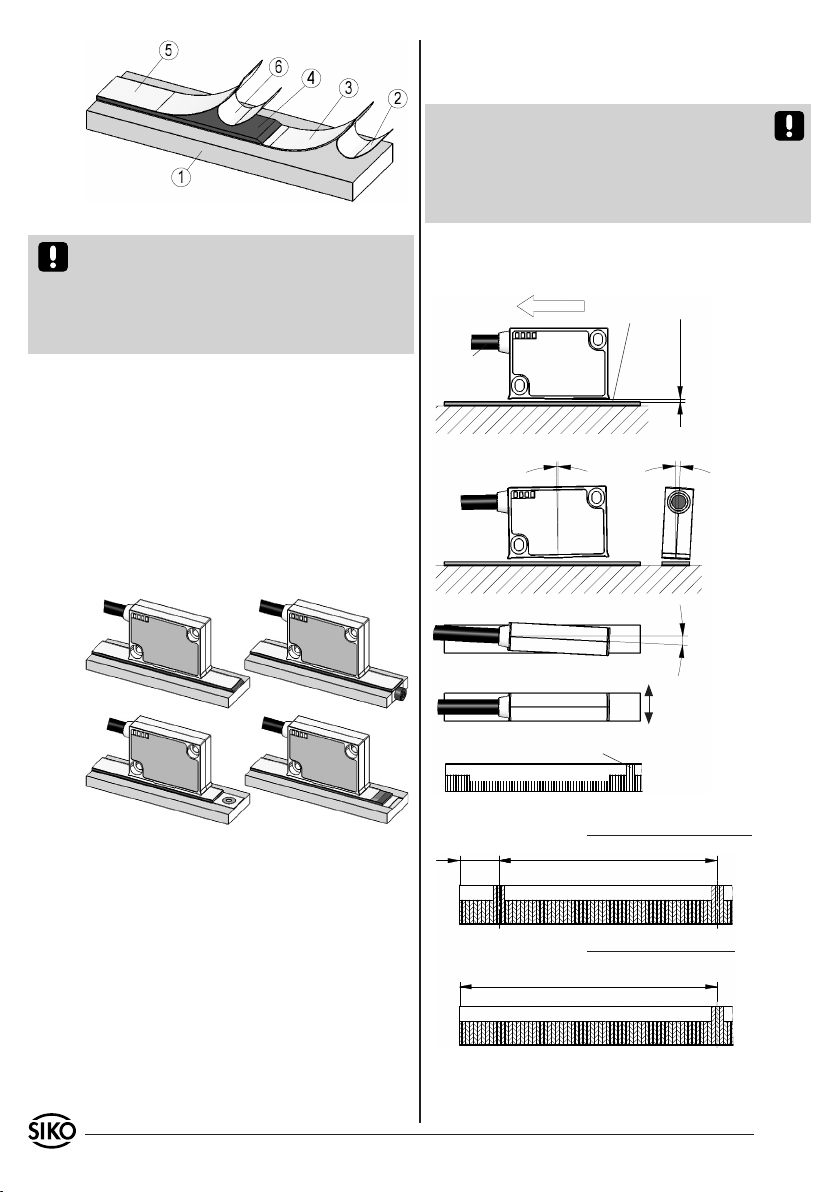
0.1mm ... 0.4mm
ohne Referenzpunkt
0.1mm ... 0.2mm
mit Referenzpunkt
Abstand Sensor/Magnetband
Maximale Fluchtungsfehler
< 1°
< 3°
< 3°
aktive Seite
Verfahrrichtung
Kabelabgangs-
richtung
Signal
A vor B
Referenzpunktlage zur Magnetbandbe-
druckung
Zul. Abweichung
Mitte Band/Sensor:
ohne Ref. ±2mm
mit Ref. ±0.5mm
MBxxxx GEK WT RP NNNNNN
falls sich die Zählrichtung in der elektronischen
Auswertung umkehren läßt (wie z.B. bei den
Magnetbandanzeigen von SIKO).
Abstandslehre vollflächig zwischen Sensor und
Magnetband legen. Hinweis: Betrifft nur Sensoren
ohne Referenzsignal R.
Achtung! Die Toleranz- und Abstandsmaße müs-
sen über die gesamte Messstrecke eingehalten
werden. Der maximale Abstand ohne Abdeckband
beträgt 0,4mm. Bei Verwendung eines Abdeckban-
des reduziert sich der eff. Abstand um die Dicke
des Abdeckbandes inkl. Klebefolie. Der Sensor darf
das Magnetband nicht berühren.
Anwendung LINEAR MSK1000 mit MB100:
•
3.2 Montage Magnetsensor MSK1000
Der Magnetsensor MSK1000 kann durch Verwen-
dung von 2 Schrauben M3 über die Langlöcher
befestigt werden. Es wird empfohlen die beilie-
genden Befestigungsschrauben und Federringe zu
verwenden (Anzugsmoment 1Nm).
Kabel sind so zu verlegen, dass keine Beschä-
digungsgefahr besteht. Zugentlastung und
wenn nötig Schleppkette oder Schutzschlauch
vorsehen.
Auf richtige Ausrichtung bezüglich der Zähl-
richtung achten (Abb. 6). Dies ist unerheblich
•
•
Achtung! Die Beeinflussung durch magnetische
Felder ist zu vermeiden. Insbesondere dürfen keine
Magnetfelder (z.B. Haftmagnete oder andere Dau-
ermagnete) in direkten Kontakt mit dem Magnet-
band geraten. In stromlosem Zustand werden Be-
wegungen oder Verstellungen des Magnetsensors
von der Folgeelektronik nicht erkannt und erfasst.
Montagebeispiele
Die einfache Montageart, durch angeschrägtes
Schutzband (Abb. 2), ist nur in sehr geschützter
Umgebung zu empfehlen. Bei ungeschützer Um-
gebung besteht Abschälgefahr. In solchen Fällen
sind Montagearten, wie in Abb. 3 und 4 gezeigt,
geeigneter.
Den optimalen Schutz bietet die Montage in ei-
ner Nut (Abb. 5), die so tief sein sollte, dass das
Magnetband vollständig darin eingebettet werden
kann.
MSK1000 + MB100 Datum 30.08.2010 Art.Nr. 83389 Änd. Stand 292/10 3
Abb. 6: Definition der Zählrichtung mit Magnetband
und Montage Sensor/Magnetband, Abstandsmaße,
Toleranzen
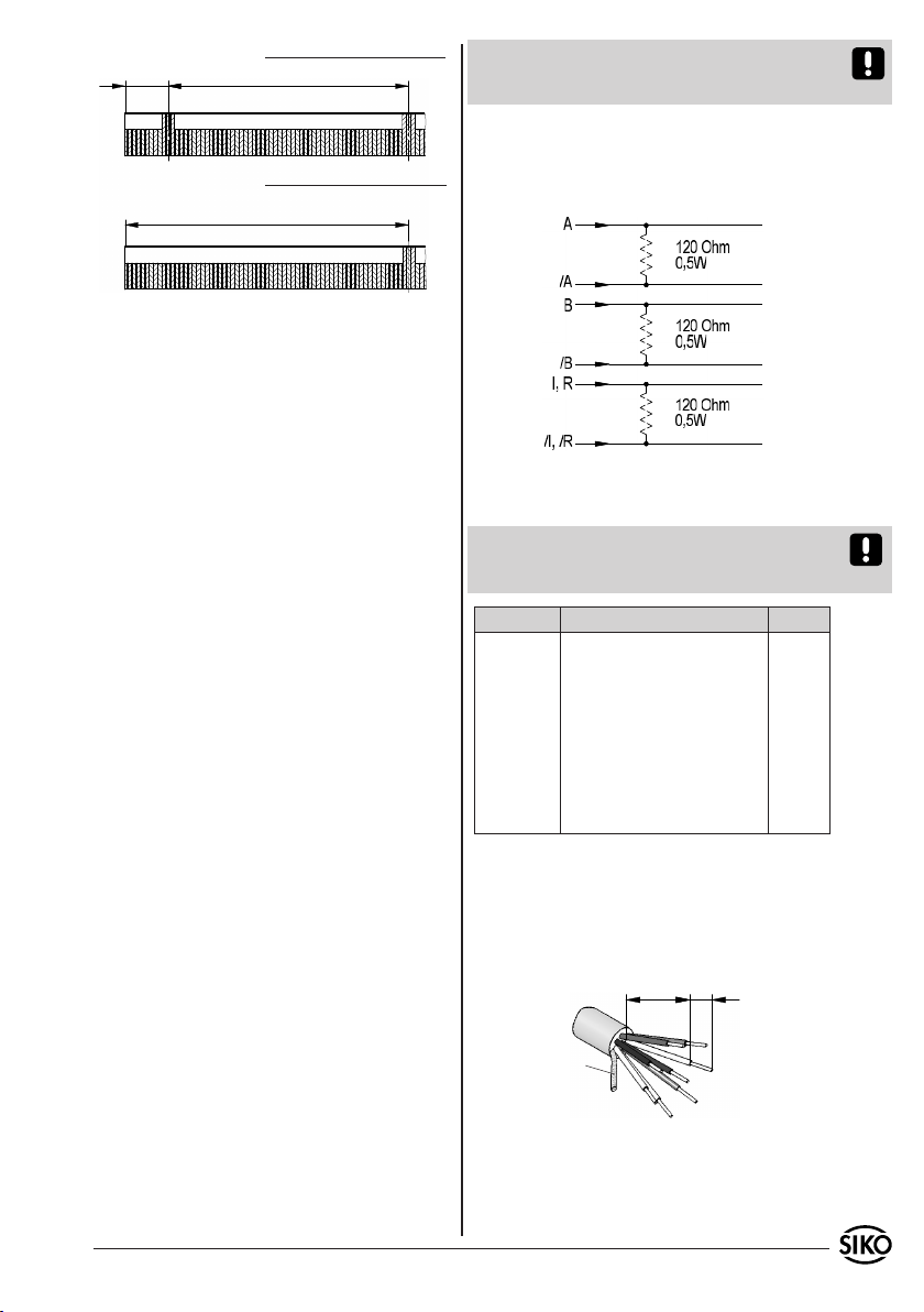
Lage Ref.Punkt R=entspr. Lieferpapiere
Lage Ref.Punkt E=entspr. Lieferpapiere
min. 0,01m
Symbolische Dar-
stellung der Pole Einmaliger Referenzpunkt
Referenzpunkt periodisch
10
so kurz wie
möglich
Schirm
5
Abb. 7: Anschluss E1
Achtung! Die maximale Länge des Anschlusskabels
zwischen Sensor und Nachfolgeelektronik beach-
ten.
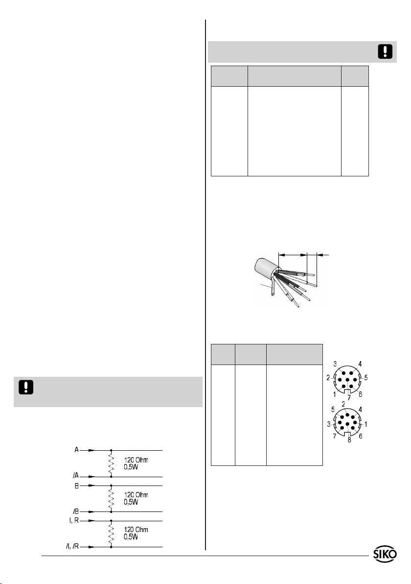
4.1 Anschlusshinweis nach RS422 Norm
Es ist darauf zu achten, dass die Kanäle mit einem
Abschlusswiderstand von 120 Ohm abgeschlossen
werden.
4. Elektrischer Anschluss
Verdrahtungsarbeiten dürfen nur spannungslos
erfolgen!
Vor dem Einschalten sind alle Leitungsanschlüsse
und Steckverbindungen zu überprüfen.
Hinweise zur Störsicherheit
Alle Anschlüsse sind gegen äußere Störeinflüsse
geschützt. Der Einsatzort ist aber so zu wählen,
dass induktive oder kapazitive Störungen nicht
auf den Sensor oder dessen Anschlussleitung
einwirken können! Durch geeignete Kabelführung
und Verdrahtung können Störeinflüsse (z.B.von
Schaltnetzteilen, Motoren, getakteten Reglern
oder Schützen) vermindert werden.
Erforderliche Maßnahmen:
Nur geschirmtes Kabel verwenden. Den Kabel-
schirm beidseitig auflegen. Litzenquerschnitt der
Leitungen min. 0,14mm²; max.0,5mm².
Die Verdrahtung von Abschirmung und Masse (0V)
muss sternförmig und großflächig erfolgen. Der An-
schluss der Abschirmung an den Potentialausgleich
muss großflächig (niederimpedant) erfolgen.
Das System muss in möglichst großem Abstand von
Leitungen eingebaut werden, die mit Störungen
belastet sind; ggfs. sind zusätzliche Maßnahmen
wie Schirmbleche oder metallisierte Gehäuse
vorzusehen. Leitungsführungen parallel zu Ener-
gieleitungen vermeiden.
Schützspulen müssen mit Funkenlöschgliedern
beschaltet sein.
Spannungsversorgung
Die Spannungswerte sind abhängig von der Sen-
sorausführung und sind den Lieferpapieren sowie
dem Typenschild zu entnehmen.
z.B.: 6,5VDC ... 30VDC
•
•
•
•
•
•
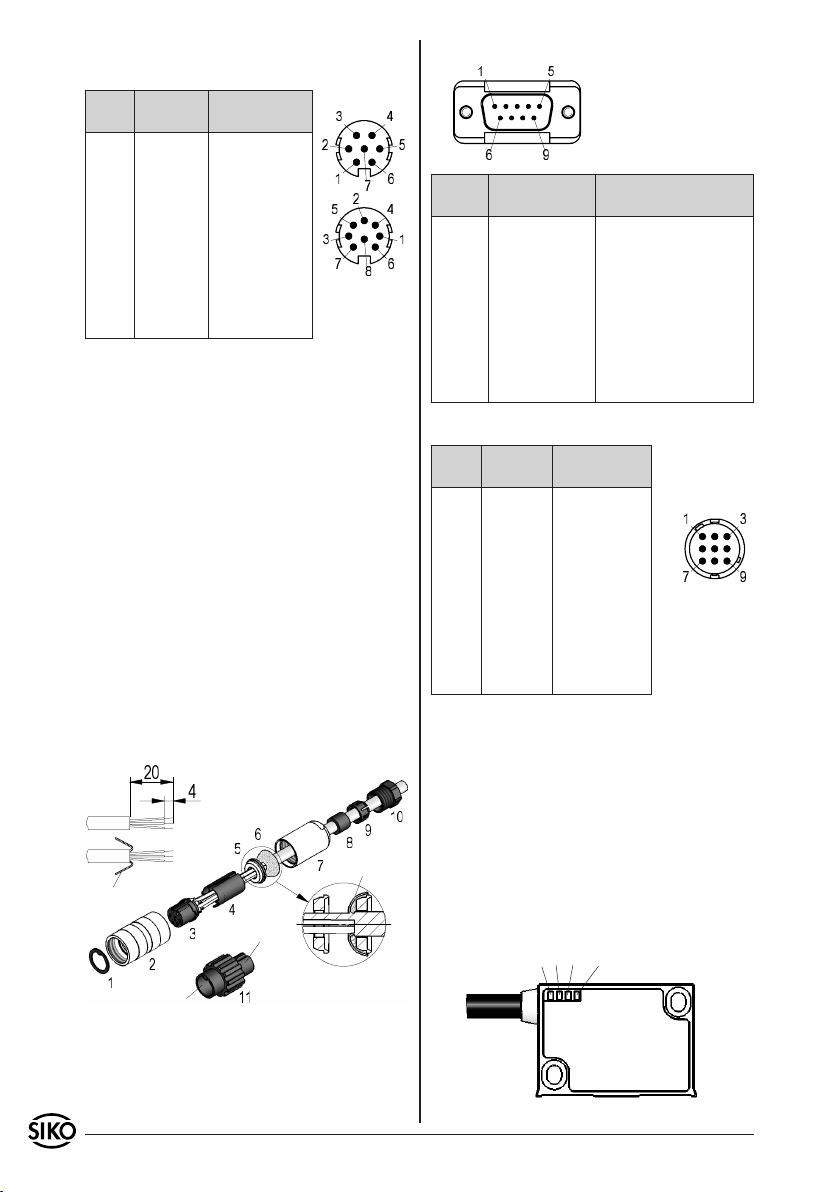
4.2 Anschlussarten
E1: Anschluss mit offenen Kabelenden.
Achtung! Verzinnte Litzen dürfen nicht in Verbin-
dung mit Schraubklemmverbindungen eingesetzt
werden.
invertiert invertiert mit Indexsignal Signal
rot rot A
orange orange B
- - - blau I, R
braun braun +UB
schwarz schwarz GND
gelb gelb /A
grün grün /B
- - - violett /I, /R
Ummantelung entfernen.
Schirm auftrennen und verdrillen.
Litzen ca. 5mm abisolieren und verdrillen.
Aderendhülsen aufquetschen.
1.
2.
3.
4.
4 MSK1000 + MB100 Datum 30.08.2010 Art.Nr. 83389 Änd. Stand 292/10
A B I/R Power
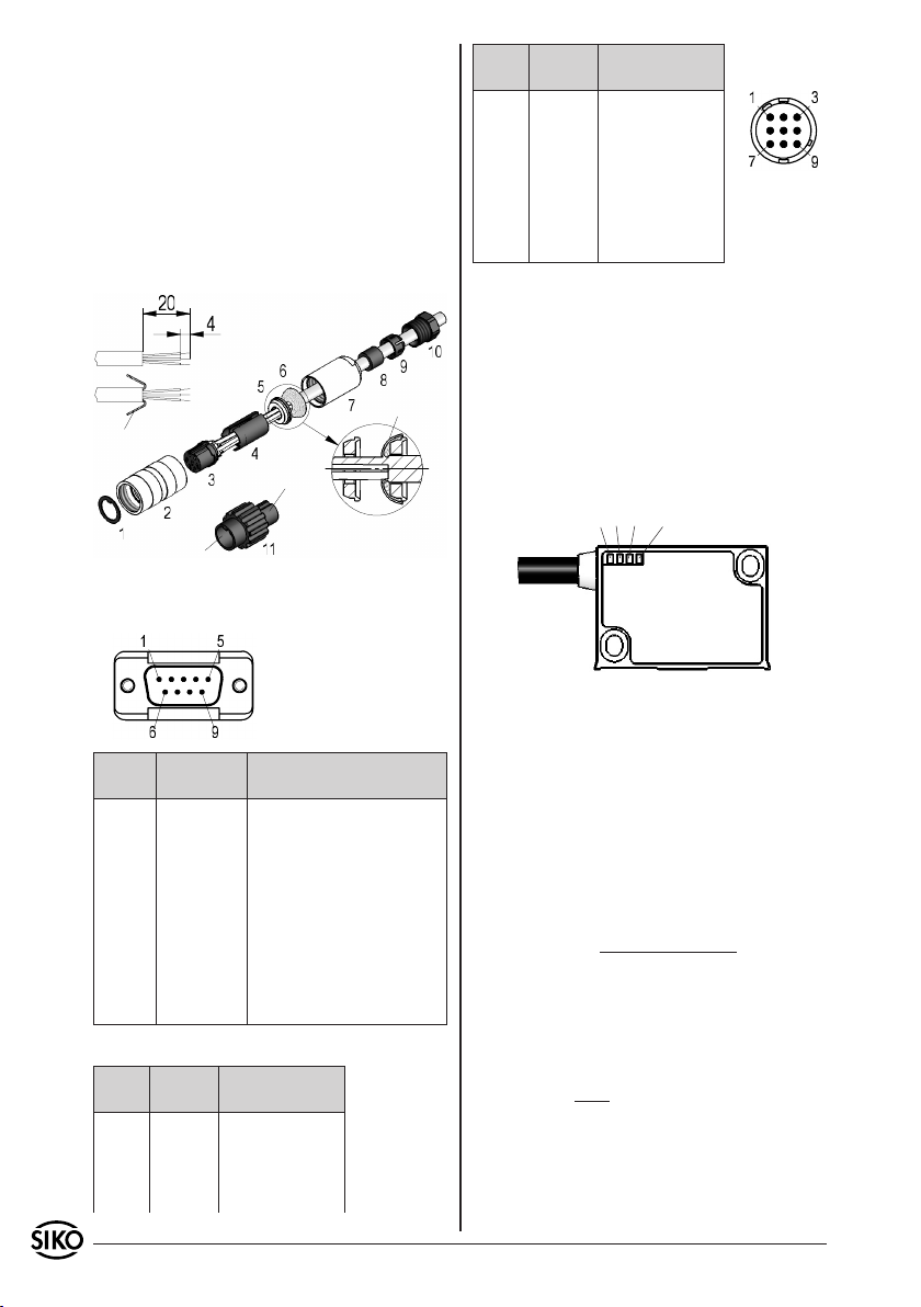
Abb. 8: Montage Anschlussart E6
Schirm
Buchsenteil
Stiftteil
Schirm
Ansichtseite = Steckseite
Stifteinsatz
Ansichtseite =
Steckseite
Stiftkontakt
Ansichtseite
= Steckseite
Stifteinsatz
E6: Anschluss mit Kupplungsstecker und Kupp-
lungsdose. Steckermontage entsprechend Abb. 8.
Signal invertiert invertiert mit
Indexsignal
A Pin 1 Pin 1
B 2 2
I, R - - - 3
+UB 4 4
GND 5 5
/A 6 6
/B 7 7
/I, /R - - - 8
- - - 3
Pos. 6 ... 10 über Kabelmantel schieben.
Kabel abisolieren.
Schirm umlegen.
Pos. 5 auf Litzen schieben.
Litzen an Pos. 3 löten (entspr. Anschluss-
plan).
Abstandhülse Pos. 4 aufweiten und über Litzen
stülpen, zusammendrücken und auf Pos. 3 ste-
cken. Schlitz und Nut (Pos. 3 und 4) müssen
deckungsgleich sein.
Pos. 6 an Pos. 5 drücken, überstehenden Schirm
abschneiden.
Pos. 2 und 7 aufschieben und mittels Montage-
werkzeug Pos. 11 verschrauben.
Pos. 8 in Pos. 9 stecken, beides in Pos. 7
schieben.
Pos. 10 mit Pos. 7 verschrauben.
Pos. 1 in Pos 2. schieben.
1.
2.
3.
4.
5.
6.
7.
8.
9.
10.
11.
E8: Anschluss mit 9-poligem D-SUB Stecker
Signal invertiert invertiert mit Index-
signal
A Pin 1 Pin 1
B 2 2
I, R - - - 3
+UB 4 4
GND 5 5
/A 6 6
/B 7 7
/I, /R - - - 8
- - - 3, 8, 9 9
E14X: Anschluss mit 9-poligem Stecker.
Signal invertiert invertiert mit
Indexsignal
A Pin 1 Pin 1
B 2 2
I, R - - - 3
+UB 8 8
GND 7 7
/A 4 4
/B 5 5
/I, /R - - - 6
- - - 3,6 ---
Schirm 9 9
5. Inbetriebnahme
Nach ordnungsgemäßer Montage und Verdrahtung
kann das Messsystem durch Einschalten der Ver-
sorgungsspannung in Betrieb genommen werden.
Das Gerät initialisiert sich selbstständig nach dem
Einschalten.
Nur Bauform "M": Die "Power"-Leuchtdiode (grün)
im Sensorgehäuse leuchtet. Beim Verfahren des
Magnetsensors über das Magnetband blinken die
Leuchtdioden A, B und I/R (rot) entsprechend
auf.
MSK1000 + MB100 Datum 30.08.2010 Art.Nr. 83389 Änd. Stand 292/10 5
Das Messsystem MSK1000/MB100 ist Bestandteil
eines inkrementalen Messsystem, dass zur abso-
luten Messung an einer definierten Stelle (Refe-
renzpunkt) referenziert werden muss. Dazu muss
das Referenzsignal mit dem Signal eines Referenz-
wertgebers (z.B. Näherungsschalter) verknüpft
werden.
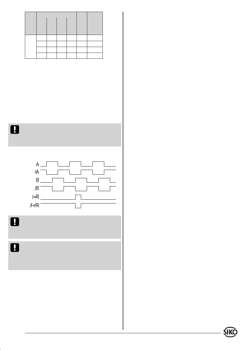
6. Verfahrgeschwindigkeiten (m/s)
Formel zur Berechnung der Verfahrgeschwindig-
keit:
V max. =
(in m/s)
Auflösung in µm
Pulsabstand in µs x 0,8
V = 1
0,25 x 0,8 = 3,2m/s
Auflösung in µm
Pulsabstand
(µs)
Zählfre-
quenz (kHz)
0,2 1 2 5
Verfahrge-
schwindig-
keit in m/s
0,64 3,20 6,40 16,00 0,25 1000,00
0,32 1,60 3,20 8,00 0,50 500,00
0,16 0,80 1,60 4,00 1,00 250,00
0,08 0,40 0,80 2,00 2,00 125,00
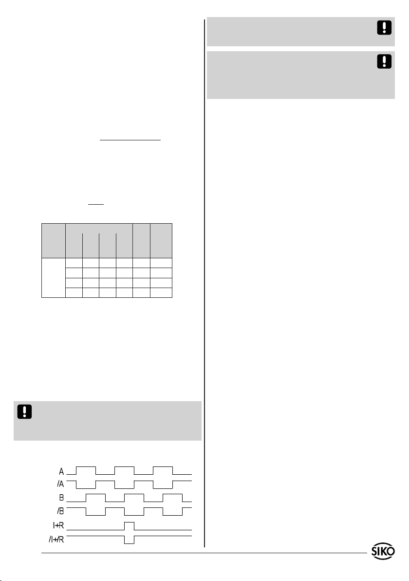
7. Ausgangssignale
Die Auswerteelektronik setzt die magnetischen
Längeninformationen des Magnetsensors in in-
krementale Ausgangssignale um. Die Ausgabe der
Signale erfolgt geschwindigkeitsproportional.
Es ist zu beachten, dass im Stillstand Impulse
von der Breite des eingestellten Pulsabstandes
auftreten können (bedingt durch das interne In-
terpolationsverfahren).
Achtung! Bei der Dimensionierung der Nachfol-
geelektronik ist zu beachten, dass diese für den
eingestellten Pulsabstand bzw. Zählfrequenz aus-
gelegt ist.
Signalfolge
Hinweis: Die Lage des Index- bzw. Referenzsignals
I+R zu den Signalen A und B ist nicht definiert und
kann von der Zeichnung abweichen.
Hinweis: Bei Index-/Referenzsignalbreite von 4
Inkrementen (= 360°), ist der Index/Referenz erst
nach dem 5. Zählschritt (Inkrement) auswertbar.
Nach dem Einschalten der Betriebsspannung ent-
sprechende Verzögerung berücksichtigen.
8. Wartung
Die Oberfläche des Magnetbandes ist bei starker
Verschmutzung durch Staub, Späne, Feuchtigkeit
usw., von Zeit zu Zeit mit einem weichen Lappen
zu reinigen.
9. Fehlerbehandlung
Typische Fehler, die bei Anbau und Betrieb auf-
treten:
Das Magnetband wurde falsch montiert / aktive
Seite nach unten (Kapitel 3.1).
Zum Schutz des Magnetbandes wurde nicht das
mitgelieferte Abdeckband verwendet. Das Abdeck-
band muss nicht magnetisierbar sein.
Der Sensor ist nicht, oder nicht korrekt ange-
schlossen (Pinbelegung Kapitel 4.2).
Die Abstandstoleranz zwischen Sensor und Ma-
gnetband/Magnetring wurde nicht eingehalten
(beim Band über die gesamte Messstrecke!), der
Sensor streift auf dem Magnetring (Abb. 6).
Kabelunterbrechung / Abtrennung durch scharfe
Kanten / Quetschung.
Der Sensor ist mit der aktiven Seite vom Band
abgewandt montiert (Abb. 6).
Der Sensor wurde nicht entsprechend Abb. 6
ausgerichtet.
•
•
•
•
•
•
•
Beispiel:
Auflösung: 1µm
Pulsabstand: 0,25µs

6 MSK1000 + MB100 Datum 30.08.2010 Art.Nr. 83389 Änd. Stand 292/10
MSK1000 + MB100 Datum 30.08.2010 Art.Nr. 83389 Änd. Stand 292/10 7
MSK1000
MB100
ENGLISH
Exemplary sensor illustrations are valid for all sen-
sor types unless described separately.
1. Warranty information
In order to carry out installation correctly, we
strongly recommend this document is read very
carefully. This will ensure your own safety and
the operating reliability of the device.
Your device has been quality controlled, tested
and is ready for use. Please observe all warnings
and information which are marked either directly
on the device or specified in this document.
Warranty can only be claimed for components
supplied by SIKO GmbH. If the system is used
together with other products, there is no warranty
for the complete system.
Repairs should be carried out only at our works.
If any information is missing or unclear, please
contact the SIKO sales staff.
2. Identification
Magnetic strip: identification by printing on the
strip.
•
•
•
•
e.g. MSK1000-0023
version number
type of unit
3. Installation
For mounting, the degree of protection specified
must be observed. If necessary, protect the unit
against environmental influences such as sprayed
water, dust, knocks, extreme temperatures.
3.1 Mounting the magnetic strip
The mounting surface / measuring track must be
flat. Buckles or bumps will lead to measuring in-
accuracies.
For technical reasons the strip should be min.
56mm longer than the actual measuring distance.
Attention! To guarantee optimal adhesion oil,
grease dust etc. must be removed by using clean-
sing agents which evaporate without leaving re-
sidues. Suitable cleansing agents are eg. ketones
(acetone) or alcohols; Messrs. Loctite and 3M can
both supply such cleansing liquid. Make sure that
the surface to be glued is dry and apply the strip
with maximum pressure. Glueing should preferably
be undertaken at temperatures between 20°C to
30°C and in dry atmosphere.
Advice! Wh en applying long pieces of magnetic
strip do not immediately remove the complete pro-
tective foil, but rather peel back a short part from
the end sufficient to fix the strip. Now align the
strip. As the protective strip is then peeled back
and out press the tape firmly onto the mounting
surface. A wall paper roller wheel could be used to
assist in applying pressure onto the magnetic strip
when fixing it in position.
Mounting steps (see fig. 1)
Clean mounting surface (1) carefully.
Remove protective foil (2) from the adhesive
side of the magnetic strip (3).
Stick down the magnetic strip (4).
Clean surface of magnetic strip carefully.
Remove protective foil (6) from adhesive tape on
the cover strip (5).
Fix cover strip (both ends should slightly over-
lap).
Also fix cover strip's ends to avoid unintenti-
onal peeling.
•
•
•
•
•
•
•
User Information
MSK1000 Magnetic sensor
MB100 Magnetic strip
Magnetic sensor: Please check the particular type
of unit and type number from the identification
plate. Type number and the corresponding version
are indicated in the delivery documentation.
batch number
reference point
carrier strip
accuracy
MB type
MBxxxx GEK WT RP NNNNNN
8 MSK1000 + MB100 Datum 30.08.2010 Art.Nr. 83389 Änd. Stand 292/10
Fig. 2 Fig. 3
Fig. 4 Fig. 5
Fig. 1: Mounting of the magnetic strip
Fig. 6: Definition of the counting direction with
magnetic strip and assemblage sensor/magnetic ring,
gap measure, tolerances
Position of the reference point R = as
stated in the delivery documentation
Position of the reference point E = as stated
in the delivery documentation; min. 0,01m
Magnetic poles -
schema Unique reference point
Periodical reference point
10
0.1mm ... 0.4mm wit-
hout reference point
0.1mm ... 0.2mm with
reference point
Gap sensor/magnetic strip
Maximum alignment error
< 1°
< 3°
< 3°
active side
Travel direction
Direction
of outgoing
cable
Signal
A before B
Position of the reference point relating
to the marking on the magnetic strip.
Admissable deviatoion
middle of tape/sensor:
without ref. point ±2mm
with ref. point ±0.5mm
MBxxxx GEK WT RP NNNNNN
Attention! Do not expose the system to magne-
tic fields. Any direct contact of the magnetic strip
with magnetic fields (eg. adhesive magnets or
other permanent magnets) is to be avoided. Sen-
sor movements during power loss are not captured
by the follower electronics.
Mounting examples
Mounting with chamfered ends (fig. 2) is not re-
commended unless the strip is installed in a safe
and protected place without environmental influ-
ences. In less protected mounting places the strip
may peel. There we recommend mounting accord.
to fig. 3 and 4.
Mounting in a groove (fig. 5) best protects the
magnetic strip. The groove should be deep enough
to totally embed the magnetic strip.
Place distance gauge with its complete surface
between sensor and magnetic tape. Note: only
relevant for sensors without reference signal R.
Attention! The tolerance and gap measures must
be observed over the whole measuring length.
The max. gap without cover strip is 0,4mm. When
using cover strip, the gap is reduced by the thick-
ness of cover strip including its adhesive tape.
Sensor must not touch the magnetic strip.
LINEAR application MSK1000 with MB100:
•
3.2 Mounting of the magnetic sensor MSK1000
The magnetic sensor MSK1000 can be fastened by
using two bolts M3 over the elongated holes. We
recommend to use the enclosed fixing screws and
washer springs (fastening torque 1Nm).
Cables should be layed in such a way that there
is no danger of damaging. Provide ten-sion relief
and drag chain or casing, if necessary.
Observe the correct alignment with regard to
the counting direction (fig. 6). This does not
apply if the counting direction can be reversed
in the electronic interpretation (e.g. in SIKO's
magnetic-strip displays).
•
•
MSK1000 + MB100 Datum 30.08.2010 Art.Nr. 83389 Änd. Stand 292/10 9
as short as
possible
screening
5
Fig. 7: Connection type E1
viewing side =
plug-in side
male contact
4.2 Connection type
E1: Flying leads.
Attention! Tinned strands must not used in com-
bination with screw/clamp connections.
inverted inverted with reference
signal
Signal
red red A
orange orange B
- - - blue I, R
brown brown +UB
black black GND
yellow yellow /A
green green /B
- - - violet /I, /R
Remove cable coating.
Open screening and twist it.
Strip stranded wires to a length of 5mm and
twist them.
Pinch stranded wires.
1.
2.
3.
4.
4. Electrical connection
Wiring must only be carried out with power off!
Check all lines and connections before switching
on the equipment!
Interference and distortion
All connections are protected against the effects
of interference. The location should be selected
to ensure that no capacitive or inductive in-
terferences can affect the sensor or the con-
nection lines! Suitable wiring layout and choice
of cable can minimise the effects of interference
(eg. interference caused by SMPS, motors, cyclic
controls and contactors).
Necessary measures:
Only screened cable should be used. Wire cross sec-
tion is to be at least 0,14mm², max. 0,5mm².
Wiring to the screen and ground (0V) must
be secured to a good point. Ensure that the
connection of the screen and earth is made to
a large surface area with a sound connection to
minimise impedance.
The system should be positioned well away from
cables with interference; if necessary a protective
screen or metal housing must be provided. The
running of wiring parallel to the mains supply
should be avoided.
Contactor coils must be linked with spark sup-
pression.
Supply voltage
The voltages depend on the sensor designs; they
are to be taken from the delivery documentation
and the identification plate.
e.g.: 6,5VDC ... 30VDC
Attention! When connecting sensor and follower
electronics, please do not exceed the max. admis-
sable cable length.
4.1 Connection note acc. to RS422 standard
Please provide the channels with a 120 Ohm ter-
minating resistor.
•
•
•
•
•
•
E6: Connection with mit coupler plug and coupler
socket. Plug mounting according to fig. 8.
Signal inverted inverted with
reference signal
A Pin 1 Pin 1
B 2 2
I, R - - - 3
+UB 4 4
GND 5 5
/A 6 6
/B 7 7
/I, /R - - - 8
- - - 3
Slip parts 6 to 10 over outer cable.
Strip cable.
Turn down screening.
Push part 5 onto ferrules.
Solder wires to part 3 (according connection
diagram).
Open spacer (part 4) and put it over ferrules,
1.
2.
3.
4.
5.
6.
10 MSK1000 + MB100 Datum 30.08.2010 Art.Nr. 83389 Änd. Stand 292/10
A B I/R Power
Fig. 8: Coupler socket E6
screening
socket
pin
screening
viewing side = plug-in side
male contact
viewing side=
plug-in side
plug pin
squeeze and push it onto part 3. Slot and keyway
of parts 3 and 4 must align.
Press parts 6 and 5 together; cut prodruding
screening.
Push parts 2 and 7 together and screw part 11
using appropriate tool.
Push part 8 into part 9 and slide both parts
into part 7.
Screw parts 10 and 7 together.
Push part 1 into part 2.
7.
8.
9.
10.
11.
Signal inverted inverted with
reference signal
GND 7 7
/A 4 4
/B 5 5
/I, /R - - - 6
- - - 3,6 ---
shiel-
ding
9 9
5. Commissioning
Following proper installation and wiring, the
measuring system can be commissioned by
switching on the supply voltage. After switching
on, the device initializes itself independently.
Only design "M": The "power" LED (green) in the
sensor housing lights up. While the magnetic sen-
sor travels over the magnetic strip, the LEDs A, B,
and I/R (red) are lighting accordingly.
E8: Connection with 9-pole D-SUB plug
V max. =
(in m/s)
Resolution in µm
Pulse interval in µs x 0,8
V = 1
0,25 x 0,8 = 3,2m/s
The measuring system MSK1000/MB100 is a com-
ponent of an incremental measuring system which
must be referenced at a defined position (refe-
rence point) for absolute measurement. For this
purpose, the reference signal must be linked to
the signal of a reference value encoder (e.g., pro-
ximity switch).
6. Travel speeds (m/s)
Formula for calculating the travel speed:
Example:
Resolution: 1µm
Pulse interval: 0,25µs
Signal inverted inverted with reference
signal
A Pin 1 Pin 1
B 2 2
I, R - - - 3
+UB 4 4
GND 5 5
/A 6 6
/B 7 7
/I, /R - - - 8
- - - 3, 8, 9 9
E14X: Connection with 9-pole plug
Signal inverted inverted with
reference signal
A Pin 1 Pin 1
B 2 2
I, R - - - 3
+UB 8 8
MSK1000 + MB100 Datum 30.08.2010 Art.Nr. 83389 Änd. Stand 292/10 11
Resolution in µm
Pulse interval
(µs)
Counting
frequency
(kHz)
0,2 1 2 5
Travel speed
m/s
0,64 3,20 6,40 16,00 0,25 1000,00
0,32 1,60 3,20 8,00 0,50 500,00
0,16 0,80 1,60 4,00 1,00 250,00
0,08 0,40 0,80 2,00 2,00 125,00
7. Output signals
The translation module translates the length
information of the magnetic sensor into incre-
mental output signals with real-time processing of
the output signals.
Please note that pulses having the width of
the pulse interval set can occur at standstill of
the device (caused by the internal interpolation
method).
Caution! When dimensioning the follow-on elec-
tronics please take care that it is adjusted to the
set pulse interval or counting frequency, respec-
tively.
Signal sequence
Note: The position of the index or reference sig-
nal I+R, respectively, with respect to signals A
and B is not defined and can deviate from the
drawing.
Note: With a 4-increment wide (= 360°) index/
reference signal, index/reference signal interpre-
tation can be made after the 5th counting step
(increment) only. Corresponding time delay has to
be considered when power is switched on.
8. Maintenance
We recommend cleaning the magnetic strip’s sur-
face from time to time with a soft rag. This avo-
ids dirt (dust, chips, humidity ...) sticking to the
strip.
9. Trouble shooting
Below are some typical errors which may occur du-
ring installation and operation:
Magnetic strip incorrectly mounted (active sur-
face must be mounted towards the sensor) (see
chapter 3.1).
Use of foreign protective strip. Must always be
non-magnetic.
Sensor not or incorrectly connected (pin connec-
tion, see chapter 4.2).
Tolerance for the gap between magnetic sensor and
magnetic strip not observed over the total travel
distance. Sensor touches strip (see fig. 6).
Cable squeezed / interrupted / cut by sharp
edges.
Sensor's active side not mounted towards the
magnetic strip (see fig. 6).
Sensor has not been aligned according to fig.
6.
•
•
•
•
•
•
•

12 MSK1000 + MB100 Datum 30.08.2010 Art.Nr. 83389 Änd. Stand 292/10
SIKO GmbH
Werk / Factory:
Weihermattenweg 2
79256 Buchenbach-Unteribental
Postanschrift / Postal address:
Postfach 1106
79195 Kirchzarten
Telefon/Phone +49 7661 394-0
Telefax/Fax +49 7661 394-388
E-Mail info@siko.de
Internet www.siko.de
Service [email protected]e
Other manuals for MSK1000
1
This manual suits for next models
1
Table of contents
Languages:
Other Siko Accessories manuals


Popular Accessories manuals by other brands

Nexmosphere
Nexmosphere XE Series product manual

Honeywell
Honeywell NOTIFIER SMART 2 NFX-SMT2 Installation and maintenance instructions

Philips
Philips SPF1902 Specifications

Knick
Knick SE715 Series Instructions for use

REV Ritter
REV Ritter 468344 operating instructions

Philips
Philips 21193-8 specification


