Siko MSA213C User manual


MSA213C-S (BiSS/C)
Deutsch
MSA213C-S (BiSS/C) · Datum 24.05.2022 · Art. Nr. 90036 · Änd. Stand 111/22
2
Inhaltsverzeichnis
1 Dokumentation . . . . . . . . . . . . . . . . . . . . 3
1.1 Historie . . . . . . . . . . . . . . . . . . . . . . 3
2 Sicherheitshinweise . . . . . . . . . . . . . . . . . . 3
3 Inbetriebnahme . . . . . . . . . . . . . . . . . . . . 3
3.1 Kalibrierung des Messsystems . . . . . . . . . . . . . 3
4 Messbereich . . . . . . . . . . . . . . . . . . . . . . 3
5 BiSS C (bidirektional) - Schnittstelle . . . . . . . . . . . 4
6 Schnittstellen . . . . . . . . . . . . . . . . . . . . . 7
6.1 Analogschnittstelle . . . . . . . . . . . . . . . . . 7
6.2 Digitalschnittstelle . . . . . . . . . . . . . . . . . 8
7 Servicemode (RS485-Mode) . . . . . . . . . . . . . . . 9
7.1 Applikation MSA213C mit Servicemode . . . . . . . . 10
7.2 Befehlsliste . . . . . . . . . . . . . . . . . . . 10

MSA213C-S (BiSS/C)
Dokumentation Deutsch
MSA213C-S (BiSS/C) · Datum 24.05.2022 · Art. Nr. 90036 · Änd. Stand 111/22
3
1 Dokumentation
Es gelten weitere Dokumente, siehe Auflistung in der Originalmontagean-
leitung.
Diese Dokumente sind auch unter "http://www.siko-global.com/p/
msa213c" zu finden.
1.1 Historie
Änderung Datum Beschreibung
340/18 19.04.2021 Dokument erstellt
111/22 23.05.2022 Text in Kap. 7 geändert
Bezeichnungen in Abb. 3 geändert
2 Sicherheitshinweise
Es gelten die Sicherheitshinweise der Originalmontageanleitung.
3 Inbetriebnahme
Nach Ordnungsgemäßer Montage und Verdrahtung des Messsystems,
bestehend aus Sensor MSA213C und Magnetband MBA213, kann dieses
durch Anlegen der Betriebsspannung (siehe Montageanleitung MSA213C)
in Betrieb genommen werden.
3.1 Kalibrierung des Messsystems
Ab Werk ist der Kalibrierwert auf 0 voreingestellt. Der Sensor gibt den
Absolutwert des Magnetbandes als Positionswert aus (0 … 16383999µm).
Da das Magnetband Rollenware ist, muss im Sensor ein Nullpunkt an der
gewünschten Position gesetzt werden (nur dann zählt der Sensor korrekt
über die gesamte Messlänge).
Bei dem MSA213C handelt es sich um ein absolutes Messsystem, d. h. die
Information des Positionswertes ist als Absolutwert im Maßstab (Magnet-
band MBA213) verkörpert. Über verschiedene Befehle kann im Service-
Modus der Messbereich angepasst werden (siehe Kapitel 4und Kapitel 7).
4 Messbereich
Im Folgenden werden die Befehle zur Festlegung des Messbereichs anhand
von Beispielen dargestellt.
ACHTUNG
MSA213C-S (BiSS/C)
BiSS C (bidirektional) - Schnittstelle Deutsch
MSA213C-S (BiSS/C) · Datum 24.05.2022 · Art. Nr. 90036 · Änd. Stand 111/22
4
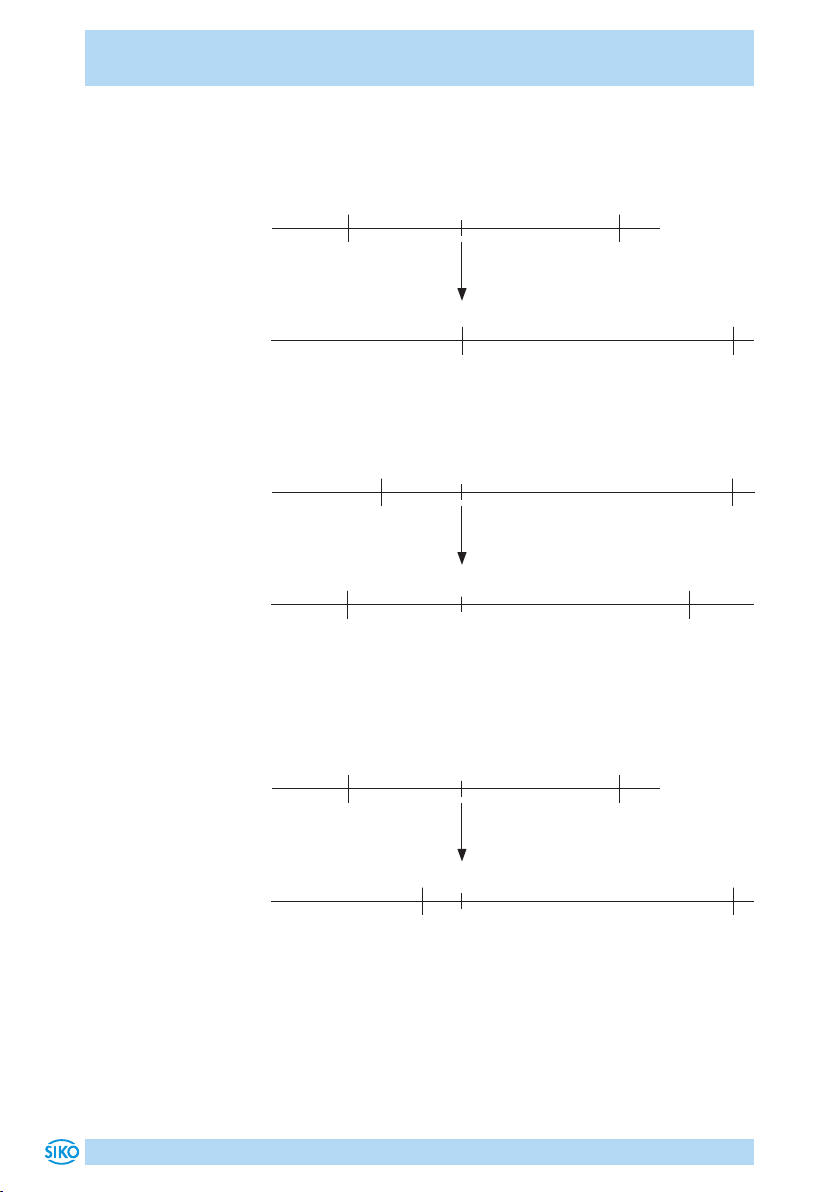
Nullpunkt setzen
Die aktuelle Position wird als Nullpunktwert festgelegt.
0 0
16383999 4000000 16383999
0 0
16383999 16383999
BiSS C Befehl (Kapitel 5)
RS485 Befehl Sxxxxx
-> SCZP (ASCI)
-> S00000
Bandkodierung
Positionswert
Sensor
Kalibrierwert schreiben (Absolut Oset) (ab SW V4.0)
Die aktuelle Position wird um den Oset-Wert erhöht.
0 0
16383999 4000000 16383999
0 0
16383999 16383999
RS485 Befehl Fxyyyyyyyyyyyy -> F1000001000000 schreibt Oset-Wert 1m
Bandkodierung
Positionswert
Sensor 5000000
Nullpunktwert + Kalibrierwert schreiben (Absolut Oset) (ab SW V4.0)
Die aktuelle Position wird als Nullpunktwert festgelegt und anschließend
um den Oset-Wert erhöht.
0 0
16383999 4000000 16383999
0 0
16383999 16383999
RS485 Befehl Gxxxxxxxxxx -> G0001000000 setzt Nullpunkt und
Oset-Wert 1m
Bandkodierung
Positionswert
Sensor 1000000
5 BiSS C (bidirektional) - Schnittstelle
Der Sensor verfügt über eine BiSS C (bidirektional) Schnittstelle und kann
über diese auch parametrisiert werden. Dafür können einzelne Register
beschrieben oder auch Commands abgesetzt werden.
MSA213C-S (BiSS/C)
BiSS C (bidirektional) - Schnittstelle Deutsch
MSA213C-S (BiSS/C) · Datum 24.05.2022 · Art. Nr. 90036 · Änd. Stand 111/22
5
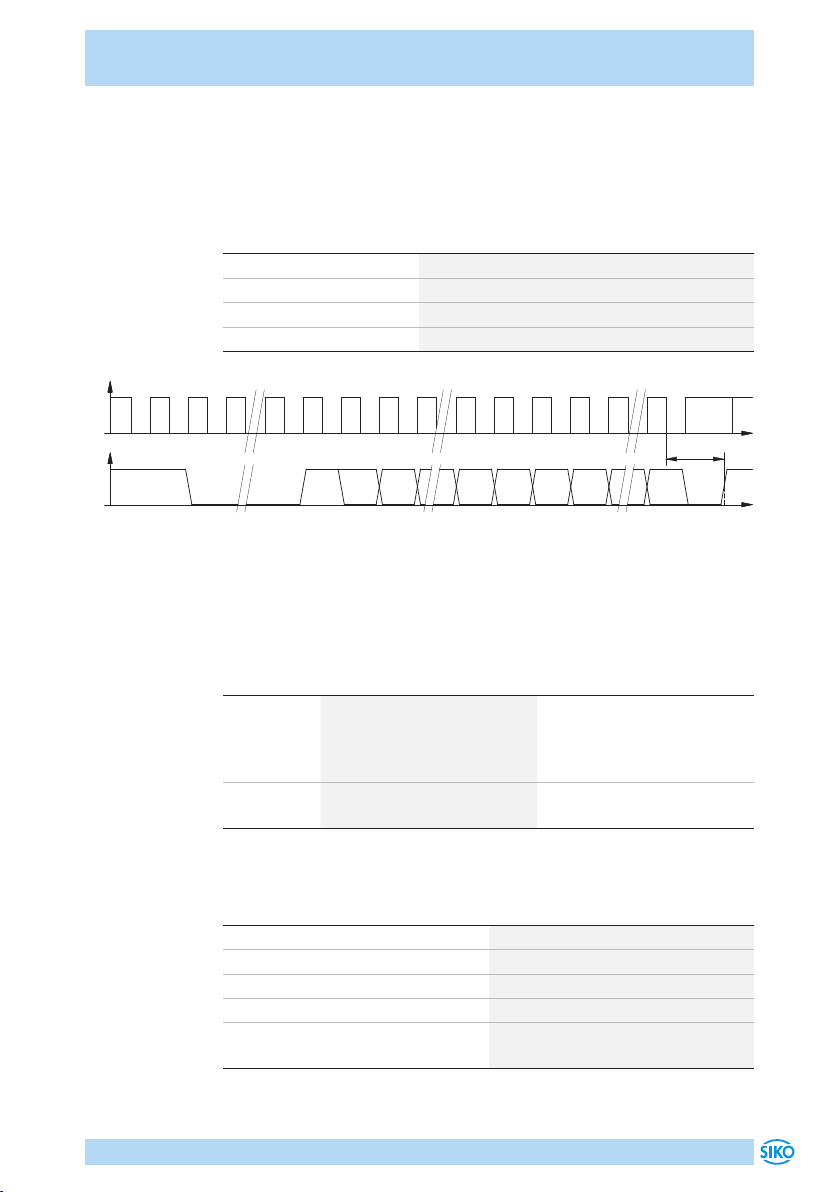
Datenformat
Der Sensor verwendet den BP3 Standard mit 25 Bit Position, 1 Bit Plau-
sibilitäts-Error, 1 Bit Sensor/Band Abstands-Warnung und 6 Bit CRC. Die
Daten werden in einem 33 Bit-Format rechtsbündig ausgegeben.
Merkmal Technische Daten
Position Bit Länge 25 Bit (1 Bit Vorzeichen, 24 Bit Wert)
Error Bit Länge 1 Bit, Position Plausibilitätsfehler
Warning Bit Länge 1 Bit, Sensor Band Abstandswarnung
CRC Länge 6 Bit (CRC Polynominal 0x43)
MA
SLO
CDM
t
tm
t
Start CDS
ACK ... Busy ... MSB E
LSB WCRC
MSB
CRC
LSB
Bedeutung der Fehler Bits
Zusätzlich zu den 25 Bit Positionsdaten werden mit zwei weiteren Bits Feh-
lerzustände signalisiert. Die Bits werden bei Einhaltung der Grenzwerte
automatisch zurückgesetzt.
Bit = 0 Bit = 1
Fehler Bit 1
(Bit 26)
Plausibilitätsfehler. Der über
die BiSS C-Schnittstelle aus-
gegebene Positionswert ist
ungültig.
kein Plausibilitätsfehler
Fehler Bit 2
(Bit 27)
Sensor/Band Abstandswar-
nung
Der Sensor ist korrekt über
dem Magnetband.
Timing
Merkmal Technische Daten
Aufstartzeit <250ms
Sensor Messzykluszeit 40µs
Maximale Clock Frequenz 10MHz, abhängig von Kabellänge
BiSS C Timeout Adaptiv
Maximale BiSS C Frame Wiederhol-
rate
50µs (bei 10MHz Clock Cycle Time)
Other manuals for MSA213C
1
Table of contents
Languages:
Other Siko Accessories manuals


