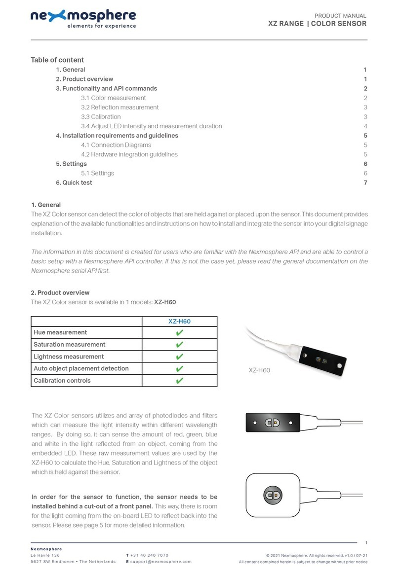
Nexmosphere XE Series User manual

1. General
The XE Ambient Light sensor measures the intensity of the light in the environment in which it is placed, facilitating
applications such as the adjustment of display brightness levels based on environmental light conditions. This document
provides explanation of the available functionalities and instructions on how to install and integrate the sensor into your
digital signage installation.
The information in this document is created for users who are familiar with the Nexmosphere API and are able to control a
basic setup with a Nexmosphere API controller. If this is not the case yet, please read the general documentation on the
Nexmosphere serial API rst.
2. Product overview
Nexmosphere
Le Havre 136
5627 SW Eindhoven • The Netherlands
T+31 40 240 7070
Esupport@nexmosphere.com
PRODUCT MANUAL
XE RANGE | AMBIENT LIGHT SENSOR
© 2023 Nexmosphere. All rights reserved. v1.0 / 03-23
All content contained herein is subject to change without prior notice
1
Table of content
1. General 1
2. Product overview 1
3. Functionalities and API commands 2
3.1 Ambient light measurement 2
4. Installation requirements and guidelines 3
4.1 Connection Diagrams 3
4.2 Hardware integration guidelines 3
5. Settings 4
6. Quick test 5
XE-A20
Ambient light measurement
✔
The XE Ambient Light sensor measures the intensity of ambient light and can be adhered to any object or surface. The
device consists of one small sensor that is hidden beneath a translucent diusing cover that measures the intensity of the
incoming light (in Lux).
XE-A20

© 2023 Nexmosphere. All rights reserved. v1.0 / 03-23
All content contained herein is subject to change without prior notice
Nexmosphere
Le Havre 136
5627 SW Eindhoven • The Netherlands
T+31 40 240 7070
Esupport@nexmosphere.com
2
PRODUCT MANUAL | XE AMBIENT LIGHT SENSOR
3.1 Ambient light measurement
When the sensor is connected, it will immediately start measuring the current ambient light intensity. Per default, the sensor
will send out an API command when the measured light intensity enters a new range, varying from 1 to 9. This API message
has the following format:
*Light intensity range in 1- 9
X001B[Ar=*]
Range Light intensity
1 0 - 1 lux
2 1 - 50 lux
3 50 - 250 lux
4 250 - 1.000 lux
5 1.000 - 5.000 lux
6 5.000 - 15.000 lux
7 15.000 - 40.000 lux
8 40.000 - 80.000 lux
9 80.000 - 120.000 lux
The default light intensity values per range are as follows.
In addition to the default range triggers, the XE Ambient Light sensor can also be set to provide the absolute light intensity
value (in lux) as output. In order to do so, the output mode must be adjusted by sending the following setting command.
Set output mode to Lux
X001S[4:2]
The API command for light intensity value output will have
the following format:
X001B[Av=XXXXXX]XXXXXX = 0 - 120.000 lux
Data requests
The light intensity values can also be requested at any time by sending one of the following API commands:
Request current light intensity (lux) value
X001B[LUX?]
The reply will be identical to the triggered light intensity value API message such as listed above.
3. Functionalities and API commands
The XE Ambient Light sensor provides the following functionality:
1. Ambient light measurement - measures the ambient light intensity and triggers in ranges or
Lux
The following sections will cover each of these functionalities in detail. Please note that for each API example in this
document, X-talk interface address 001 is used (X001). When the sensor is connected to another X-talk channel,
replace the "001" with the applicable X-talk address.
Example API messages
Example API messages
Light intensity measured of 6.000 lux
Light intensity measured of 550 lux
Light intensity measured of 55.000 lux
Light intensity measured of 98.000 lux
X001B[Ar=6]
X001B[Av=000550]
X001B[Ar=8]
X001B[Av=098000]
There are four dierent range mappings available that
can be used to adjust the light intensity values of the
ranges. More information can be found on page 4 of this
document, setting 7.

© 2023 Nexmosphere. All rights reserved. v1.0 / 03-23
All content contained herein is subject to change without prior notice
Nexmosphere
Le Havre 136
5627 SW Eindhoven • The Netherlands
T+31 40 240 7070
Esupport@nexmosphere.com
3
PRODUCT MANUAL | XE AMBIENT LIGHT SENSOR
4. Installation requirements and guidelines
When integrating an XE Ambient Light sensor into your digital signage installation, several installation requirements and
guidelines need to be taken into account in order for the sensor to perform optimal and operate stable.
4.1 Connection Diagrams
The XE Ambient Light sensor can be connected to any X-talk interface and is therefore compatible with all Xperience
controllers. Make sure the XE Ambient Light sensor is connected to the X-talk interface before powering the Xperience
controller. Otherwise, the sensor will not be recognized by the Xperience controller and no output will be provided.
Example connection to XC Controller Example connection to XN Controller
4.2 Hardware integration guidelines
Installation with double sided tape
The XE Ambient Light sensor is typically installed using
the double-sided tape. Using this method, the sensor
securely mounts on any at surface, horizontal vertical
or angled. Furthermore, this tape is easily removable and
non-marking.
Additionally, the XE Ambient Light sensor should be
installed in a dry and dust-free environment.
Double-sided tape

© 2023 Nexmosphere. All rights reserved. v1.0 / 03-23
All content contained herein is subject to change without prior notice
Nexmosphere
Le Havre 136
5627 SW Eindhoven • The Netherlands
T+31 40 240 7070
Esupport@nexmosphere.com
4
PRODUCT MANUAL | XE AMBIENT LIGHT SENSOR
5. Settings
The XE Ambient Light sensor has multiple settings which determine the behaviour and output of the interface. The settings
can be adjusted by sending X-talk setting commands via the API. After a power cycle, the settings always return back to
default.
X001S[1:2]
X001S[1:4]
Setting 1: Status LED behaviour
2. LED o
4. LED o, blink at trigger (default)
X001S[4:1]
X001S[4:3]
X001S[4:2]
Setting 4: Trigger mode
1. Trigger on range change (default)
2. Trigger on value change (%)
3. No triggers, use data requests
When set to 4:1, the sensor will trigger when the light
intensity reaches another range. When set to 4:2, the
sensor will switch to triggering each time the absolute
light intensity (lux) changes with 1%. When set to 4:3, the
sensor will only trigger when any of the API commands for
data requests are send (see page 3). For more info, please
see section 3, page 2.
X001S[5:X]
Setting 5: Value change percentage trigger
Any number between 1-100
This setting adjusts the percentage that the measured lux
value must change before a trigger is sent. It applies when
setting 4 (trigger mode) is set to 2 (trigger on value change
%).
X001S[6:1]
X001S[6:5]
X001S[6:2]
X001S[6:6]
X001S[6:3]
X001S[6:4]
Setting 6: Sample averaging
1. No averaging
2. Running AVG 2 samples (default)
3. Running AVG 4 samples
4. Running AVG 8 samples
5. Running AVG 16 samples
6. Running AVG 32 samples
7. Running AVG 64 samples
8. Running AVG 128 samples
This setting determines the number of samples which are
averaged to calculate the sensor's output. The higher the
number of samples, the less responsive the sensor will be
to change, but also the more stable in case of challenging
environments. The lower the number of samples, the more
responsive the sensor will be to change. Please note that
typically this setting does not need to be adjusted.
X001S[6:7]
X001S[6:8]
X001S[7:1]
X001S[7:2]
X001S[7:3]
X001S[7:4]
Setting 7: Range mapping
1. Full range (default)
2. Low light
3. Medium light
4. Maximum light
There are four preconfigured range mappings for four
different lighting conditions. See the table below for the
specific light intensity values (lux) per range mapping.
Range Full range Low light Medium light Maximum light
1 0 - 1 lux 0 - 1 lux 0 - 1.000 lux 0 - 10.000 lux
2 1 - 50 lux 1 - 20 lux 1.000 - 2.000 lux 10.000 - 20.000 lux
3 50 - 250 lux 20 - 100 lux 2.000 - 4.000 lux 20.000 - 40.000 lux
4 250 - 1.000 lux 100 - 250 lux 4.000 - 7.000 lux 40.000 - 60.000 lux
5 1.000 - 5.000 lux 250 - 500 lux 7.000 - 14.000 lux 60.000 - 80.000 lux
6 5.000 - 15.000 lux 500 - 1.500 lux 14.000 - 25.000 lux 80.000 - 100.000 lux
7 15.000 - 40.000 lux 1.500 - 4.000 lux 25.000 - 35.000 lux 100.000 - 120.000 lux
8 40.000 - 80.000 lux 4.000 - 8.000 lux 35.000 - 60.000 lux 120.000 - 140.000 lux
9 80.000 - 120.000 lux 8.000 - 12.000 lux 60.000 - 80.000 lux 140.000 - 150.000 lux
Table (setting 7): Light intensity value dierences (in lux) per range mapping

© 2023 Nexmosphere. All rights reserved. v1.0 / 03-23
All content contained herein is subject to change without prior notice
Nexmosphere
Le Havre 136
5627 SW Eindhoven • The Netherlands
T+31 40 240 7070
Esupport@nexmosphere.com
5
PRODUCT MANUAL | XE AMBIENT LIGHT SENSOR
6. Quick test
In order to test if the XE Ambient Light sensor is installed correctly, please follow the test procedure below:
Step 1 - Setup
Connect the XE Ambient Light sensor to an
Xperience controller and power the Xperience
controller.
The green status LED of the XE should blink once. The
status LED of the controller will start to blink and once
power-up is completed will be lit continuously.
Step 2 - Test
Place the XE Ambient Light sensor in an environment
that is situated in another light range, considering
the nine default ranges of the light intensity. This
can, for example, be done by aiming a ashlight on
the sensor or switching o the light (or on).
Both the green status LED of the sensor and the status
LED of the controller should blink each time a dierent
range is detected.
For a full test we recommend to connect the setup to
a mediaplayer or PC and test all API commands listed
in this document (see section 3, page 2-3). For more
information on how to setup a test for your controller,
please see the Quick Start Guide of the Xperience
controller you are using. These are available on
nexmosphere.com/support-documentation
Please contact support@nexmosphere.com for any
support questions you may have.
In case any of the steps above does not provide
the expected result, please check the installation
guidelines in this document.
This manual suits for next models
1
Table of contents
Other Nexmosphere Accessories manuals

Nexmosphere
Nexmosphere XV User manual
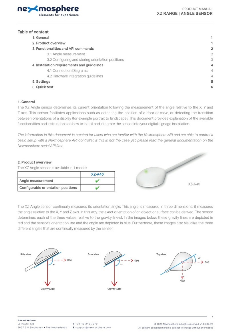
Nexmosphere
Nexmosphere XZ-A40 User manual
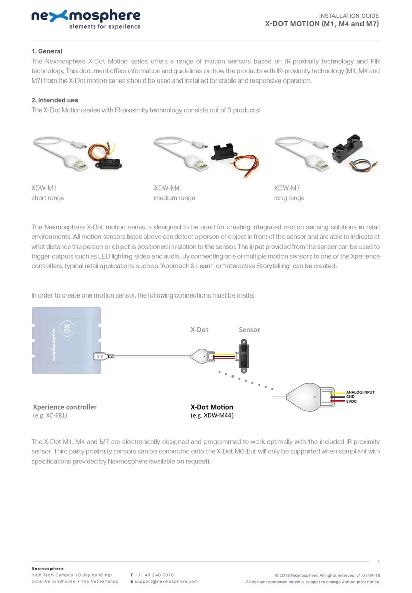
Nexmosphere
Nexmosphere X-Dot Motion Series User manual
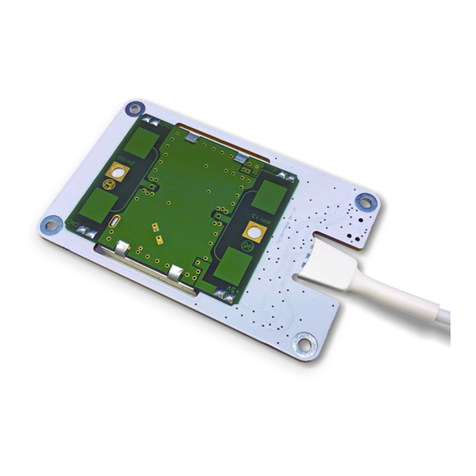
Nexmosphere
Nexmosphere X-EYE User manual

Nexmosphere
Nexmosphere XD Series User manual
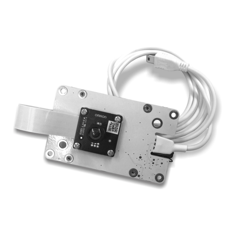
Nexmosphere
Nexmosphere X-EYE XY-510 User manual
Nexmosphere
Nexmosphere X-EYE 200 Series User manual
Nexmosphere
Nexmosphere X-EYE XY-116 User manual
Nexmosphere
Nexmosphere XF-P3W User manual
Nexmosphere
Nexmosphere XS Series User manual
