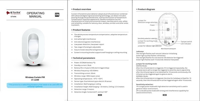
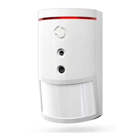
SILENTRON 5120 Small PIR-W User manual

Dichiarazione di conformità CE: l’apparecchiatura qui descria funziona
a 12V in corrente connua ed è componente accessorio di un sistema di
allarme eleronico che fa capo alle centrali Sil-Bus e/o Silenya HT, quindi
non ulizzabile svincolata da tale apparecchio, pur essendo conforme alle
seguen norme:
1) Direva CE 2004/108 del 15 dicembre 2004, relave alla compabilità
eleromagneca. Le Norme e/o speciche tecniche applicate sono le seguen: EN
50130-4 (1995-12) + A1 (1998-04) + A2 (2003-01) - EN 55024 (1998-09) +A1 (2001-
10) + A2 (2003-01) - EN 301489-1 V1.8.1 (2008-04) - EN 301489-3 V. 1.4.1 (2002-08)
- EN 301489-7 V1.3.1 (2005-11).
2) Direva CE 2006/95 del 12/12/2006: è applicata la Norma EN 60950-1 (2006-
049).
Avvertenze: l’apparecchiatura qui descria deve essere installata e messa in opera,
esclusivamente all’interno di locali, da tecnici specializza, nel rispeo delle Norme
vigen.
Funzionamento: questo apparecchio è espressamente studiato per segnalare
l’intrusione di persone all’interno dei locali. Ciò avviene rilevando dierenza di
temperatura fra il bersaglio in movimento entro l’area protea e lo sfondo: in
questo caso vi è allarme, visualizzato dall’accensione del led, ove non escluso in
fase di programmazione.
Autoprotezione: aprendo il vano dei collegamen elerici si ha allarme per
manomissione. Dovendo intervenire sui collegamen è necessario porre
prevenvamente la centrale in Test. L’apparecchio non dispone di anasportazione.
Istruzioni per l’installazione:
a) Installare SmallPir con vi e tasselli su un muro, tenendo conto dell’area
da proteggere. La posizione consigliata è in un angolo a circa 2,2m di altezza,
ulizzando il supporto in dotazione. Altezze di installazione inferiori riducono la
portata in distanza ma migliorano la copertura della zona soo il rivelatore. Ove
necessario è comunque disponibile uno snodo orientabile cod. 5961. Evitare
l’installazione vicino a possibili turbolenze di aria calda/fredda e dove animali a
sangue caldo accedono all’area protea: un accurato posizionamento e la riduzione
della sensibilità rendono possibile evitare che il movimento di piccoli animali
provochi allarmi non desidera.
b) Predisporre i dip-switch come necessario secondo l’impiego dell’apparecchio
(vedere gura)
c) Collegare la morseera dell’apparecchio con 3 li di diametro minimo 0,22 mm
all’alimentazione (+ e -) e l’uscita OUT ad un ingresso bilanciato della centrale. La
parte non isolata dei conduori deve essere interamente dentro i morse per
evitare cor circui.
d) Richiudere il rivelatore: ora sarà possibile dare alimentazione.
e) Eeuare prove funzionali e regolare opportunamente sensibilità e conteggio impulsi. Inserire la
compensazione di temperatura esclusivamente se l’apparecchio è installato in ambien costantemente molto
caldi.
Caraerische tecniche e regolazioni dell’apparecchio (vedere anche gure):
Classe ambientale 2 - interno
Alimentazione: 10,5-13,8V CC - assorbimento: 5mA
Visualizzazioni: led rosso acceso = allarme - escludibile ponendo il dip-switch 4 in ON
Area protea: circa 90° per circa 10m – portata regolabile araverso dip-switches 1 e 2
Conteggio impulsi 1 – 2, programmabili araverso dip-switch 3
Compensazione di temperatura - avabile araverso dip-switch 5
Compabilità uscita OUT : selezionabile per sistema Sil-Bus o Silenya HT araverso dip-switch 6
IT
Déclaraon de conformité CE: L’appareil qui est décrit fonconne à 12V en courant connu et est un
composant accessoire d’un système d’alarme électronique qui est géré par la centrale 4000 Sil-Bus,
donc inulisable séparée de cet appareil, tout en étant conforme aux normes suivantes :
1) Direcve CE 2004/108 du 15 décembre 2004, relaves à la compabilité électromagnéque. Les
Normes et/ou les spécicaons techniques appliquées sont les suivantes : EN 50130-4 (1995-12) + A1 (1998-
04) + A2 (2003-01) - EN 55024 (1998-09) +A1 (2001-10) + A2 (2003-01) - EN 301489-1 V1.8.1 (2008-04) - EN
301489-3 V. 1.4.1 (2002-08) - EN 301489-7 V1.3.1 (2005-11)
2) Direcve CE 2006/95 du 12/12/2006 : Norme appliquée EN 60950-1 (2006-049).
Averssements: l’appareil qui est décrit doit être installé et mis en service, uniquement à l’intérieur de locaux,
par des techniciens spécialisés et conformément aux normes en vigueur en la maère.
Fonconnement: cet appareil est spécialement étudié pour signaler l’intrusion de personnes à l’intérieur des
locaux. Cela se produit en détectant la diérence de température entre la cible en mouvement dans la zone
protégée par rapport au fond : dans ce cas, il y a une alarme visualisée par l’allumage de la led, là où elle n’est
pas exclue en phase de programmaon.
Autoprotecon : en ouvrant le comparment des branchements électriques on provoque le sabotage. S’il
faut intervenir sur les branchements, il faut d’abord placer la centrale en test. L’appareil ne possède pas de
protecon an-arrachement.
Instrucons pour l’installaon:
a) Installer SmallPir à l’aide des vis et des tampons sur un mur, en tenant compte de la zone à protéger. La
posion conseillée est dans un angle à environ 2,2 m de hauteur, en ulisant le support fourni en équipement.
Des hauteurs d’installaon inférieures diminuent la portée en distance, mais améliorent la couverture de la
zone sous le détecteur. Là où c’est nécessaire, on dispose d’une rotule orientable code 5961. Il faut éviter
l’installaon à proximité de possibles turbulences d’air chaud/froid et où des animaux à sang chaud accèdent
à la zone protégée : un posionnement minueux et la diminuon de la sensibilité permeent d’éviter que le
mouvement de pets animaux ne déclenche des alarmes non souhaitées.
b) Régler les pet interrupteurs comme il est nécessaire an de l’installaon
c) Connecter le bornier de l’appareil avec 3 ls de diamètre moindre 0,22mm à la centrale : deux à l’alimen-
taon (+ et -) et un de la sore OUT de l’appareil à une entrée IN de la centrale. La pare non isolée des
conducteurs doit être enèrement dans les bornes, pour éviter des courts-circuits.
d) Refermer le détecteur : maintenant il est possible de mere sous tension.
e) Eectuer des essais de fonconnement et régler l’appareil à l’aide du clavier de la centrale
Caractérisques techniques et réglages (voir également les gures):
Classe ambiante 2 - interne
Alimentaon : 10,5-13,8V CC
Consommaon : 5mA
Achages : voyant rouge allumée = alarme – Exclusion du voyant par pet interrupteur 4 (ON)
Zone protégée : environ 90° sur environ 10 m, réglable par pet interrupteurs 1 et 2
Comptage d’impulsion : 1 – 2 réglable par pet interrupteur 3
Compensaon de température : habilitaon par pet interrupteur 5
Compabilité de la sore OUT: à choisir pour système Sil-Bus ou Silenya HT à travers le pet interrupteur 6
FR
EC Declaraon of conformity: the described equipment funcons at 12V DC and is a component of
an electronic alarm system connected with the Sil-Bus or Silenya HT control panels. Therefore it can-
not be used if it is not connected to this appliance, although it complies with the standards below:
1) EC Direcve 2004/108 of 15th December 2004, relang to electromagnec compability. The
Standards and/or technical specicaons applied are: EN 50130-4 (1995-12) + A1 (1998-04) + A2 (2003-01)
- EN 55024 (1998-09) +A1 (2001-10) + A2 (2003-01) - EN 301489-1 V1.8.1 (2008-04) - EN 301489-3 V. 1.4.1
(2002-08) - EN 301489-7 V1.3.1 (2005-11).
2) EC Direcve 2006/95 del 12/12/2006: the EN 60950-1 (2006-049) Standard is applied.
Noce: the described equipment must be installed and started up by specialised technicians in accordance
with current Regulaons.
Funconing: this appliance is specially designed to signal the intrusion of a person within the premises. This
is done by detecng the temperature dierence between the target moving inside the protected area and the
background: In this case the alarm is triggered, the LEDs are turned on, unless excluded at the programming
stage.
Self-protecon: when the electric connecons compartment is opened, this triggers a tampering alarm.
When operaons have to be performed on the connecons, it is necessary to set the control panel to Test
beforehand. The appliance has no an-removal protecon.
Installaon instrucons:
a) Install SmallPir on the wall using screws and inserts, considering the area to protect. The recommended
posion is in a corner about 2.2m high, using the supplied support. If installed at a lower height this reduces
the distance range, but increases the detector’s coverage of the area. If necessary, there is a adjustable joint
code 5961. Avoid installaon near possible hot/cold air sources and where warm blood animals access the
protected area: accurate posioning and reduced sensivity make it possible to prevent triggering of unwan-
ted alarms depending by the movements of small animals.
b) Select the dip-switches as it is necessary for the right funconing of the system.
c) Connect the appliance’s terminal board to panel by 3 conductors with a minimum diameter of 0.22mm. : +
and – to the panel power supply and OUT to a input IN of the panel. The non-insulated part of the conductors
should completely be in the clamps to prevent short-circuits.
d) Close the detector: now it can be powered.
e) Perform funconal test and adjust the appliance using the dip-switches as showed.
Technical features and sengs (see also gures):
Environmental class 2 - internal
Power supply: 10.5-13.8V CC
Absorpon: 5mA
Visual Indicator: red LED on = alarm – can be cut o by dip-switch 4 ON
Protected area: about 90° by approx. 10m – range adjustable by dip-switches 1-2
Pulse counng: 1 – 2 programmable by dip-switch 3
Temperature compensaon: it can be switched on by dip-switch 5
Compabilty OUTput: selected for Sil-Bus or Silenya HT System by dip-switch 6
EN
EG-Konformitätserklärung : das hier beschriebene Gerät funkoniert mit 12V Gleichstrom und ist,
als Zubehör Bestandteil eines elektronischen Alarmsystems, das zur Zentralen Sil-Bus und /oder Si-
lenya HTgehört und daher nicht unabhängig von diesen Geräte eingesetzt werden kann, auch wenn
es mit folgenden Richtlinien übereinsmmt:
1) Richtlinie EG 2004/108 vom 15. Dezember 2004 bezüglich der elektromagneschen Verträglichkeit. Die
Richtlinien und/oder angewandten technischen Spezikaonen sind folgende: EN 50130-4 (1995-12) + A1
(1998-04) + A2 (2003-01) - EN 55024 (1998-09) +A1 (2001-10) + A2 (2003-01) - EN 301489-1 V1.8.1 (2008-04)
- EN 301489-3 V. 1.4.1 (2002-08) - EN 301489-7 V1.3.1 (2005-11)
2) Richtlinie EG 2006/95 vom 12.12.2006: wurde die Richtlinie EN 60950-1 (2006-049) angewandt.
Hinweise: das hier beschriebene Gerät muss unter Wahrung der geltenden Richtlinien vom Fachpersonal
ausnahmslos im Innern von Räumen installiert und in Betrieb genommen werden.
Funkonsweise: dieses Gerät wurde eigens dazu entwickelt, um ein Eindringen von Personen in Räumlichkeit-
en anzuzeigen. Dies erfolgt über die Erfassung der Temperaturdierenz zwischen einem Objekt in Bewegung
und dem Hintergrund. Das Auslösen des Alarms wird durch Aueuchten der LED angezeigt, sofern dies nicht
in der Programmierphase ausgeschlossen wurde.
Selbstschutz: Das Önen des Gehäuses löst Sabotagealarm aus. Falls ein Eingri notwendig ist, muss die Zen-
trale vorher in den Testmodus versetzt werden. Das Gerät verfügt über keinen Abreißschutz.
Installaonsanweisungen:
a) Small-PIR mit Schrauben und Dübeln an die Wand moneren mit Rücksicht auf den zu überwachenden
Bereich. Die opmale Posionierung ist in einer Ecke in etwa 2,2m Höhe unter Benutzung der beiliegenden
DE

Halterung. Eine Montage, die unter der angegebenen Höhe ist, reduziert die Reichweite, verbessert aber die
Abdeckungseigenscha der Überwachungszone unter dem Melder. Wo dies benögt wird steht auf alle Fälle
ein Gelenk zum Ausrichten des Melders zur Verfügung (Art.-Nr. 5961). Vermeiden Sie Installaonen in der
Nähe von möglichen Warm-/Kaltluwirbeln und dort, wo warmblüge Tiere in den Überwachungsbereich
Zugang haben. Eine sorgsames posionieren sowie die Verringerung der Sensorempndlichkeit ermöglicht es,
verhindert das Auslösen unerwünschter Alarme (z.B. durch kleiner Tiere).
b) Dip-Switch wie benögt nach der Gerätsanwendung einrichten (nach Darstellung)
c) Die Klemmleiste des Geräts mit 3 Drähten mit Minimum Durchmesser 0,22mm zum Stromversorgung (+
und -) und der Ausgang AUS zu einem ausglichen Zentraleseingang anschließen. Der nicht isolierte Teil der
Leiter muss sich vollständig in den Klemmen benden, um Kurzschlüsse zu vermeiden.
d) Den Melder wieder schließen: nun kann die Stromversorgung wieder hergestellt werden.
e) Durchführen von Betriebstests und sowohl die Empndlichkeit des Geräts als auch die Zählen der Impulse
einstellen. Einschalten die Temperaturasugleich nur im Fall das Gerät in ständig sehr wärmen Zone eingestellt
wurde
Technische Daten und Einstellungen des Geräts (siehe auch die Zeichnungen):
Umweltklasse 2 - innen
Versorgung: 10,5-13,8V CC-
Aufnahmeleistung: 5mA
Anzeige: rote LED ein = Alarm-abschaltbar beim Dip-Switch 4 in EIN Schalten
Überwachungsbereich: von etwa 90°bis etwa 10m –einstellbare Reichweite miels dip-switches 1 und 2
Zählen der Impulse 1 - 2;programmierbar miels dip-switch 3
Temperaturausgleich- schaltbar miels dip-switch 5
Austauschbarkeit Ausgang AUS: auswählbar miels dip-switch 6 sowohl für Sil-Bus als auch Silenya HAT Sy-
stem
Other SILENTRON Security Sensor manuals
SILENTRON
SILENTRON StarPir HT User manual

SILENTRON
SILENTRON 7175 User manual
SILENTRON
SILENTRON 5414 User manual
SILENTRON
SILENTRON 5011 User manual
SILENTRON
SILENTRON 5013 User manual
SILENTRON
SILENTRON DualTech HT User manual
SILENTRON
SILENTRON 5514 SILENT Dual Tech User manual

SILENTRON
SILENTRON 5513 LaserBeam HT User manual

SILENTRON
SILENTRON PhotoPir 5525 User manual
SILENTRON
SILENTRON 714 Series User manual

