Sipromac 350 User manual

1
VACUUM PACKAGING MACHINE
MODELS 350 & 350D
OWNERS MANUAL
(MANUEL D’UTILISATION)
(MANUAL DE UTILIZACIÓN)

2

3
IMPORTANT SAFETY INSTRUCTIONS
SAVE THESE INSTRUCTIONS
This symbol points out important safety instructions which, if not followed,
could endanger the personal safety and/or property of yourself and
others. Read and follow all instructions in this manual before attempting
to operate your machine.
Failure to comply with these instructions may result in personal injury.
General Operation
Read, understand, and follow all instructions in the manual and on the machine
before starting. Keep this manual in a safe place for further and regular reference and
for ordering replacement parts.
Only allow responsible individuals familiar with the instructions to operate the
machine. Be sure to know controls and how to stop the machine quickly.
Never put your hands near moving parts.
Only allow qualified individuals for the maintenance of your machine.
Remove all obstacles, which may interfere with the machine functions.
Clear the work area such as electrical wires, buckets, knives etc.
Be sure that everyone else is clear of your work area before operating the machine.
Do not sit nor stand on the machine.
Always turn off the machine after your work is done. Never leave a running machine
unattended.
Always disconnect and wait till the machine has cooled before attempting any
maintenance.
Do not wear loose fitting clothes or jewelry as they may get caught in moving parts of
the machine.
Always wear security shoes, to prevent injury caused by moving the machine or
objects falling from the machine.
Never exceed the time limit to seal, which is recommended by the manufacturer. This
is to avoid any damage that may be caused to the sealing bars and to eliminate the
risk of fire in the machine. Thus avoiding corporal burns.
Never touch the sealing bars after they have been used, this will avoid corporal burns.
Wait a few minutes to let the machine cool down before touching.
Always make sure that the sealing bars are well installed in their "Guide Blocks" before
starting a cycle.

4
Never incline the machine more than 30 degrees, it may tip over and hurt someone
seriously.
Work only in daylight or good artificial light.
Do not operate any appliance with a damaged cord or plug, or after the appliance
malfunctions or is dropped or damaged in any manner. Return appliance to the
nearest authorized service facility for examination, repair, or electrical or mechanical
adjustment.
Do not operate the machine while under the influence of alcohol or drugs!
Service
Use proper containers when draining the oil. Do not use food or beverage containers
that may mislead someone into drinking from them. Properly dispose of the
containers, or store in a safe place immediately following the draining of the oil.
Prior to disposal, determine the proper method to dispose of waste from your local
office of Environmental Protection Agency. Recycling centers are established to
properly dispose of materials in an environmentally safe fashion.
Do not pour oil or other fluids into the ground, down a drain or into a
body of water.
Warning-Your responsibility:
This machine should only be operated by personal who can read, understand and
respect warnings and instructions regarding this machine in the owner’s manual.
Save these instructions for future reference.
INSTALLATION NOTICE FOR MODELS:
350, 350D
IN ORDER TO RESPECT NSF REGULATIONS:
The table, on which the machine has to be installed, should be of open frame type, to
avoid dirt accumulation, and to allow easy cleaning under the machine.

5
Contents
1. SETTING UP THE MACHINE ............................................................................................................... 6
2. ELECTRICAL CONNECTION............................................................................................................... 6
3. OPERATION.......................................................................................................................................... 7
A.WORKING PRINCIPLES ..............................................................................................................................7
B.GAS FLUSHING (OPTION)........................................................................................................................... 8
C.ELECTRICAL BAG CUT (OPTION).................................................................................................................8
D.PRESSURE REGULATOR (OPTION).............................................................................................................. 8
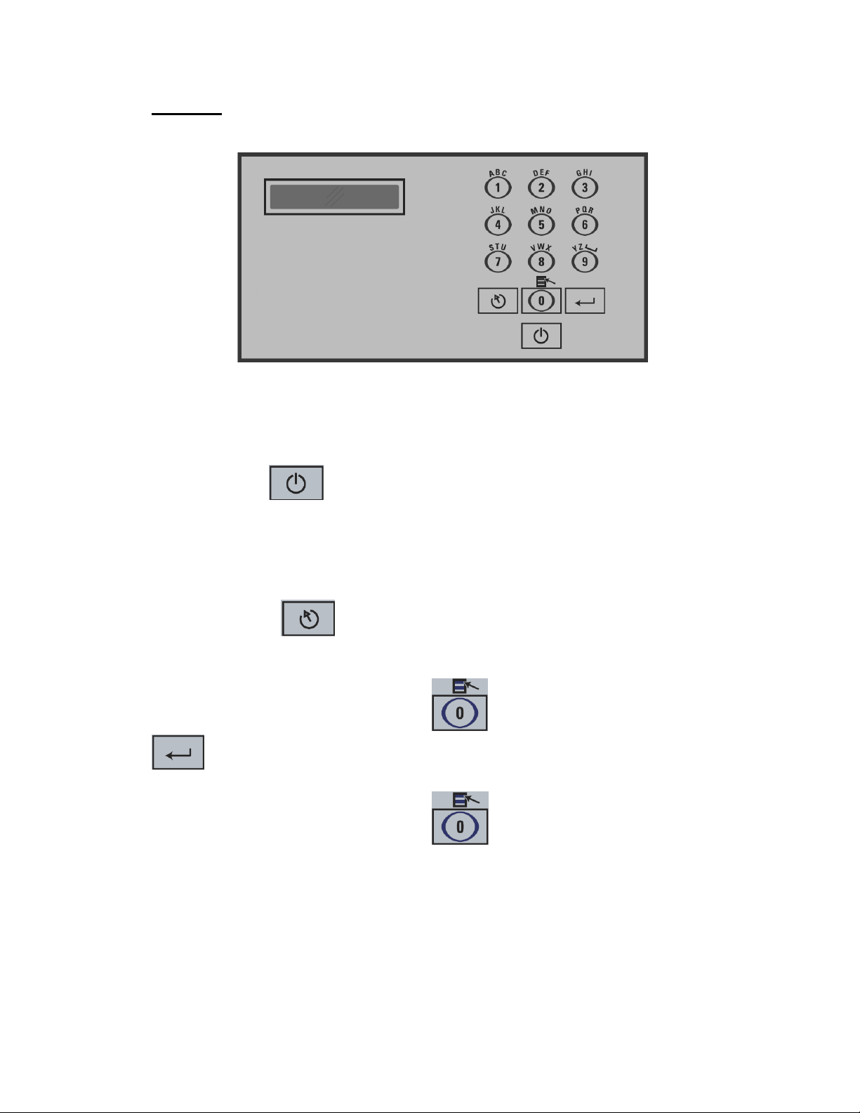
4. CONTROL ............................................................................................................................................. 9
A.BASIC...................................................................................................................................................... 9
B.VACUUM LEVEL SETTING.........................................................................................................................10
C.VACUUM PLUS SETTING .......................................................................................................................... 11
D.GAS FLUSH LEVEL SETTING.....................................................................................................................11
E.SEALING TIME SETTING...........................................................................................................................12
F.PACKAGING CYCLE.................................................................................................................................12
G.SYSTEM MONITOR AND DIAGNOSTIC MENU...............................................................................................12
H.MENUS STRUCTURE ...............................................................................................................................13
5. DAILY CLEANING ..............................................................................................................................14
6. TROUBLESHOOTING ........................................................................................................................ 15
A.FAILURE DURING PACKAGING CYCLE........................................................................................................ 15
B.INSUFFICIENT VACUUM............................................................................................................................15
C.FAULTY SEAL .........................................................................................................................................15
D.FAULTY VALVE .......................................................................................................................................16
E.CONTROL BOARD FAILURE ......................................................................................................................16
7. MAINTENANCE ..................................................................................................................................16

6
1. Setting up the machine
Before choosing the site for the machine, please consider that you will also need
room for packaged and non-packaged products apart from the space needed for
the machine itself.
Before starting to work, check the oil view glass on the pump, if there is a sufficient
quantity of oil in the pump. Never use oil other than recommended by the producer.
Never exceed maximum quantity of oil indicated, when adding or changing oil.
Verify weekly.
Normal operating temperature for the 350/350D is 4C to 32C (39F to 90F).
Vacuum pump is filled with synthetic oil that can be used in that range of
temperature.
2. Electrical connection
Electrical connections must be made by qualified personnel. This person must
make sure that the electrical entries correspond to the proper voltage and
amperage of the machine. GROUNDING INSTRUCTIONS: This appliance must be
grounded. In the event of malfunction or breakdown, grounding provides a path of
least resistance for electric current to reduce the risk of electric shock. This
appliance is equipped with a cord having an equipment-grounding conductor and a
grounding plug. The plug must be plugged into an appropriate outlet that is
properly installed and grounded in accordance with all local codes and ordinances.
DANGER Improper connection of the equipment-grounding conductor can result in
a risk of electric shock. The conductor with insulation having an outer surface that
is green with or without yellow stripes is the equipment-grounding conductor. If
repair or replacement of the cord or plug is necessary, do not connect the
equipment-grounding conductor to a live terminal. Check with a qualified electrician
or serviceman if the grounding instructions are not completely understood, or if in
doubt as to whether the appliance is properly grounded. Do not modify the plug
provided with the appliance if it will not fit the outlet; have a proper outlet installed
by a qualified electrician.

7
3. Operation
a. Working principles
A vacuum packaging cycle is made of 3 stages. First the vacuum is made, the air
is completely taken out of the chamber and from bag containing the product (see
figure 1). Then it is possible to inject neutral gas from the nozzles, gas flushing
extended product shelf life and also act as a cushion for delicate product. Finally, a
mechanism pushes the sealing bar to the rubber support to seal the bag.
To obtain nice packages, the products and the bags have to be of proportional
sizes. The bag's opening should never exceed 5 cm (2") past the seal bars. The
product should be centered in height in relation to the seal bar by adjusting the
spacers provided (see figure 1).
To obtain a good seal, make sure that no residue of fat is left between the bag's
inner sides where sealing is done.

8
b. Gas flushing (option)
There is an atmospheric pressure of 1 kg/cm2 (14 PSI) upon products when fully
evacuated. Products which can be damaged by high pressure must be packaged
with a partial vacuum, or the pressure must be counterbalance by inflating the bag
with neutral gas.
For gas flushing, the bags are placed on the sealing bars, the open ends placed
over the gas nozzles mounted alongside the sealing bar. After evacuation, the
vacuum valve closes and the gas valve opens. Gas quantity (%) can be set in the
program.
The necessary gas tank and pressure regulator mounted on tank is not supplied,
The pressure of the gas regulator should be set at approximately 1/3 kg/cm2 ( 5
PSI ). Each machine has an adaptor for gas connection when gas flush option is
ordered.
c. Electrical bag cut (option)
This option is used to obtain a package that the excess bagtail is cut off close to
the seal.
d. Pressure regulator (option)
This option is used to obtain more sealing pressure between the sealing bar jaw.
Suggested option for low vacuum level packaging or high level gas flushing. Also
recommended for hard to seal laminated bags. Each machine has an adaptor for
compressed air connection when pressure regulator option is ordered.
Recommend pressure regulator adjustment is 1 kg/cm2 (14 PSI), maximum setting
1.3 kg/cm2 (20 PSI),

9
4. Control
a. Basic
Use power key to power the vacuum packaging machine. When the unit is
energized, the identification of the last executed program is displayed on LCD
screen. To disconnect, use the power key to turn off the machine, then remove
plug from outlet. Do not unplug by pulling on cord. To unplug, grasp the plug, not
the cord. Unplug from outlet when not in use and before servicing or cleaning.
Use the esc key to change over from the programs menu to the functions
menu and from the functions menu to the programs menu.
In functions menu, use select key to select a function and enter key
to accede and executed the selection.
In programs menu, use select key to select a program and enter key
to accede and modify the selection.
In programs submenu, use enter key to pass over the parameters and point to the
following one; the parameters are blinking to point out the acquisition mode. A
return to programs menu is performed automatically following the last parameter
acquisition.

10
In program submenu, use esc key to get back to the programs menu.
Strike any key to clear the error messages which may be displayed on LCD
screen. Menu Structure can be found in section 4.H.
Create a program:
When executing the "create a program" function, the program submenu is
acceded, starting with the identification. The initial identification "Pxx NO NAME" is
given to the program and all parameters are established to zero; the program
number is allocated automatically.
Delete a program:
When executing the "delete a program" function, the programs menu is acceded
and the number of the first program in memory is blinking to point out the deletion
mode. Use select key to select a program and enter key to accede
and confirm deletion of the selection. Use esc key to unconfirm a deletion
and to leave the function. When leaving the function, the number of the actual
program on LCD screen cease to blink.
Program identification:
For a selected program, set the identification, using the numeric keyboard
characters chart; press numeric key until the desired character is selected (4 times
for the numeric value). Use enter key to validate the character and to
validate the characters string at the end (the new characters string is blinking). In a
middle of an acquisition, use esc key to come backward and erase one or
several characters.
For example, to use a ‘E’ caracters, press number 2 two times and une the enter
key to confirm.
b. Vacuum level setting
For a selected program set the vacuum level, starting with the values; the decimal
point is automatically inserted following the second digit entry and the validation is

11
automatically performed following the third digit entry (the new vacuum level is
blinking). In the middle of an acquisition, use enter key to validate the
vacuum level and key "ESC" to come backward and start over with a new
acquisition. Set vacuum level to zero to bypass the pressure transducer and
proceed only using the vacuum plus time.
A vacuum set point over 99.5% is not recommended. Hot products or very humid
product may require a lower set point.
c. Vacuum plus setting
For a selected program set the vacuum plus time, in seconds; the validation is
automatically performed following the second digit entry (the new vacuum plus
time is blinking). In a middle of an acquisition, use enter key to validate the
vacuum plus time and use esc key to come backward and start over with a
new acquisition.
d. Gas flush level setting
For a selected program set the gas flush level following the same procedure as for
the vacuum level; the maximum gas flush level setting is 10% below the vacuum
setting. Maximum recommended gas flushing level is 80%, compressed air
regulator option is recommended at this gas flushing level.

12
e. Sealing time setting
For a selected program set the sealing, starting with the seconds; the decimal point
is automatically inserted following the first digit entry and the validation is
automatically performed following the third digit entry (the new sealing time is
blinking. In a middle of an acquisition, use enter key to validate the sealing
time and use esc key to come backward and start over with a new
acquisition (the old sealing time is blinking).
f. Packaging cycle
Chose a program (see basic section) and place the bags on the sealing bar, close
the cover to initiate a vacuum cycle. During cycle execution the operation status is
sequentially displayed on LCD screen, except for the parameters established to
zero, which are not displayed:
Vacuum status % during vacuum sequence
Vacuum plus time (seconds)
Gas status % during gas flush sequence
Sealing time status during sealing sequence (seconds)
ATM message during venting sequence
During cycle execution, use key "1" to abort the vacuum sequence and execute the
following sequence, which is gas flush or sealing, use enter key to accede
and modify the program; the parameters become valid only for the following
vacuum cycles.
g. System monitor and diagnostic menu
To access the diagnostics menu, power up the vacuum packaging machine
while keeping pushed in esc key . Use select key to select
the system monitor function and enter key to access and visualize the
monitored parameters. A password is required for some menus, contact your
service center for support. Use select key to change over from the
software revision, the amount of working hours done and the amount of complete
cycles performed since first initialization. See menus structure next.

13
h. Menus structure
•Functions menu:
"F1 CREATE A PRGM"
"F2 DELETE A PRGM"
•Programs menu:
"Pxx NAME"
Program submenu:
"VACUUM: xx.x%" (10.0% - 99.5%)
"VACUUM PLUS: xxs" (0s - 99s)
"GAS FLUSH: xx.x%" (0.0% - 10% below the vacuum level) (units with gas
option)
"SEAL TIME: x.xxs" (0.00s - maximum unit allocated setting)
"Pxx NAME" (12 characters)
•Diagnostics menu (keys "ESC" & "POWER" for access):
"DIAGNOSTICS MENU" (access code required)
"D1 INPUTS TEST" Show the input status
"D2 OUTPUTS TEST" Test the output of the card
"D3 MODEL SELECT" Select the model of the machine
"D4 GAS OPTION" Enable or disable the gaz option
"D5 SEALING TIME" Set the maximum sealing time
"D6 COOLING TIME" Set the cooling time
"D7 OFFSET CALIB” Show the current vacuum calibration
"D8 VACUUM SENSOR” Enable or disable vacuum sensor

14
“D9 ACCESS CODE” Enable or disable the access code to modify the programs
“D10 CODE CHANGE” Modify the program access code
"D11 PUB” Enable or disable the screen saver message
“D12 SELECT PUB” Factory use
“D13 VACUUM CALIB” Automated calibration sequence
"SYSTEM MONITOR" (no access code required)
"SOFTWARE: R x.xx" Show the software version
"WORK HRS: xxxxx" Show the number of operating hours
"CYCLES: xxxxxxx" Show the total number of cycles
S: XXX.X T: XXX.X Show the set point and the current temperature for the heating
option
5. Daily cleaning
For hygienic cleanliness, it is imperative to clean chamber and spacers daily. Also
clean the lid rubber to assure tight seat of the lid. The 350/350D is made to be
clean by hand with a damp cloth, no water can be apply directly on the machine.
Cleaning instructions for gas injection nozzles (option): Periodically, on a
regular basis, the gas injection nozzles must be removed with the connection tube
and soaked in a food grade soap and water solution, then dried and re-installed.

15
6. Troubleshooting
a. Failure during packaging cycle
COVER DOWN ERROR’’ message is display on LCD. The input signal of the
down position switch has been lost during cycle execution. Check limit switch
adjustment.
b. Insufficient vacuum
Most frequently, insufficient vacuum in bags is due to leakage in bag and not due
to any fault of the machine. Pin-hole leak for which there is no obvious explanation
is due to faulty bag material. Use bone-guard or thicker film for pin-hole leak
caused by sharp edge of the product (bone, etc.). Tear in bag by careless
handling can also be the source of the problem (sharp edge on filling table,
damage made by retailer or customer).
If no leak in the bag can be found, make sure you use a bag of the appropriate
size. Vacuum setting may also be too low. Check vacuum sensor with a remote
vacuum sensor. Sealing bar can also be jammed or sealing valve is not working
properly, see with service center. Vacuum pump may also need a check-up.
c. Faulty seal
Insufficient seal problem can be related to damaged Teflon or silicone rubber. Can
also be from a low sealing pressure, a leaking bellow or the sealing bar are
jammed. If there is no seal at all, the sealing wire may be or one of the electrical
component is not working properly (wire, sealing transformer, contactor. If the
sealing bar have a permanent current, check the contactor. In a case of non-
sticking seal, check bag quality (insufficient layer of poly PE). Seal area have to be
clean of contamination like juice and fat. In that case, use filling accessory.
Warning: Do not increase sealing time more than really necessary; higher
temperature will reduce working life of teflon and silicone rubber.
WARNING: All electrical work described in this brochure
should be done by a QUALIFIED and AUTHORIZED technician.

16
d. Faulty valve
Check whether there is voltage on the magnetic valves during their period of
operation. If there is no voltage a wire is broken or the PC board is damaged.
If the lid does not open at the end of the cycle; air enters, but there is still 20 - 40%
vacuum in chamber, vacuum valve does not close (needs to be serviced).
e. Control board failure
This board software is allowing access to a "Diagnostics Menu". Only qualified
service technicians are authorized to access this menu by entering a security
password.
By acceding either the "D1 input test" feature or the "D2 output test" feature, a
trained technician will be able to quickly know the origin of the problem: pump,
sealing system, pneumatic problem, security switches problem, etc...
Keep in mind that in most cases trouble is due to a leakage, loose electrical
Keynesian or evident damage to the main component: vacuum pump, valves...,
electrical contactors, thermal overload, fuses holder or transformer.
For assistance do not hesitate to contact your local service technicians.
7. Maintenance
Routine controls must be made a qualified technician, contact your local service
center.
Routine controls list:
Check teflon for wear.
Check silicone rubber for burnt spots and smooth even position.
Check pressure bar for jamming.
Check lid sealing for damage and hardened spots.
Check switch-point of micro switch, adjust if necessary.
Check evacuation hose for damage (contraction of diameter, or abrasions).

17
Check vacuum connections for tightness.
Check oil in pump (oil level in view glass; add if necessary. Regular change of oil -
necessity indicated by change of color). Follow Busch maintenance schedule.
Check vacuum in chamber with precision vacuumeter.
Check desiccant filter for proper color, change if necessary.
Check function of cycle with various settings of timers.This board software is
allowing access to a "Diagnostics Menu". Only qualified service technicians are
authorized to access this menu by entering a security password.

MACHINE
PART
ITEM
MAT.
CNC
DWG BY
APP. BY
DATE
DATE
QTY.
DEPT.
SIPROMAC
ST-GERMAIN DE GRANTHAM
QUEBEC CANADA
DEPT. TOL.
USINAGE
TOLERIE
SOUDAGE
METRIC
± 0.1
±
0.5
±
0.
5
INCH
± 0.004"
±
0.020"
±
0.020"
N.T.S.
NO.
004A4142
S.L. 1
M
350
MACHINE ASSEMBLY
13-11-22 004A4142
LET. MODIFICATION
DATE
INT.
ABERKEL OPTION ADDED
15-02-24
SBU
1
12
7
1120
ITEM PART # DESCRIPTION QT.
1 004B0229 VACUUM PRE-ASSEMBLY 1
2 005B0266 COVER ASSEMBLY 1
3 004A1224 SPRING PRE-ASSEMBLY 2
4 005E0832 MC-40 FRONT PANEL ASSEMBLY 1
5 004A4144 VALVE ASSEMBLY VACCUM SENSOR 1
6 004A4133 VALVE ASSEMBLY PUMP 1
7 004C3857 REAR PANNEL PRE-ASS'Y 1
8 051-0740 WASHER 1/4" FLAT S/S 8
9 051-0581 NUT 1/4"-20 NYLON LOCK S/S 4
10 051-0930 BOLT M6 x 10 S/S 4
11 004A4112 NSF FOOT 4
12 004A3374 LIMIT SWITCH ASS'Y 1
13 004-0042 ELEC. SUPPORT PRE-ASS'Y 1
14 036-0400 WIRE CONNECT. 3/8'' NPT
CD09/O-RING/NUT 2
15 036-0200 GROMMET 5/8"IDx1 1/8"OD RUBBER 1
16 036-0390 CABLE CONNECT.3/8"-1/2"METAL 1
17 005-0532 BELLOWS ASSEMBLY 1
18 002-0029 LEFT SEAL BAR GUIDE BLOCK 1
19 002-0030 RIGHT SEAL BAR GUIDE BLOCK 1
20 005A0278 FILLER PLATE ASS'Y 1
21 005A0364 HALF FILLER PLATE ASS'Y 2
22 005A1584 MC-40 FRONT PANEL ASSEMBLY (BERKEL) 1
6
2
3
14
1998
17
108
4
5
13
21
22 BERKEL

MACHINE
PART
ITEM
MAT.
CNC
DWG BY
APP. BY
DATE
DATE
QTY.
DEPT.
SIPROMAC
ST-GERMAIN DE GRANTHAM
QUEBEC CANADA
DEPT. TOL.
USINAGE
TOLERIE
SOUDAGE
METRIC
± 0.1
±
0.5
±
0.
5
INCH
± 0.004"
±
0.020"
±
0.020"
N.T.S.
NO.
004A4136
S.L. 1
M
350D
MACHINE ASSEMBLY
13-11-22 004A4136
LET. MODIFICATION
DATE
INT.
ABERKEL OPTION ADDED
15-02-23
SBU
18
19
13
1
3
12
7
11
6
5
20
2
17
4
9
8 10
ITEM PART # DESCRIPTION QT.
1 004B0230 VACUUM PRE-ASSEMBLY 1
2 005B0481 COVER ASSEMBLY 1
3 004A1224 SPRING PRE-ASSEMBLY 2
4 005E0832 MC-40 FRONT PANEL ASSEMBLY 1
5 004B4134 VALVE ASSEMBLY VACCUM SENSOR 1
6 004A4133 VALVE ASSEMBLY PUMP 1
7 004C3857 REAR PANNEL PRE-ASS'Y 1
8 051-0740 WASHER 1/4" FLAT S/S 12
9 051-0581 NUT 1/4"-20 NYLON LOCK S/S 8
10 051-0930 BOLT M6 x 10 S/S 4
11 004A4112 NSF FOOT 4
12 004A3374 LIMIT SWITCH ASS'Y 1
13 004-0042 ELEC. SUPPORT PRE-ASS'Y 1
14 036-0400 WIRE CONNECT. 3/8'' NPT
CD09/O-RING/NUT 4
15 036-0200 GROMMET 5/8"IDx1 1/8"OD RUBBER 1
16 036-0390 CABLE CONNECT.3/8"-1/2"METAL 1
17 005-0532 BELLOWS ASSEMBLY 1
18 002-0029 LEFT SEAL BAR GUIDE BLOCK 2
19 002-0030 RIGHT SEAL BAR GUIDE BLOCK 2
20 005A0365 FILLER PLATE ASS'Y 2
21 036-0400 WIRE CONNECTOR 3/8'' NPT NUT 2
22 005A1584 MC-40 FRONT PANEL ASSEMBLY (BERKEL) 1
23 001A0564 VALVE SUPPORT 1
24 051-0143 SCREW 10-24 x 3/8" PAN PHIL S/S 2
25 051-0571 NUT #10-24 S/S 2
22 BERKEL
14

MACHINE
PART
ITEM
MAT.
CNC
DWG BY
APP. BY
DATE
DATE
QTY.
DEPT.
SIPROMAC
ST-GERMAIN DE GRANTHAM
QUEBEC CANADA
DEPT. TOL.
USINAGE
TOLERIE
SOUDAGE
METRIC
± 0.1
±
0.5
±
0.
5
INCH
± 0.004"
±
0.020"
±
0.020"
N.T.S.
NO.
005C0610
S.L. 1
M-I
350
MACHINE ASSEMBLY WITH OPTION
13-11-22
005C0610
LET. MODIFICATION
DATE
INT.
ITEM PART # DESCRIPTION QT.
1 004A4142 MACHINE ASSEMBLY 1
2 005B1031 STAND ASSEMBLY 19" (OPTION) 1
3 125-1021 BUSCH KB-0020 220-240V/1PH/50-60HZ 1
4 114-2009 SILENCER 1/2 NPT TOPRING 1
5 005A1424 GAS OPTION 1
6 005A1420 SOFT AIR OPTION 1
7 005A1421 AIR OPTION 1
8 005A1355 SEAL BAR ASSEMBLY W/SUPP. TWIN SEAL 1
9 005A1356 SEAL BAR ASSEMBLY W/SUPP. BAG CUT 1
10 125-1020 BUSCH KB-0020 115V/1PH/60HZ 1
1
2
A
DETAIL A
4
6
5
7
3 10
INSTALLER SUR LA VALVE LORS
DE L'OPTION SOFT AIR
This manual suits for next models
1
Table of contents
Other Sipromac Packaging Equipment manuals
Popular Packaging Equipment manuals by other brands

quadient
quadient AS-650 quick start guide

Minipack-Torre
Minipack-Torre Galileo Installation, operation and maintenance

ITATOOLS
ITATOOLS ITA21 Operation manual and parts list

CAMPAGNOLO
CAMPAGNOLO C 95 1-2 Use and maintenance manual

Minipack-Torre
Minipack-Torre eco modular instruction manual

ITW Mima
ITW Mima G2506 Service and installation manual

Pro Mach
Pro Mach Wexxar BEL Series Operation & service manual

Dynaric
Dynaric MUL-320 Operation manual

Greenbridge
Greenbridge B600 Operation manual

Advanced Poly-Packaging
Advanced Poly-Packaging Advanced Poly-Bagger T-1000 Operation guide

morse
morse 185A/E quick start guide

strapex
strapex SMA 20 operating instructions